


I wanted to start a new thread to show the progress of the Initial Run of Platform CNC Kits! I became extremely busy over the last two months working full time and producing these kits and had no time to post any updates here although I tried to email weekly updates to the people involved in the Initial Run. I wanted to save these updates and make a comprehensive post about the progress we made! I can't say thank you enough to people who decided to take the plunge and to make this all possible! Also a huge thank you to Ahren from CNCRouterparts.com, for bundling the components and even helping to source other parts to make the Initial Run of Platform CNCs go so smoothly!
Onto the Update! (this is going to be a long one)
Around November 20th, I began accepting deposits on kits just to be sure there was enough interest to move forward and to do a run. I needed at least 5 people to come on board in order to make it worth doing based on the drop off in savings by doing multiples.
On December 2nd, I received the 5th order, excited to be able to move forward, I went to bed thinking that I would update the website the following day to reflect the news. The following morning, I had received 3 more deposits and emails from two people on the fence. This meant that we had 10 people more or less committed, so I closed the run and placed the order for 12 machines worth of steel and aluminum. At this point, I wanted to order one machine for myself so that I could have a Production machine with all of the components that had changed from the Prototype and also to have one spare parts machine just in case there was any issues with QC.
At this point, we were ahead of schedule but I also knew that we needed to get our parts into production before the Holiday break or we would lose 2 solid weeks. I could also use the time over the break to prep and paint the steel and to work on finishing the aluminum pieces. With the steel order placed on December 6th and the aluminum ordered on December 12th, we were in very good shape to meet this goal. The steel quote estimated 5-7 days and the aluminum was estimated at 2-3 days. From experience, I know that you can generally double this for a conservative estimate of the actual time things take but this still looked like we would receive the parts before the holidays!
On the 12th of December, I called the steel fabricators to check on the progress. They explained that one of their lasers was down and were trying to get it back up and running. They were far behind at this point and the parts would be delayed. This is the first time I have ever experienced a delay with this company, but things were still looking good for a pre holiday delivery. I called the aluminum company a couple days later and found out that they still needed to order the material and would start cutting as soon as it arrived.
Based on these delays, I decided to begin working on the assembly document. I had planned to do this after all of the kits had been delivered so that I could focus on the document and do some assembly videos. Around this time, a gentleman I met at Makerfaire and had promised a kit resurfaced and I agreed to sell him spot number 11. Two days later, another local person contacted me about coming to see the Prototype. After a couple hours of talking and playing around with my machine, I reluctantly agreed to sell him spot number 12, this meant that I would no longer have a machine of my own from this batch. Oh well, I guess this means I have to do another run!
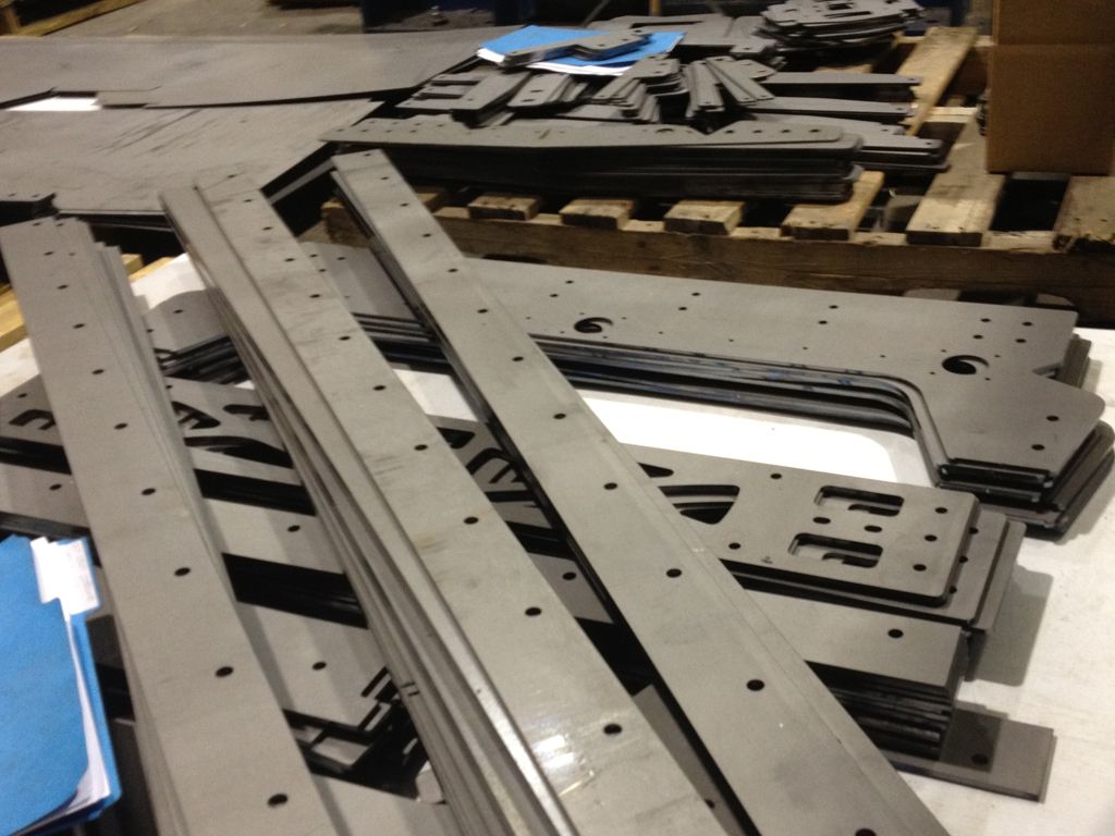
I stopped by the steel fabrication shop to check on another job on Jan 2nd. At this point, their machine was back up and running and they had cut all of the steel but still needed to form the pieces. They were extremely backed up at this point and it would be another two weeks before our parts were delivered.
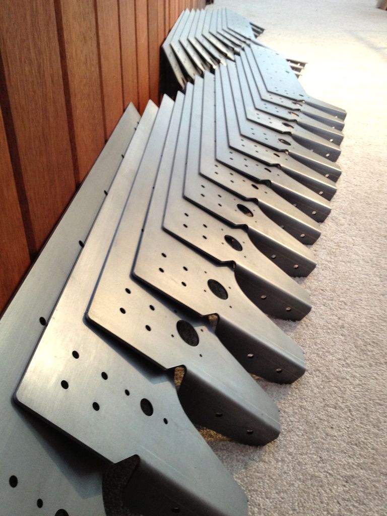
Here you can see all of the flat steel waiting to be formed...
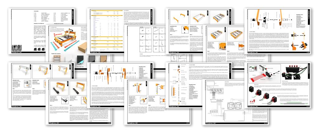
I went back to work on the assembly document to use the downtime to get the ahead of the curve and use the extra time over the holidays to put together a comprehensive document including over 100 high quality renderings with wiring diagrams and step by step assembly instructions. This is still a work in progress at this point, and I will continue to add more information to it as things develop.
The steel was finally delivered on the 16th of January, and I was able to pick up the aluminum 2 days later. I now had almost a ton of steel and aluminum in my living room, shop and studio that needed to be prepped for paint, and powder coating.
Steel in the Shop...
Steel in the Studio...
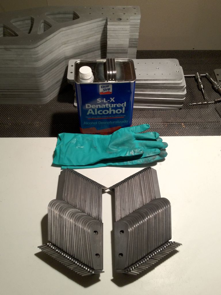
I really only needed to prep those parts I was going to paint black, but I went ahead and cleaned all of the steel with abrasive pads and denatured alcohol. The powder coater assured me they were going to do all of the necessary prep work, media blast and iron phosphate the parts that would be powder coated.
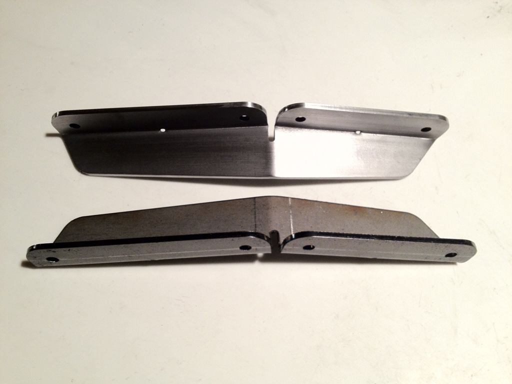
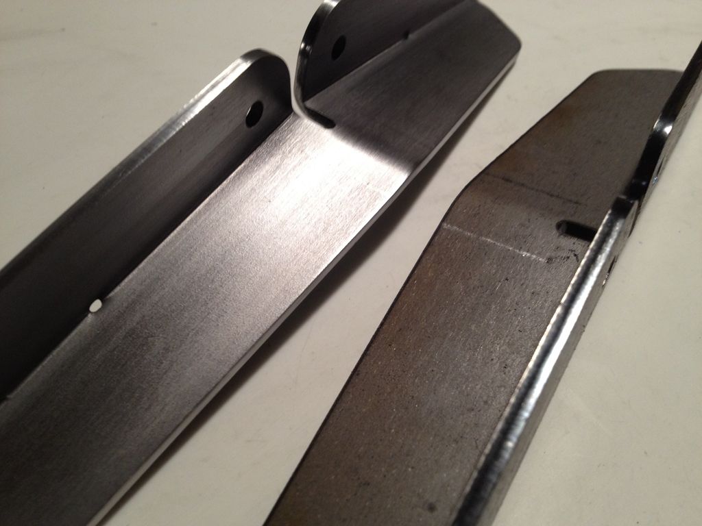
In these pictures you can see the difference between the prepped steel and the raw steel from the laser. There is a carbon build-up on the laser cut edge that needs to be removed as well as the oils from the surface...
After this step, I started to design and build a paint booth to use for painting all of the black parts. It was about this time that I started to think that paying extra to have all of the black pieces powder coated as well might be a way to make up some of the lost time as well as allow me to focus on tapping the holes and finishing the aluminum. I will finish up the paint booth at some point, but I think it is definitely the right decision to have these coated as well.
First step in building the DIY Paint Booth...
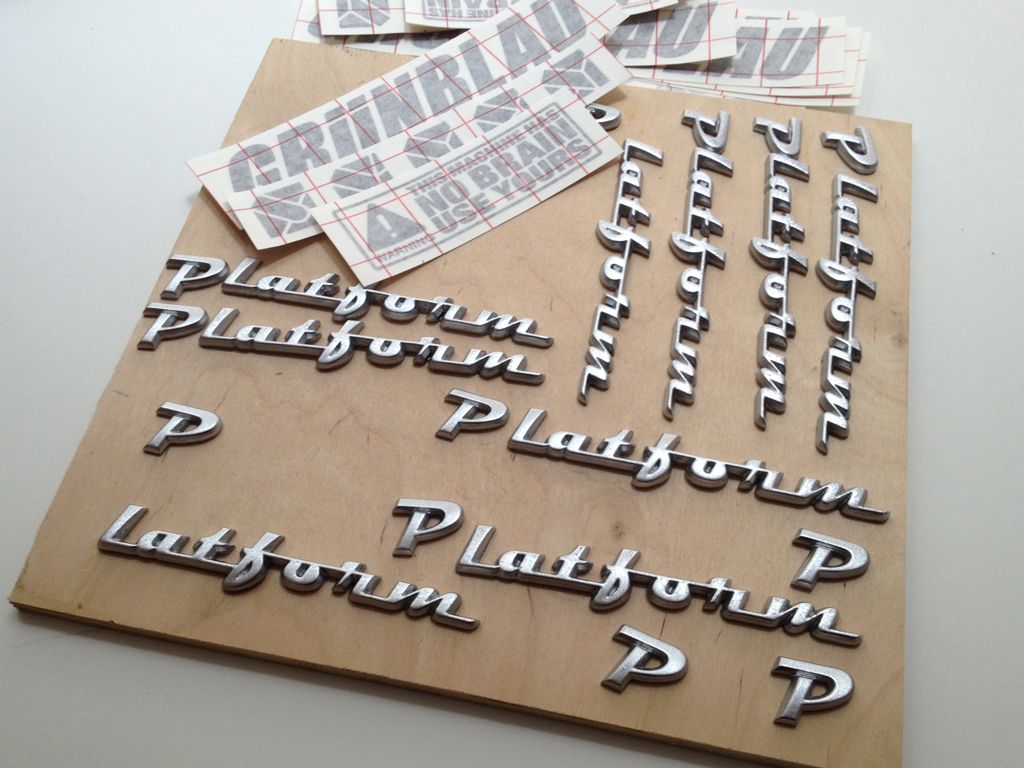
I still needed to cast all of the logos and cut the vinyl decals. In between tapping holes, I cast the logos and painted them. Here is the process...
Final painted logos and decals...
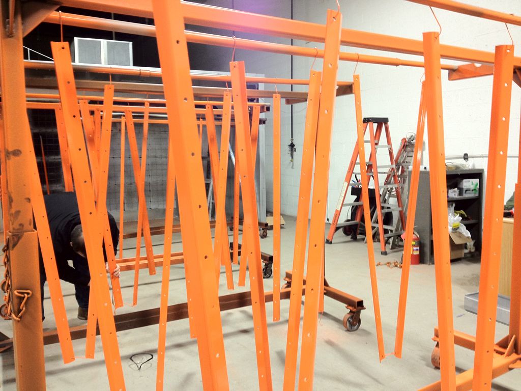
With the decision made to pay the extra to powder coat the black pieces as well, We loaded up a Uhaul with all of the steel to deliver it to the powder coaters and then I began prepping and tapping the aluminum.
For future runs, I am looking into having these holes tapped at the waterjet place as I underestimated the time it would take to do all of these holes. I had also changed the hole sizes in the Z Axis plate to 10-24 instead of 1/4-20 so that Ahren's one piece spindle clamps could be used. This made tapping a bit more challenging.
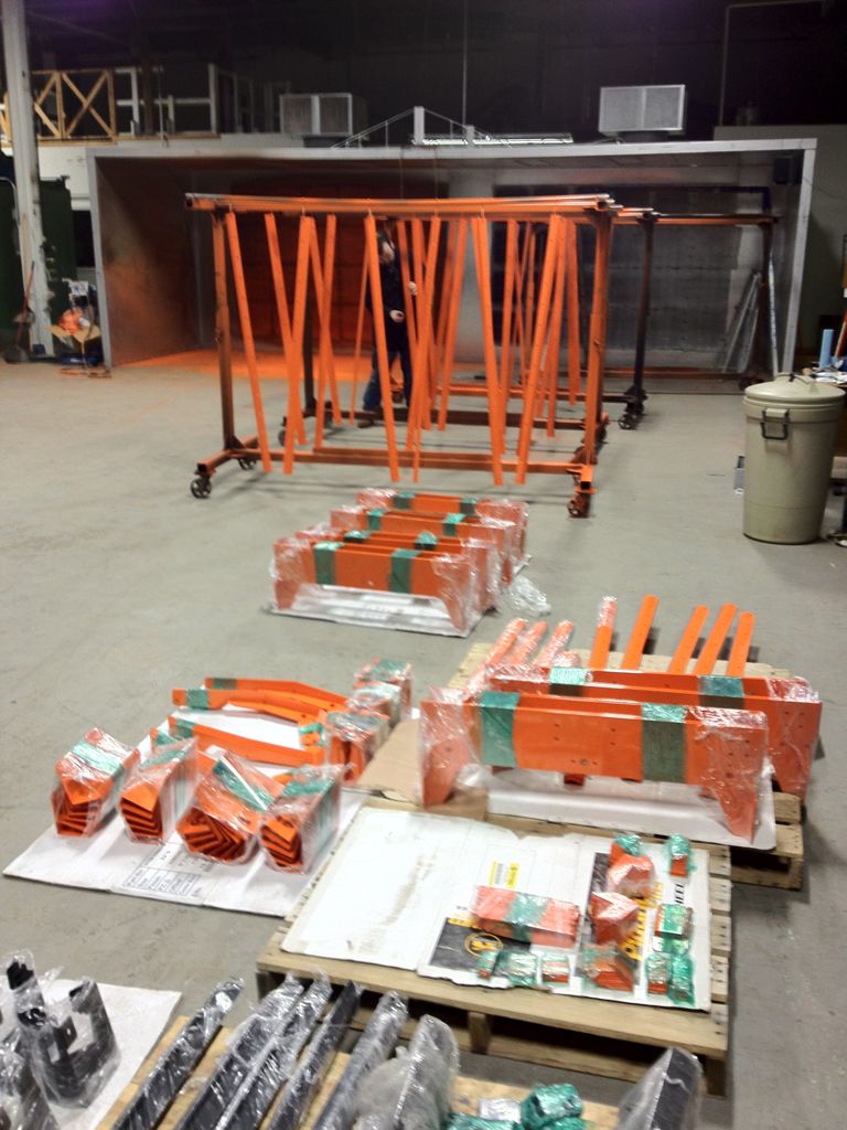
A week after dropping off the steel for PC, it was ready to pick up, 1250 sq ft. of orange. This is more sq footage than my last apartment!
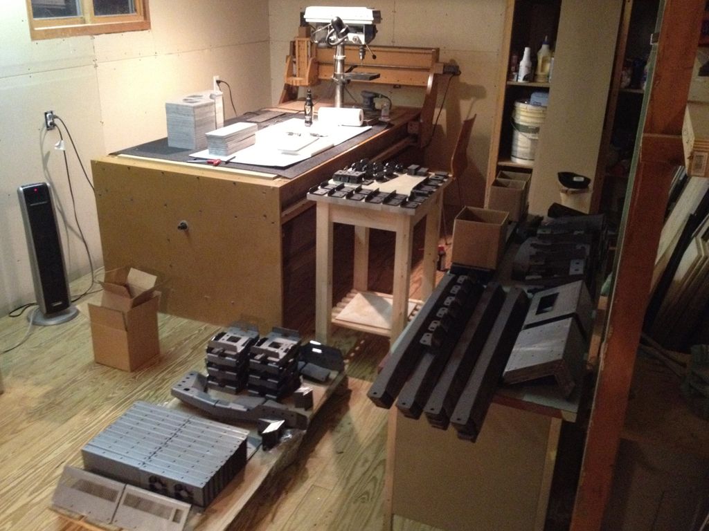
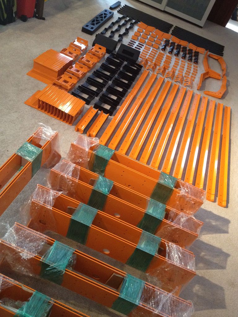
Here are all of the parts sorted into the 12 kits on the floor in my studio...
Now with the ability to mockup the final shipping dimensions, I found that everything would fit in a 16”X16”X36” box that would weigh 90 lbs and a 65” shipping tube that would weigh about 40 lbs. Knowing this, I ordered the shipping materials and began packing up the local machines...
The first kit was delivered on February 15th. The 5th local machine was delivered on February 23rd and was operational on the 26th. He made his first cuts on the 9th of March! 3D surfacing in aluminum no less!
Here is his pic...
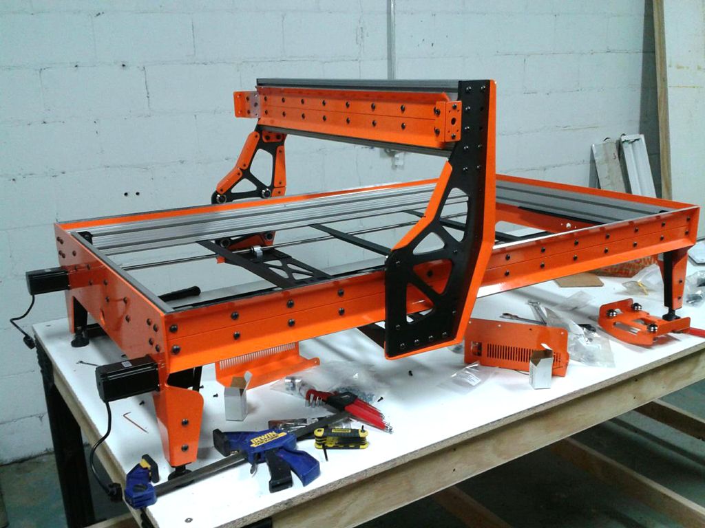
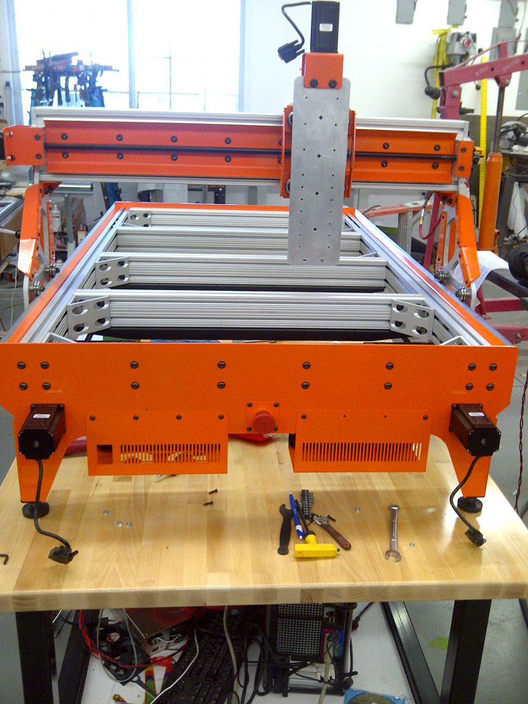
Here are two other people's builds that are getting close at this point! I might have to look into doing an all black edition in the future!
I think there are some exciting things on the horizon! I know a few people in this run are considering looking into Plasma cutting, and I want to see if I can add a rotary axis in the not too distant future. Someone else is looking into attaching a heated bed and an extruder head.
I have learned a lot so far in this process! There are a couple things that I will do differently for subsequent runs of kits. For example, I completely underestimated the amount of tapping. I know I did this all by hand and that I could invest in a tapping head, but I am currently getting it quoted to have it done in house at the place that waterjet cut the aluminum. This would save me a huge amount of time and the added benefit that if they break a tap off in the piece, they can just cut another one on the spot. The matte black powder coating for the black pieces was the correct decision. We are also working with the powder coating company to resolve some issues due to one of there ovens not heating evenly and I will likely end up sourcing another company for PC. I am also trying to figure out a better solution than Uhaul for moving the parts. I am looking forward to continued feedback from the people in the Initial Run and hope to be doing another run of Platforms soon!
That's it for now!
:cheers:
Brian
Results 1 to 20 of 30
-
03-17-2013, 12:50 AM #1
 Registered
- Join Date
- Jun 2008
- Posts
- 203
Latest news on the Grunblau Platform CNC
-
03-20-2013, 08:20 AM #2
Registered

- Join Date
- Dec 2012
- Posts
- 57
Are you going to do another run in the near future?
-
03-20-2013, 12:11 PM #3
Registered
- Join Date
- Nov 2006
- Posts
- 20
Just brilliant. I am definitely on board for your second run!
-
03-25-2013, 05:26 PM #4
Gold Member
- Join Date
- Sep 2006
- Posts
- 1738
Simply amazing!
-
04-03-2013, 01:55 AM #5
Registered
- Join Date
- Jun 2008
- Posts
- 203
Thank you very much for the comments!
I somehow missed including the images of all of the parts wrapped and in the Uhaul before the PC! Well here they are, better late than never...


I also received an image update for one of the machines. Looks great with a spindle! I wish I had 220 in my shop!

Looks like the VFD would fit between the 'saddlebags' I need to look at designing a bracket for this...^^^
BTW- In case you are wondering, he custom painted all of the aluminum textured black.
Very soon! If interested, please be sure to email me as this is the only way I can keep everyone in the loop! Originally Posted by dotmkr

Cheers!
Brian
Brian(dot)Oltrogge(at)gmail(dot)com
-
04-03-2013, 03:03 AM #6
Registered
- Join Date
- Aug 2011
- Posts
- 999
FWIW, I ran a 240V lathe with VFD for years on a 2kVA transformer from a 120V outlet. Worked just fine until I finally got a direct 240 V line. Originally Posted by Grunblau
-
04-03-2013, 09:36 AM #7
Registered
- Join Date
- Dec 2012
- Posts
- 57
I am in...Thanks Brian. See my email. I am going to go paint my wall black and orange now. :banana:
-
04-07-2013, 05:48 PM #8
Registered
- Join Date
- Dec 2012
- Posts
- 57
Can someone recommend a spindle and whatever else I need to run it. I have 220 i my shop and will be getting a Platform in June. I guess I would prefer to go with the spindle right off the bat rather than starting with a router and then changing.
Also, if anyone has drawn up a plan for a platform under the Platform that has storage for sheets and parts please post it if you will. Thanks
-
04-07-2013, 06:21 PM #9
Registered
- Join Date
- Jun 2008
- Posts
- 203
Hey Ken- Originally Posted by dotmkr
Here is some information that one of the guys (Steven H) put together when he spec'd out his spindle set up. I hesitate to post full names, but other people are more that welcome to weigh in!
I will likely try to compile this information into the assembly document in the future.
Hope this helps!
Here is what I bought.
UgraCNC Contact: Andy I bought his 2.2kw water cooled spindle and 12vdc pump.
CNCRouterParts I bought the 80mm spindle mount.
EnergyControl.com - HVAC and Building Automation Controls Since 1978. bought the Fuji FRN003C1S-7U VFD you can also use
the 002 and save $45.00, I buy from them a lot great price
Ebay Wavedaynamic 240mm cooler. Search ebay for CNC waterpump, cnc
cooler it doesn't take much to keep the spindle cool.
The Fuji will interface with little work into the Gecko and Mach3. Speed is
controlled by Mach3 as is starting and stopping.
I bought another switching power supply for the 12vdc to run the pump,
relays and fans. Search ebay 12volt DC power supply.
If you go with a fan cooled spindle then the minimum speed will have to be
upped to keep the unit cool, but you make the install much simpler. The fan
units are noisier but still nowhere near a router.
If you are searching for a VFD make sure it will, run off single phase,
0-400hz, take remote control. The Fuji at $277.00 is a great unit and you
will find it for $500+ from some shops.
Brian
-
04-07-2013, 09:06 PM #10
Registered
- Join Date
- Dec 2012
- Posts
- 57
thanks that is informative.
Here is one from buildyourcnc I wonder if it will interface with Mach 3? http://www.buildyourcnc.com/item/spi...kw-spindle-vfd
-
04-08-2013, 02:56 AM #11
Registered
- Join Date
- Apr 2013
- Posts
- 0
dotmkr, there isn't much info on their web site about the VFD. To remote control it they should list PID control in the specs. This is how you control the speed with Mach3.
The Delta and Fuji are the ones I see around the most.
I'm out in the field for 30+ days but I do have e-mail and web access.
Steve H.
-
04-08-2013, 07:50 PM #12
Registered
- Join Date
- Dec 2012
- Posts
- 57
Thanks. If you have a specific recommendation you can email me or if it is ok post it here. Originally Posted by SPH01
-
04-09-2013, 07:48 AM #13
Registered

- Join Date
- Jun 2012
- Posts
- 0
You are great designer and engineer, that is rare. Your machine look very nice.
Lucashttp://www.fightech.blogspot.com
-
04-16-2013, 06:51 PM #14
Registered
- Join Date
- Apr 2013
- Posts
- 0
Brian, just sent you an email but wanted to get in touch with you on here as well. Keep the updates coming!
-MD
-
08-09-2013, 02:57 PM #15
Registered
- Join Date
- Oct 2010
- Posts
- 83
Question
Brian,
I added my name to your next run of Platform. In the mean while would you have time to post a basic dimensions sketch of the Platform CNC. I.E. foot print, height of the table, overall table size, cutting area X,Y,Z? I have a Regenerative Vacuum Pump that should handle the Platform table size. Have you looked into using a vacuum table?
-
08-11-2013, 11:16 PM #16
Registered
- Join Date
- Jun 2008
- Posts
- 203
Thank you very much for your comments! Originally Posted by Kazik_Wichura
I wish there was more time in the day! I have a couple new things to share in the next weeks, but if you emailed me, keep an eye out for an announcement for the next run of kits! Originally Posted by -Weps
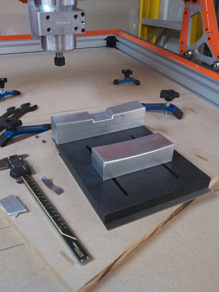
Absolutely! I initially was developing my first insert as a vacuum table, then Makerfaire happened and I am currently just using bolts and double sided tape. You can see the vacuum top below on the torsion box. I have purchased t-slot inserts from Rockler and will likely go this route for my next insert. I am continuing to also develop the plasma table as well... Originally Posted by gene8522
Here are some overall dimensions for the machine from a page in the assembly document that I provide with the machine..
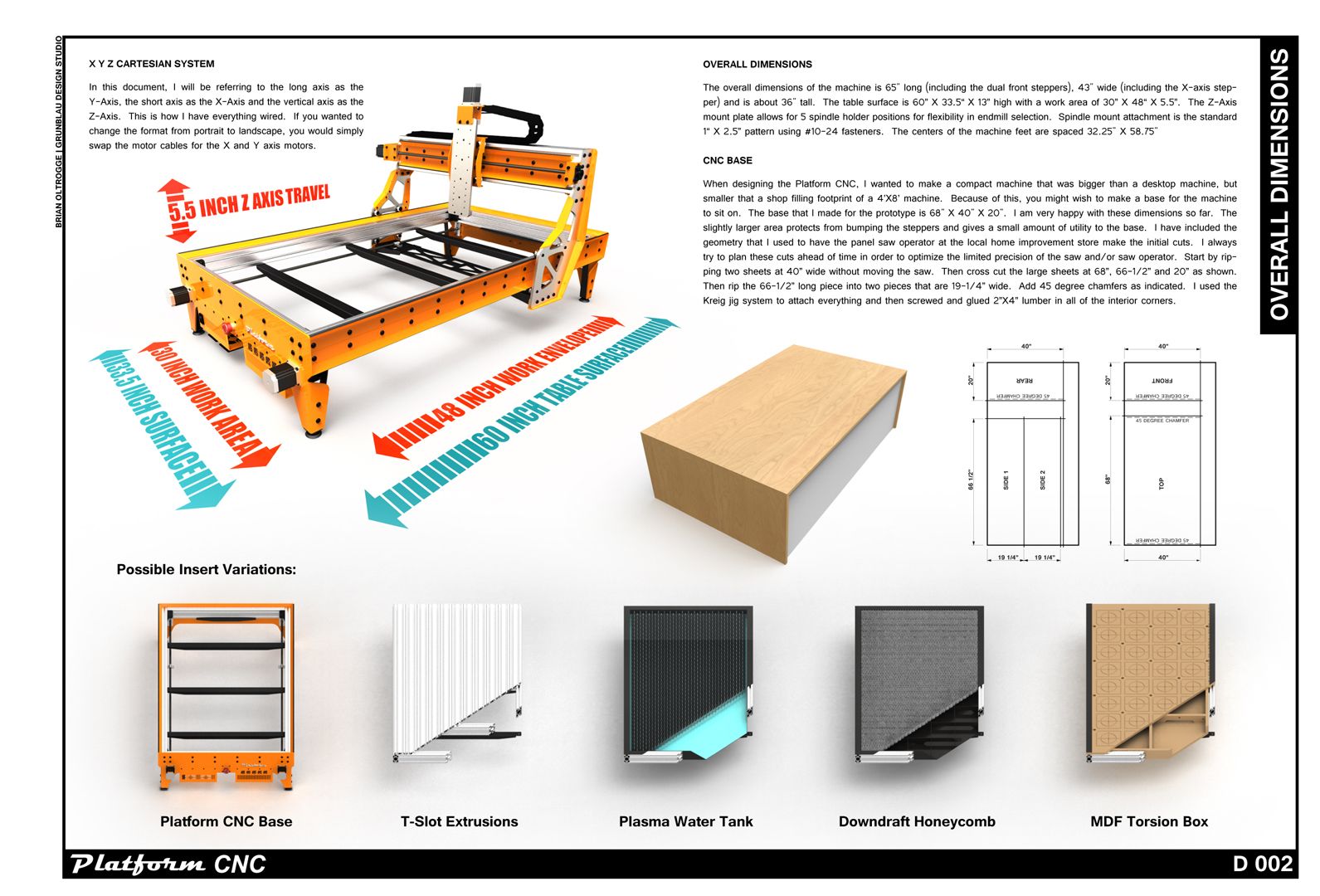
(right-click, open image in new tab)
The internal void space of the table is 30-1/2" wide X 57" long X 3.75" tall including the 3/4" thick top..
Hope this helps!
Brian
-
08-12-2013, 01:33 AM #17
Registered
- Join Date
- Oct 2010
- Posts
- 83
Thanks Brian,
Just one question...... How high is the top of the table from the bottom of the feet?
-
08-12-2013, 02:51 AM #18
Member
- Join Date
- Dec 2007
- Posts
- 2134
Words just don't express what a stunningly beautiful machine you've designed there Brian, I'd have one for on show in my lounge room if I could! Although the wife may have something to say about that.
cheers, IanIt's rumoured that everytime someone buys a TB6560 based board, an engineer cries!
-
08-13-2013, 08:16 AM #19
Registered
- Join Date
- Jun 2011
- Posts
- 39
Absolutely stunning... If only I was in America...
I'm guessing the cost of shipping to Australia would be prohibitive...
:violin:
-
08-13-2013, 08:43 AM #20
Banned
- Join Date
- Aug 2013
- Posts
- 8
Just one question...... How high is the top of the table from the bottom of the feet?


 Reply With Quote
Similar Threads
-
Grunblau (Rustbelt) Platform CNC [build log]
By Grunblau in forum DIY CNC Router Table MachinesReplies: 198Last Post: 04-25-2017, 05:14 PM -
Grunblau Platform CNC Groupbuy...
By Grunblau in forum DIY CNC Router Table MachinesReplies: 11Last Post: 10-14-2016, 03:39 PM -
latest Tormach news letter...
By SomeWhatLost in forum Tormach Personal CNC MillReplies: 4Last Post: 06-04-2013, 09:08 PM -
Latest news!
By widgitmaster in forum Community Club HouseReplies: 1Last Post: 03-03-2009, 09:59 PM -
Watch latest cnc news here at http://cnc-machines.org/news
By cncmachines in forum News AnnouncementsReplies: 1Last Post: 11-03-2008, 06:24 PM
