


hi
so i was looking at the makerbot replicator 2 and fancied having a go at designing my own printer. ive pretty much finished a solidworks model. dont want to do anymore until ive had some feedback on how ive done it. as im not sure its a very suitable/practical way.
i liked the style of the makerbot so i used that as a base for my design
the main chassis has been modelled to be some sheet metal, currently set to 1mm, then i though i could just sport weld it together in the corners.
for the linear bearings ive designed it to use bronze bushes, but im not sure if this will allow smooth movement. the bushes will just pr pressed into an aluminium block.
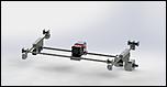
for the Y axis sliders ive got some nylon bushes to hold the bars for the X axis. im not sure if this is a good idea or if it will work with the sheet metal slider design ive got.
the y axis motor is in a similar position as in the makerbot, so ive got some shafts to move the motion to the other slider belt on opposite side of printer. the bars are suspended by some small bearings 5x10x4 which are held in some aluminium mounts which screw to the top, not sure if ive gone ab bit over the top with them though, thers 2 for every shaft
any feedback would be helpful, hopefully ill be able to build it one day


Thread: new printer design
Results 1 to 20 of 33
Hybrid View
-
03-25-2013, 11:18 PM #1
 Registered
- Join Date
- Apr 2011
- Posts
- 27
new printer design
-
03-25-2013, 11:51 PM #2
Registered
- Join Date
- Nov 2008
- Posts
- 643
Most of your drawings can't be displayed.
on bronze bearings vs ball bearings I don't think you can beat a ball bearing for accuracy (low clearance) and smooth rolling.
However I think you could get just about any type of bearing to work if you are willing to tune it. Ball bearings work well out of the box.
-
03-26-2013, 10:42 AM #3
Registered
- Join Date
- Apr 2011
- Posts
- 27
i thought if i used bronze bearings it would be cheaper and ide be able to make the design more compact
ive tried adding the photos again:


-
03-28-2013, 12:59 AM #4
Registered
- Join Date
- Nov 2008
- Posts
- 643
Great models. The bearings should work as long as they arn't tight on the shaft. I'm not sure why you arn't considering the ever popular LM8UU or larger, which are very cheap. Just a comment on your design, why wouldn't you put the Y axis motor up near or at the center of the Y axis drive shaft? Also why wouldn't you put the X axis motor on the outside of the X axis range? Seems strange to let the extruder platform possibly hit the X axis motor.
-
04-18-2013, 08:30 PM #5
Registered
- Join Date
- Apr 2011
- Posts
- 27
at the minute ive got some custom sized ones, id'e have to get them machined, just brass tube i think i put it. so ill try it with 2 short ones in either end of the block and just one long one. if i remember right i put 8mm shafts in.
ide try and get them to be a tight fit, preferably, i haven't put any grub screws to gold them in place since i didn't think they would be necessary
ahh ok, understand now. i thought with 2mm sheet metal i wouldn't get much flex or distortion. ill have a play, see what i could put in, preferably something quiet light, but would rather avoid aluminium, to keep machining costs down.
if the belt pulley is inline on the opposite slider it shouldn't flex should it? ill have the motor bracket spot welded to the main slider bracket, i think it should hold it securely.
i mean ill have plenty of room for the switches, when i positioned it to its extreme positions in the cad model it came into contact with brackets and mounts, so ive got plenty of room to mount the limit switches, without having to add extra space for them.
ill have a look at the firmware later if i get chance. don't want anything too ridiculously complicated.
ill try to start sourcing parts too, may take me quiet a while to gather everything i need if i build it.
any tips what features i should include in it, to go with the short list i have so far: LCD, simple navigation, e-stop, light up build area, SD card, what else is liked by the people?
thanks
rob
-
05-05-2013, 12:19 AM #6
Registered
- Join Date
- Apr 2011
- Posts
- 27
i liked the price of it, much better than the thermocouple i originally found.
ill start uploading some of the wiring diagrams and board layouts i have.
anyone know anyone that can tell me if the schematics are correct?
rob
-
03-30-2013, 09:19 PM #7
Registered
- Join Date
- Jan 2006
- Posts
- 114
@homer
verry nice cad files.
Have you also cad files for the extruder?
The pictures are looking real nice, how much time to draw these files?
What types are the belt you are using?
Thanks,
Pierke
-
04-29-2013, 12:12 PM #8
Registered
- Join Date
- Apr 2011
- Posts
- 27
not done much on the design ive got recently, but i hav made some progress with electronics.
ive decided im going to use the arduino electronics. this way i can personalise it to my design and look i want to get, as well as make the design more compact.
ive made most the schematics for the parts i need, and found the components im using for them. ive just got to make the schematic for the motherboard, whiich shouldnt take too. then ive just got to make the pcb layouts and find the rest of the components ill need.
is it best to have the power supply converter built into the printer or have it as a separate box? dont know if that makes sense
will put another update soon ish hopefully
rob
-
04-29-2013, 12:24 PM #9
Registered
- Join Date
- Jan 2006
- Posts
- 114
Are the Arduino pcb not ready?
Can you put a few pcb together?
I'v read elsewhere that some guys use a temp. controller from Velleman Kits.
Nice work!
Pierke
-
05-05-2013, 01:43 AM #10
Registered
- Join Date
- Apr 2011
- Posts
- 27
this is what i have so far
rob
-
03-31-2013, 04:28 PM #11
Registered
- Join Date
- Apr 2011
- Posts
- 27
ill make sure to get them bored slightly bigger than the shafts. i looked at them, when i modelled them they were too big for the size of some of the sliders, and the bushes were easier to mount. ill try having a play round with the x axis motor mount and sliders, see if i can get it out of the range. dont understand what you mean about the y axis motor position though. with the setup at the minute it has a pretty big build area. dont know if the z axis slider will be strong enough but at the minute it has a build area of about 250 x 145 x 185 ish.
which bit of the extruder? ive made rough cad drawings for pretty much all of it. i havent found components for the extruder so i havnt been able to make proper models for it.
once i got into it it didnt take too long, a day at the most working on it properly.
Synchroflex® Timing Belts - T 2.5 / T 2.5-DL (6MM)
was thinking of using these belts the T2,5 ones, they small and there quiet cheap .
-
03-31-2013, 07:02 PM #12
Community Moderator
- Join Date
- Mar 2003
- Posts
- 6855
Subscribed
looking good!
-
04-30-2013, 08:29 AM #13
Registered
- Join Date
- Apr 2011
- Posts
- 27
well i was going to but the arduino and boards ide need, but when i was making a layout for the navigation and lcd panel i got a bit carried away and changed my mind and decided to make layouts for everything
rob
-
04-30-2013, 09:25 AM #14
Registered
- Join Date
- Jan 2006
- Posts
- 114
Hello Rob,
can you make the platines by yourself (engraving or so?)
Pierke
-
06-10-2013, 01:19 PM #15
Registered
- Join Date
- Apr 2011
- Posts
- 27
hi all, not really done much recently, finished some prototype boards that im gona use before designing/building the mother board, found all the components for them too. cant do any building yet though since ive not got any money to buy anything, still job hunting, so probably not gona be able to do anything for a bit. may have a look at the cad model and see if theres anything i can improve, apart from that i think im just waiting on a job.
thanks
rob
-
05-11-2013, 08:55 PM #16
Registered
- Join Date
- Apr 2011
- Posts
- 27
thanks pierke
still not finished the motherboard though, i need to find parts i can use
since its based on the arduino mega board would it be a good idea to make a prototype in small sections so i can test it easily before making the final thing?
rob
-
03-31-2013, 10:09 PM #17
Registered
- Join Date
- Jan 2006
- Posts
- 114
We are looking to your next pictures.
Nice work! :-)
-
04-01-2013, 06:30 PM #18
Registered
- Join Date
- Apr 2011
- Posts
- 27
did some work on the z axis today.
again using sheet metal, ive changed to 2mm throughout the design. not sure if it will be able to take the weight of the models though
uses a nema 17 linear motor
the plate on the slider isnt the build platform, bolts will go through it so the actual build platform can be levelled off.
will be spot welded again, hopefully by using the shape i have it should make it stronger, and not bend when larger models are built on it
the lead screw will be fixed in at the top with a bearing so ive made a quick bearing mount for it, dont have a bearing yet so thats not its definite size
what you all think?


-
05-01-2013, 02:14 PM #19
Registered
- Join Date
- Apr 2011
- Posts
- 27
im guessing you mean pcb.
i cant make them myself, ill probably use oshpark to get them made
ill get the diagrams and layouts checked before i get anything made though
rob
-
05-01-2013, 10:16 PM #20
Registered
- Join Date
- Jan 2006
- Posts
- 114
Hello Rob,
yes i've seen Oshpark, there price is not expensive.
Its a good opinion to double check the diagrams.
I wish you verry mutch succes, it looks all verry good!!
Pierke
P.s.:i'm looking forward to your next post!

 Reply With Quote
Similar Threads
-
router/3d printer 1x0.7x0.3meter modular design
By watanabe in forum DIY CNC Router Table MachinesReplies: 12Last Post: 06-05-2011, 03:58 AM -
Converting a laser printer into a 3d laser printer
By João Carimo in forum Uncategorised MetalWorking MachinesReplies: 22Last Post: 04-30-2011, 09:56 PM -
design grad project: new breed of CNC design, need input
By nicanor76 in forum DIY CNC Router Table MachinesReplies: 11Last Post: 09-22-2009, 10:53 PM -
Canvas printer design hurdle
By Azazyel in forum Printing, Scanners, Vinyl cutting and PlottersReplies: 5Last Post: 08-28-2008, 12:26 PM -
Finding Engineering Design Software For Automatic Machine Design
By hellokitty in forum Uncategorised CAM DiscussionReplies: 0Last Post: 01-06-2008, 07:39 AM
