


What exactly are you trying to do? What are you going to use it for?Originally Posted by Wiggles84

Thread: Andrew's G07040 build
Results 121 to 140 of 241
-
06-05-2014, 04:48 PM #121
 Registered
- Join Date
- Oct 2004
- Posts
- 298
Re: Andrew's G07040 build
YouTube Channel: https://www.youtube.com/c/RobertCowanDIY
-
06-05-2014, 04:58 PM #122
Registered
- Join Date
- Sep 2012
- Posts
- 323
Re: Andrew's G07040 build
The stuff I already have will cover the 5/32 (4MM) hose on the oil system. I was thinking it would also be a good protector for the motor wire from hot chips and or rubbing. Originally Posted by cowanrg
I think the od or my wire is around 6M?
Andrew
-
06-05-2014, 05:02 PM #123
Registered
- Join Date
- Oct 2004
- Posts
- 298
Re: Andrew's G07040 build
Ah. What about something like this.
It's amazing for resisting wear, very flexible, easy to use, and cheap.YouTube Channel: https://www.youtube.com/c/RobertCowanDIY
-
06-05-2014, 06:22 PM #124
Registered
- Join Date
- Sep 2012
- Posts
- 323
Re: Andrew's G07040 build
I use that stuff for a Digital Gear Indicator (DGI) kit I make for legends race cars. Originally Posted by cowanrg
I love the way it looks, but I'm not sure how it will hold up to chips. That's why the "spring tube guard" stood out to me.
Andrew
-
06-05-2014, 06:25 PM #125
Registered
- Join Date
- Oct 2004
- Posts
- 298
Re: Andrew's G07040 build
well, the techflex stuff is going to be excellent at wear and abrasion resistance. it might not hold up as well with molten metal chips, but if the metal shield gets really hot, won't it just then melt what's inside it? I really don't see you having in issue with chips melting your cables...
YouTube Channel: https://www.youtube.com/c/RobertCowanDIY
-
06-05-2014, 06:59 PM #126
Registered
- Join Date
- Sep 2012
- Posts
- 323
Re: Andrew's G07040 build
Well..... you see.... My issue is I like to over do things! It's something that Tool and Die Makers are known for. Weather it's good or bad is debatable!

Also 99% of the machining I do at work is on an bridgeport tree mill with an eztrek (sometimes a accurite millpower) controller in steel. Hot a$$ chips everywhere with no flood coolant.
Most of what I want to do is aluminum (under flood) and plastic in this machine. So the techflex would more than likely work. And would be cheap enough to replace every so often.
We'll see what I end up doing
Andrew
-
06-05-2014, 07:04 PM #127
Registered
- Join Date
- Oct 2004
- Posts
- 298
Re: Andrew's G07040 build
ah, so instead of using springs, why not something like this:
AFC Cable Systems 100 ft. 12-2 Solid MC Lite Cable-2104S30-AFC at The Home Depot
armored cable.YouTube Channel: https://www.youtube.com/c/RobertCowanDIY
-
06-06-2014, 03:17 AM #128
Registered
- Join Date
- Nov 2012
- Posts
- 220
Re: Andrew's G07040 build
I am using this to protect my cables and oil lines:
McMaster-Carr
-
06-09-2014, 09:03 AM #129
Registered
- Join Date
- Sep 2012
- Posts
- 323
Re: Andrew's G07040 build
Made a little more progress this weekend. Got the column back on after I machined it to gain a little more z travel and cleared the bottom of the dove tail for one of my fittings, crunched the first one :tired: .
I also played around with the oil line for the Z ballnut. I have (will have) the line coming in to the hole left by the hand crank, loop down the inside and then back up to the nut.
At first I started with some nuts to "weigh down" the loop. but they where not heavy enough and I went to a piece of cold rolled with a plastic inserted into it. I think it would work, but I think I'm going to try to use a spring to keep it toward the side
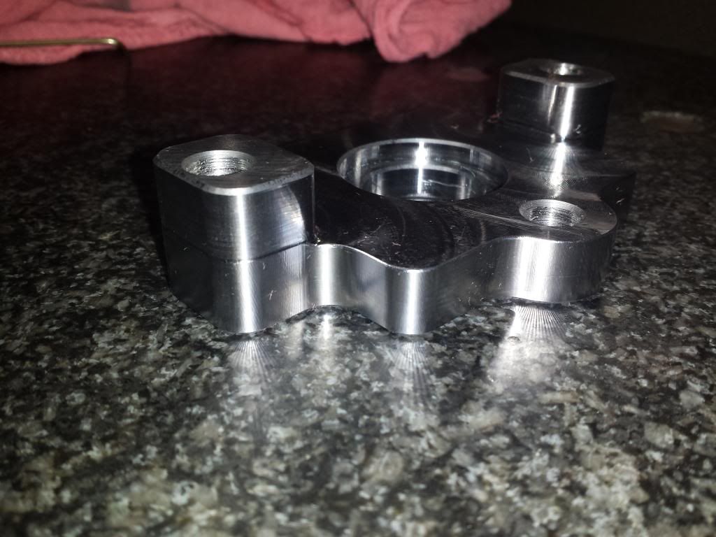
Made the first piece of the power draw bar that LacL designed
Andrew
-
06-09-2014, 07:17 PM #130
Registered
- Join Date
- Oct 2004
- Posts
- 298
Re: Andrew's G07040 build
I am tearing down my Z axis and getting the oiler setup for it. I'm actually mounting a manifold on the head of the mill that will supply oil to both the dovetails as well as the nut. Since the Z nut is connected to the head, I figured it would be best to have the line/manifold supply it from the head. I'll be either drilling a mount in the head itself, or routing it someway so that it's stationary with the head. The tube the supplies the manifold will move and be attached to a cable carrier. Does that make sense?
YouTube Channel: https://www.youtube.com/c/RobertCowanDIY
-
06-10-2014, 09:27 AM #131
Registered
- Join Date
- Sep 2012
- Posts
- 323
Re: Andrew's G07040 build
yeah I was trying to go that route at first. But there just wasn't enough room for any of the ideas I could come up with.
That's when I found the link to the site in the UK and they had everything I wanted to try what I currently have setup.
I to will be using a manifold to the two dovetails and the ball nut. just not sure where I'm going to put the manifold yet.
I really wish I had more time to play with this mill and get it up and running. Would have all the time in the world 5-6 years ago before the kids ! (chair)
Andrew
-
07-15-2014, 03:24 PM #132
Registered
- Join Date
- Sep 2012
- Posts
- 323
Re: Andrew's G07040 build
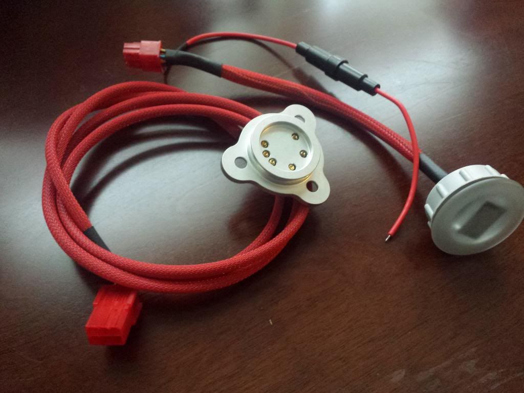
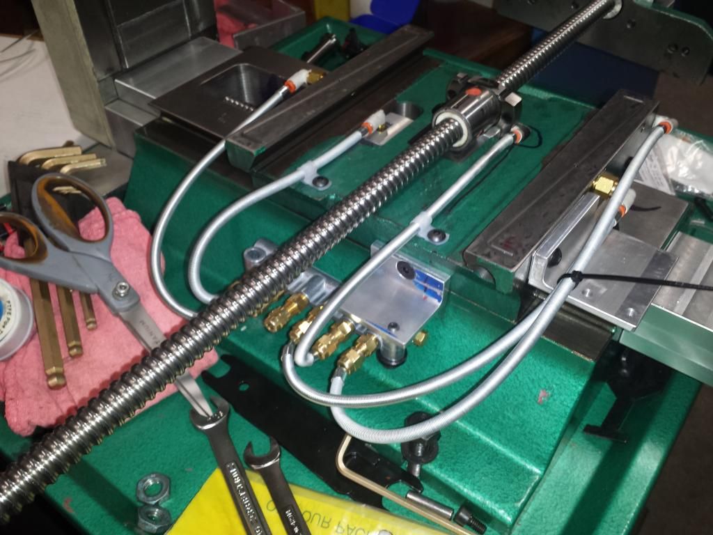
Did some work on my one shot oiler system. It may be overkill?
As it was.....
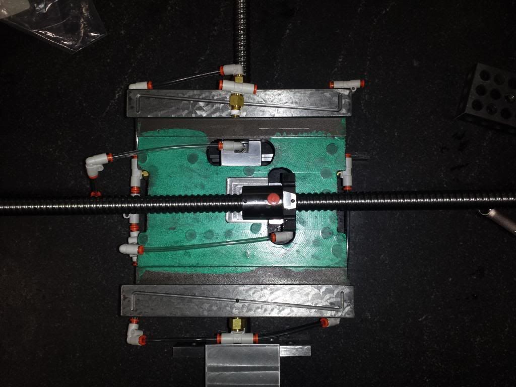
And now with the new stuff.....
Still need a few fittings to finish it up
Andrew
-
07-15-2014, 05:14 PM #133
Registered
- Join Date
- Oct 2004
- Posts
- 298
Re: Andrew's G07040 build
I don't think that's overkill, that's how it's supposed to be. Looks good. Do you have adjustment for each line on the manifold?
YouTube Channel: https://www.youtube.com/c/RobertCowanDIY
-
07-15-2014, 05:58 PM #134
Registered
- Join Date
- Sep 2012
- Posts
- 323
Re: Andrew's G07040 build
No adjustments, each line has its own one way metering valve! ( the overkill part
 )
)
So that's 6 valves for the X & Y saddle area. I have another manifold and 3 valves for the Z saddle and Z nut.
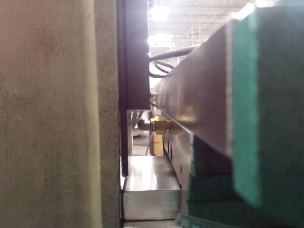
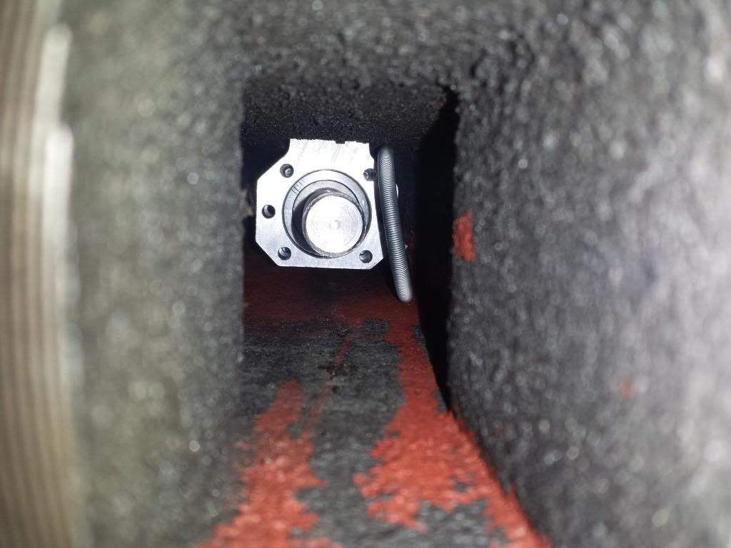
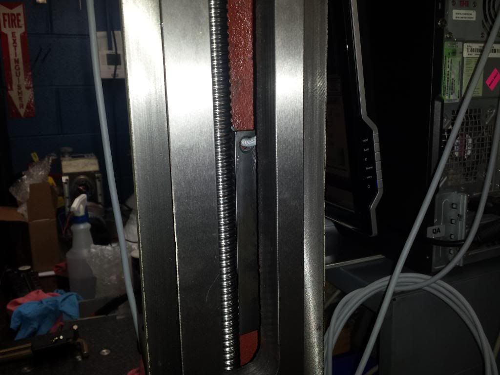
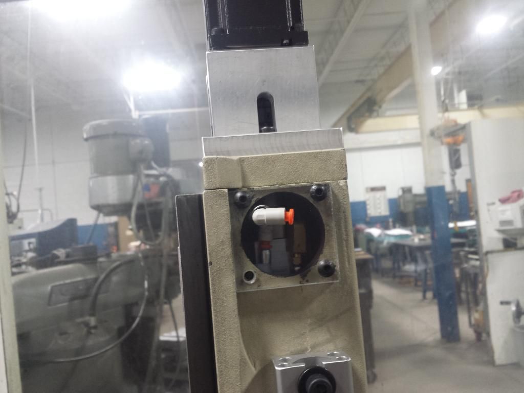
That last pic shows the connection for the Z nut. I have the line looping down the inside of the column and back to the nut. At the push to connect behind the acrylic, the line is held in place by a cable hold down. I have cycled the nut up and down 100+ times without it getting in the way. All the oils lines are covered with a "spring tube guard" to protect it for any wear that may occur during movement.
Andrew
-
07-15-2014, 06:01 PM #135
Registered
- Join Date
- Oct 2004
- Posts
- 298
Re: Andrew's G07040 build
ah OK, that should work well.
YouTube Channel: https://www.youtube.com/c/RobertCowanDIY
-
07-18-2014, 11:14 PM #136
Neuer Benutzer
- Join Date
- Jan 2013
- Posts
- 630
Re: Andrew's G07040 build
How about a small pulley anchored by a spring at the bottom of the column with just enough tension when the head is at the bottom to keep the fluid line tensioned and away from the screw.
-
07-18-2014, 11:55 PM #137
Registered
- Join Date
- Sep 2012
- Posts
- 323
Re: Andrew's G07040 build
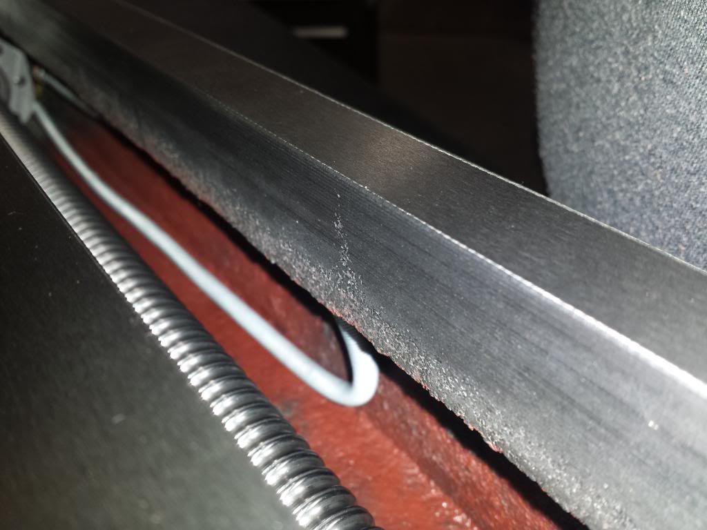
that's where I was heading next. But for whatever reason I twisted the line at the push to connector and that twist keeps the line against the side of the column.
The line is protected by a metal covering so a little rubbing should be ok. and the line never travels past the end of the screw.
Andrew
-
07-21-2014, 07:46 AM #138
Registered
- Join Date
- Sep 2006
- Posts
- 37
Re: Andrew's G07040 build
Hi Andrew
I wonder if you can help me please I am just starting to convert my BF20 to CNC I have got Hos's DVD and have bought the Automation Technology C7 ballscrews . The problem I have is how is the X nut fitted to the frame. The ballscrew mount in Hos.s drawings has no tapped holes to screw the frame to the ball screw mount . And olny has 2 pins on it. Do you just wedge the assembly into the frame. Also what is the dia of the tube needed to remove the Y ballscrew nut from the ballscrew.
Thanks
Bob
-
07-21-2014, 08:45 AM #139
Registered
- Join Date
- Sep 2012
- Posts
- 323
Re: Andrew's G07040 build
Hello Bob,
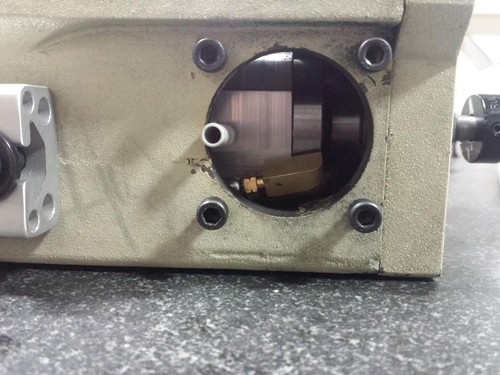
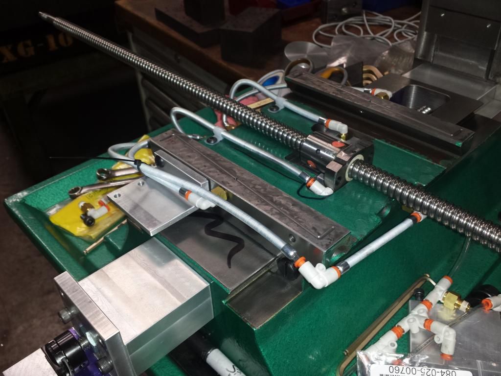
If I understand what you are asking about the X nut mount, Yes it gets wedged against the frame by the same bolts that wedge the stock lead nut.
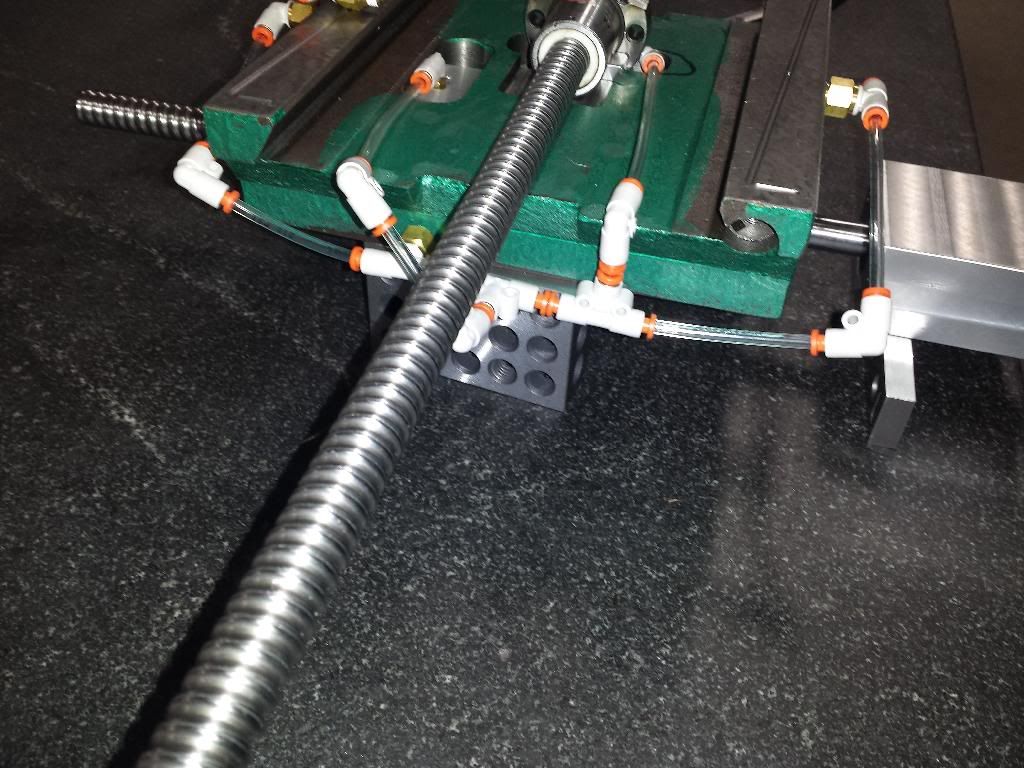
Looking at the pic below, the two bolts can be seen under the screw toward the bottom of the pic. this is the right side of the saddle when standing in front if the machine.
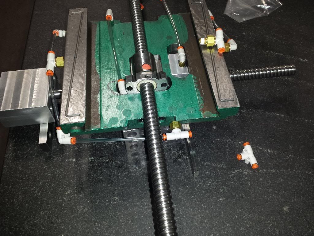
As for the diameter of the tube needed for removing the ballnut, I just measured the minor diameter of the screw and made my tube that size.
Hope this helps,
Andrew
-
07-21-2014, 07:43 PM #140
Registered
- Join Date
- Sep 2006
- Posts
- 37
Re: Andrew's G07040 build
Hi Andrew
Thanks for taking the time to reply that is exactly what I thought as regards the nut mount. It just seems strange that there are no positive locking screws to hold the mount .
Thank you for the tube dimensions. I can go ahead now . I may start a thread on how I do my conversion. But Idont know if another one on the BF20 is called for.
Thanks again
Bob

 Reply With Quote


Similar Threads
-
Andrew's G0704 CNC Conversion
By andrew2085 in forum Benchtop MachinesReplies: 12Last Post: 01-21-2013, 06:04 PM -
Mint's Build Aluminum/Steel Build thread.
By FreshMint in forum Maintenance DIY DiscussionReplies: 0Last Post: 10-31-2011, 04:18 AM -
Newbie - To build or not to build Router/Plasma Table
By dfranks in forum Waterjet General TopicsReplies: 10Last Post: 04-08-2011, 05:16 AM
