


Project :: Low Cost CNC
Welcome!!
Project Description :: This project start because i already sold my old CNC and need to make more space to my room. For this machine i will make it to do my hobby such as cutting acrylic , wood ,some thin aluminum or some PC side panel and i will make it as my coffee table.
Project By :: iD2
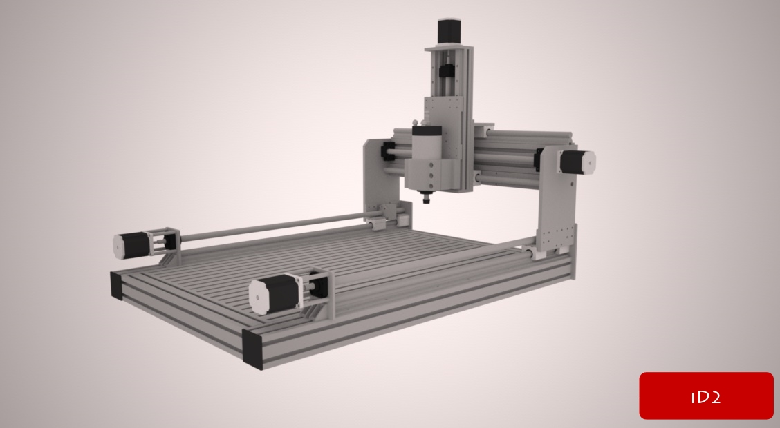
Final design (9th revise) ::
Specification ::
- X-Axis --> Working area 700mm
- Y-Axis --> Working area 500mm
- Z-Axis --> Working area 150mm
- X-Axis --> Using SBR Rail ,Dual ballscrew and drive
- Y-Axis --> Using SBR Rail
- Z-Axis --> Using Linear guide
- Overall dimension 1000x860mmx550mm
Results 1 to 20 of 44
-
07-05-2013, 03:48 PM #1
 Registered
- Join Date
- Apr 2011
- Posts
- 147
[Scratch build] :: Low Cost CNC - Working area 700x500x150mm (X,Y,Z) :: by iD2CNC
-
07-05-2013, 03:51 PM #2
Registered
- Join Date
- Apr 2011
- Posts
- 147
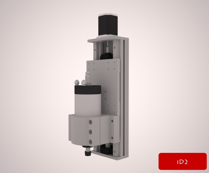
Before get my final design this my
Z-Axis design ::
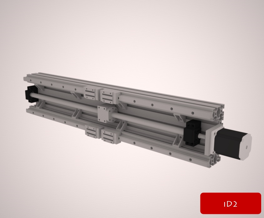
Y-Axis design ::
Machine by using Linear guide ::

1st revise by using SBR Rail ::

8th revise by using SBR Rail ::
-
07-09-2013, 12:11 PM #3
Registered
- Join Date
- Apr 2011
- Posts
- 147
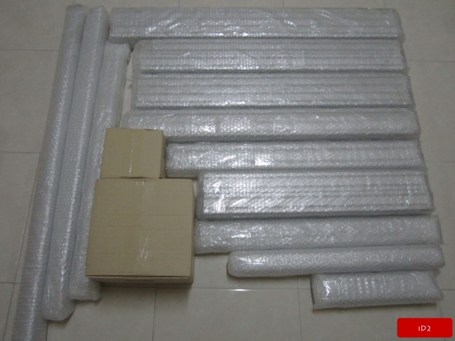
Just brought some parts and other are coming.
-
07-09-2013, 01:31 PM #4
Gold Member
- Join Date
- Jun 2004
- Posts
- 6618
Any of the designs should work pretty well. Take care to place the Z so that you can get to the spoil board. Looks a little high. Pictures of parts are looking good. Good luck with it and I will stay tuned.
 Lee
Lee
-
07-09-2013, 02:45 PM #5
Registered
- Join Date
- Apr 2011
- Posts
- 147
Thank you for your recommend. Originally Posted by LeeWay

-
07-10-2013, 06:30 AM #6
Registered
- Join Date
- Jul 2009
- Posts
- 419
The motors for x axis are mounted on an L plate (if you know what I mean), only supported on one end.
This introduces the risk of the plate bending under load, resulting in an s-shaped ball screw or at least extra stress on the balls-screw contact area.
Better stiffen that up some how!Sven
http://www.puresven.com/?q=building-cnc-router
-
07-10-2013, 01:37 PM #7
Gold Member
- Join Date
- Jun 2004
- Posts
- 6618
Right.
I think using a thicker plate than what is shown will handle that.Lee
-
07-11-2013, 02:45 AM #8
Registered
- Join Date
- Apr 2011
- Posts
- 147
Thank for your recomend. I forgot to update my last design that already fixed that issued.

-
07-11-2013, 03:24 AM #9
Registered
- Join Date
- Jan 2008
- Posts
- 1529
Some shields for the screws and rails will be a good idea
7xCNC.com - CNC info for the minilathe (7x10, 7x12, 7x14, 7x16)
-
07-11-2013, 04:11 AM #10
Registered
- Join Date
- Apr 2011
- Posts
- 147
Yes , i'll do it both shields and dust shoe. Originally Posted by pippin88
-
07-11-2013, 01:15 PM #11
Registered
- Join Date
- Apr 2011
- Posts
- 147
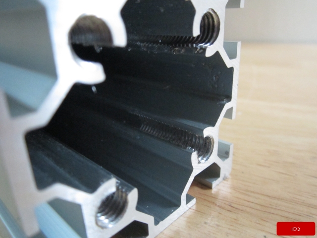
Aluminum profile already arrive.
-
07-11-2013, 01:18 PM #12
Gold Member
- Join Date
- Jun 2004
- Posts
- 6618
Then let the fun begin.
Lee
-
07-11-2013, 01:20 PM #13
Registered
- Join Date
- Apr 2011
- Posts
- 147
Update my lastest specification ::
Specification ::
- X-Axis --> Working area 700mm
- Y-Axis --> Working area 520mm
- Z-Axis --> Working area 120mm
- X-Axis --> Using SBR Rail ,Dual ballscrew and drive
- Y-Axis --> Using SBR Rail
- Z-Axis --> Using Linear guide
- Overall dimension 1000x860mmx550mm
-
07-12-2013, 03:50 PM #14
Registered
- Join Date
- Apr 2011
- Posts
- 147
Originally Posted by LeeWay

-
07-12-2013, 03:52 PM #15
Registered
- Join Date
- Apr 2011
- Posts
- 147
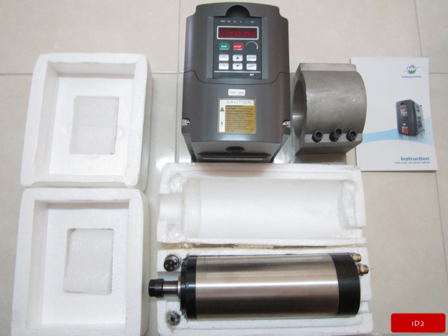
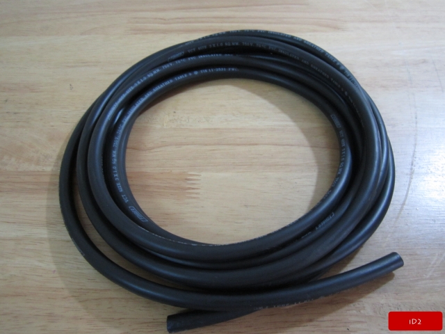
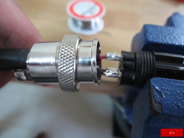
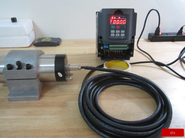
Spindle arrive, Custom add potentionmeter to font panel of inverter
Just got Water cooled spindle + Inverter + Spindle clamp. So today i do wiring and add Potentiometer to Inverter and then test them to make sure everything work fine and correct wiring.
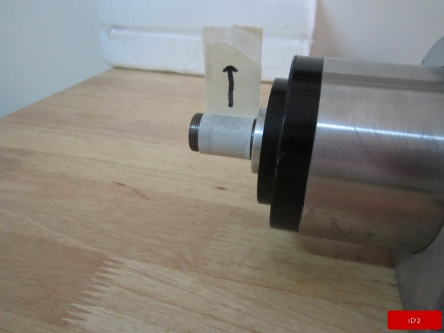
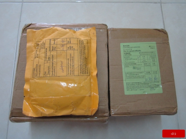
Item arrive ::
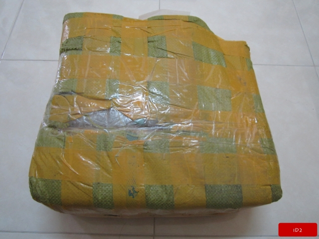
Unpack the package
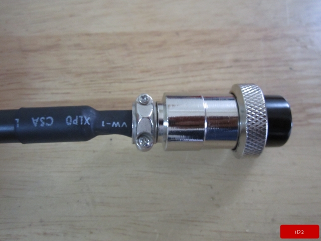
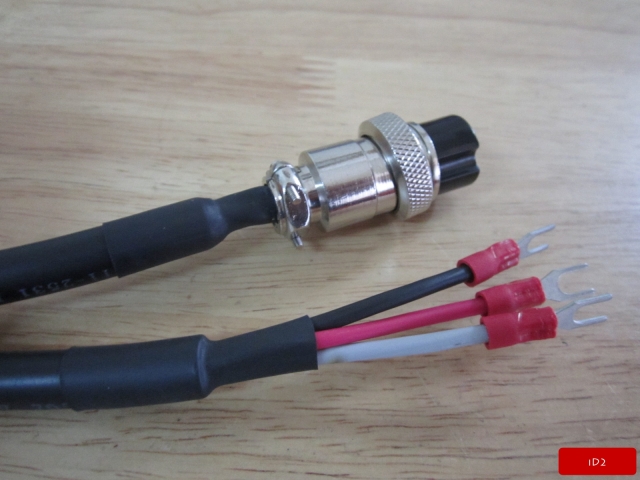
Start wiring ::
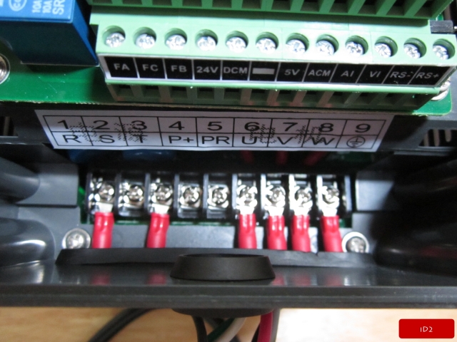
Note :: For single phase power use “R” and “T” but for Three phase power use “R” and “S” , or “S” and “T” , both will work fine.
After finish wiring then test run ::
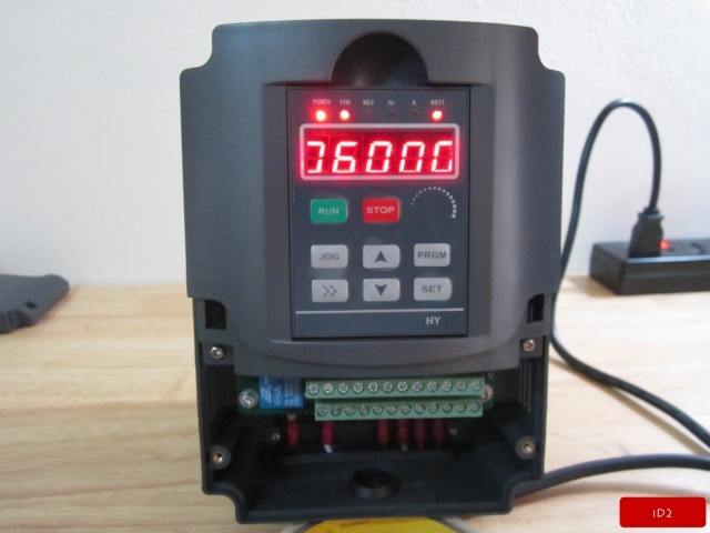
Note :: Before start run it VFD need to parameter setting.
- PD005 = 400 (Hz)
- PD004 = 400 (hz)
- PD003 = 400 (hz)
- PD008 = 220 (220volt)
- PD072 = 400 (hz)
- PD144 = 3000
This parameter need to set up before start run spindle. Other parameter see document.
After test , It work correctly and everything good so next i need to add potentionmeter to font panel of inverter , it already have socket for putting potentionmeter into it.
Done !!! lol
Video test here ::
-
07-18-2013, 05:54 AM #16
Registered
- Join Date
- Jan 2010
- Posts
- 5
Looking good. I really liked your last design. Very clean.
Have fun!
-
07-19-2013, 11:02 AM #17
Registered
- Join Date
- Apr 2011
- Posts
- 147
Originally Posted by CaveDog
Thank you.
-
07-19-2013, 11:04 AM #18
Registered
- Join Date
- Apr 2011
- Posts
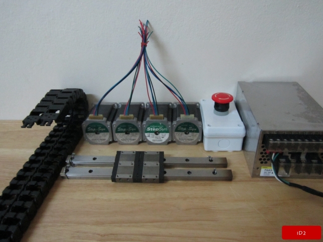
- 147
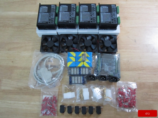
Now electronic kit just arrive and then i will go to wiring and test run stepper motor first and then i will go to drill and tap aluminum and aluminum profile , finally start assembly the machine.

-
07-23-2013, 06:13 PM #19
Registered
- Join Date
- Apr 2011
- Posts
- 147
After long time not update , just busy and have something to do. OK let's see some update progress and i think i will finish my machine not over 2 week.
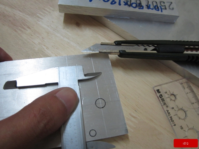
Tap aluminum profile ::


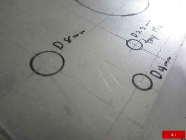
Mark drill & tap position of Z-Axis :: This can do 2 way, 1st like picture below , 2nd print my design as scale print but i choose 1st way.


-
07-24-2013, 05:34 AM #20
Registered
- Join Date
- Dec 2006
- Posts
- 73
Didn't see it in the thread, what size SBR rails are you using for the X & Y?
Chuck


 Reply With Quote
Similar Threads
-
RF-45 Hybrid Scratch Build
By migrusch in forum Benchtop MachinesReplies: 100Last Post: 04-24-2014, 11:18 AM -
PC modder Looking to buy or build a low to avg cost CNC with 2' x 3' work area.
By OrangeClockwerk in forum DIY CNC Router Table MachinesReplies: 10Last Post: 01-25-2014, 03:33 AM -
Working up a logo from scratch
By cncadmin in forum EnRouteReplies: 0Last Post: 06-06-2012, 05:50 AM -
First build from scratch
By Sockles in forum DIY CNC Router Table MachinesReplies: 7Last Post: 08-23-2011, 11:29 PM
