


Lots of goodies arrived today.
Hiwin rails and cars packaged nicely from Automation overstock
Steppers and drives. Also packaged nicely from CNC Router Parts.
Looks like I need to source a Parallel printer cable to connect smoothstepper to g540. Bummer...
Thread: Steve's 2x2 CNC Router
Results 21 to 40 of 201
-
08-08-2013, 10:19 PM #21
 Neuer Benutzer
- Join Date
- Jan 2013
- Posts
- 306
-
08-09-2013, 02:52 AM #22
Neuer Benutzer
- Join Date
- Jan 2013
- Posts
- 306
Made it back into the shop again tonight. Thought I would start finishing up items to do a rough fit of the components, starting with the x axis slides and building up from there.
I purchased tnut blank material from 8020 to mount the rails. Drilled and tapped them M5 on 60mm centers. Also using a 1-1/4 x 1/4" CRS bar to span the slot on the extrusion and provide a flatter base for the rails. The bars were pretty flat and I will surface grind if needed.
Attachment 195438
Tapping head again to tap 60 holes. Took 10 minutes for all the holes.
Attachment 195440
Rail spacers being drilled. 1/4" on X rails and 1/2" on Y rails. Y needed more space for ball screw.
Attachment 195442
Drilling holes to mount cars and mounting gantry. Added drilled and reamed holes for 1/8" dowels to align cars straight on plate. We do this on all the machinery we design and build. I did not add the small buttons that push the car to the datum dowels. Figured I could clamp then tighten the bolts.
Attachment 195444
These are the plates the gantry bolts to and bolts to the x slides.
Attachment 195446
Next time I will add the holes in the edges that allow ball nut to be mounted on X slides and gusset plates on the gantry mounts.
-
08-11-2013, 03:01 AM #23
Neuer Benutzer
- Join Date
- Jan 2013
- Posts
- 306
Finished up a bunch of parts. today. Stepper mounts, ball screw bearing blocks, ball nut mounts. Gantry braces etc..
Attachment 195704
Aligning cars while bolting to slide
Attachment 195706
Found out the Hwin cars do not retain the balls so must have a rail or the insert in place at all times. Only knocked out a couple so they were easy to put back in place.
Attachment 195708
Doing some test fitting of the assembly.
Starting to look like a router.
-
08-12-2013, 12:24 AM #24
Neuer Benutzer
- Join Date
- Jan 2013
- Posts
- 306
Did a little machining on the Y slide. Just needs a couple more holes.
Also tried out the Ethernet smoothstepper. No problems getting connected and sending data via Mach3.
-
08-18-2013, 10:14 PM #25
Neuer Benutzer
- Join Date
- Jan 2013
- Posts
- 306
Finally made it back into the shop. Finished up the Z and Y axis slides and the plate to stiffen the gantry.
Gantry mocked up with the Z Slide assembled. Found out i ordered the wrong length rails so I will need to place an order for a couple more rails.
Also need to add a small notch for the ball nut to clear the z Slide.
Attachment 196754
Adding the back plate will make the gantry plenty rigid. It is already weighing a lot. It is a load to lift in place by your self. Luckily it balances pretty well on the uprights.
Attachment 196756
Here you can see that I need the longer rails for the Z slide.
Attachment 196758
Also received the motor couplings. I ordered the larger versions so the motor mounts will need to be opened up slightly to clear.
The controller was powered up and had no problems getting all the steppers performing as expected. Once mounted up they can be tuned in.
The Ethernet Smoothstepper and G540 was easy to get going, Having the prewired motors and cables saved a lot of time.
-
08-22-2013, 02:38 AM #26
Neuer Benutzer
- Join Date
- Jan 2013
- Posts
- 306
Not a lot of progress past few days. Soccer season starting so many games to watch and photograph.
I did get my drawings all up to date with some last minute modifications. Tonight I dismantled everything to make modifications and clean up all the parts. Then I can begin the actual assembly.
Sent from my iPad using Tapatalk HD
-
08-26-2013, 02:26 AM #27
Neuer Benutzer
- Join Date
- Jan 2013
- Posts
- 306

Started the assembly process after hitting all the surfaces with RO sander and chamfering edges.
Attachment 197690
Base portion partially assembled and working on the x axis slides for the gantry.
Attachment 197692
Finish from RO sander, still not decided on if I am going to have the parts anodized.
Attachment 197710
Assembly of the mast for each side of the gantry
Both mast sitting in location
Attachment 197694
Main beam on gantry. Lots of fasteners to attach back plate and mast.
Attachment 197696
Gantry assembled
Attachment 197698
Mast and assembly joined and mounted on slides
Attachment 197700
Y axis ball screw mounted
Attachment 197702
Assembly of Y axis slide. Dowels to align cars.
Attachment 197704
Y axis slide with all the cars mounted
Attachment 197706
Mounted to gantry
-
08-28-2013, 03:11 AM #28
Member
- Join Date
- Dec 2007
- Posts
- 2134
I'm really enjoying watching this build Steve, very nicely put together mate. Too often you see here machines being built with extrusion that are a pile of bit's hanging out in space unsupported. It's very obvious from your build that you've spent a great deal of thought on rigidity and design, and it shows!
Nice to see a gantry properly braced for a change too!
Looks like your on the home stretch now, can't wait to see this one in action.
cheers, IanIt's rumoured that everytime someone buys a TB6560 based board, an engineer cries!
-
08-28-2013, 01:05 PM #29
Neuer Benutzer
- Join Date
- Jan 2013
- Posts
- 306
Thanks Ian,
Took a few steps backwards the other night. Disassembled all the slides and reassembled the cars with a rail to help keep them aligned and straight to the dowels.
Using the dowels only they felt a little snug on the rails. They are good now.
Just wish I had more free time to finish up. Getting really close to doing some movement. Have X and Y motors installed, just need to finish up the z axis.
Sent from my iPad using Tapatalk HD
-
08-31-2013, 05:45 PM #30
Neuer Benutzer
- Join Date
- Jan 2013
- Posts
- 306
Started out today with wrapping up a few odds and ends
Had to machine a pocket to recess the motor to allow the coupling to fully engage the ball screw.
Now fully engaged.
Did not machine enough ball nut mounts. Thought I would see how rugged a 3d printed version is.
Also testing out a printed stepper mount. Not as much force applied to this side.
Had a couple hidden screws, might change this on the design so car does not need to be removed.
Y slide mounted again......
Z Slide in place
Use these at work all the time. Never did get a T handle set for home.
Best $70 you can ever spend if dealing with Socket heads. Quickly pay for themselves in speed of use and frustration from other type allen wrenches.
And finally Some movement with the motors. (uploading as I am posting so might need to wait a few minutes)
Next up. Run through the travel extents making sure everything is smooth and not bound.
Then maybe some test cuts!
-
09-02-2013, 02:26 AM #31
Neuer Benutzer
- Join Date
- Jan 2013
- Posts
- 306
Ran into a small problem when going through all the axis.
Clearance issue on the z axis ball nut mount.
Attachment 198800
Quick trip to bandsaw and it now fits.
Attachment 198802
Not a lot of clearance. Need to get my prints updated.
Attachment 198804
And finally making some chips.
Attachment 198804
Now a little test part. (New ball nut mount) First pass in wood.
Attachment 198806
Now the real thing.
Attachment 198808
Cutting perimeter
Attachment 198810
All finished. Did not have any problems cutting the aluminum part but I took it easy. My carbide bit was dull.
-
09-02-2013, 02:34 AM #32
Neuer Benutzer
- Join Date
- Jan 2013
- Posts
- 306
Previous post was for yesterday, as we lost power that night so no computer.
Now for some more cutting.
Testing out vcarve after picking up a bit at HD.
This is a demo part from vcarve pro as I am only using demo version now.
Attachment 198814
All finished
Attachment 198816
This looks like a problem.
Attachment 198818
SHould look like this.
Attachment 198820
Adjusted acceleration, I had it way to low. Much better
Attachment 198822
And another demo from Vcarve Pro. No problems on this one other that a dull 1/4" bit.
Attachment 198824
-
09-02-2013, 02:36 AM #33
Gold Member
- Join Date
- Apr 2009
- Posts
- 5516
Nice machine!
-
09-02-2013, 03:44 AM #34
Neuer Benutzer
- Join Date
- Jan 2013
- Posts
- 306
Thanks louiatienza Originally Posted by louieatienza

And a short video cutting.
http://youtu.be/IU5gnUk8_nE
Sent from my iPad using Tapatalk HD
-
09-03-2013, 01:40 AM #35
Neuer Benutzer
- Join Date
- Jan 2013
- Posts
- 306
Decided I needed to get some of the controls in an enclosure.
Picked up a 12x12x6 at HD to hold the Power Supply, G540 and ESS.
Also installing a 120mm fan to keep things cool. Will need to add filters to keep the chips out.
Here is a rough model of all the openings that need cut.
Attachment 198952
Fan Grill cut in box
Attachment 198954
Adding the exit slots
Attachment 198956
And some holes for power and control wires.
Attachment 198958
Also spent some time getting all the zerk fittings installed and a fresh squirt of grease in all the slides.
Really liking the CNC router so far.
Still have a long list of items to get it fully completed, but having fun cutting stuff now.
1. Finish Wiring
2. Build proper base
3. Add Spoil board
4. Buy Vcarve Pro??
5. Buy a proper spindle.
6. Cut lots stuff
-
09-10-2013, 02:05 AM #36
Neuer Benutzer
- Join Date
- Jan 2013
- Posts
- 306
Cut a couple parts for my nephew's 3d printer build. He was happy, delivered all the printed plastic parts and the main plates tonight.
Attachment 200008
-
09-12-2013, 12:06 AM #37
Neuer Benutzer
- Join Date
- Jan 2013
- Posts
- 306
Still working on cleaning up controls.
Printed a nice little enclosure for the ESS. Protects it nicely until the full control box is complete and will be easy to mount inside the control box.
Attachment 200428
Sent from my iPad using Tapatalk HD
-
09-13-2013, 02:00 AM #38
Neuer Benutzer
- Join Date
- Jan 2013
- Posts
- 306
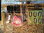
Did a quick plaque using a 60 degree vcarve bit. Much finer details than my 90 degree. Also tested out some masking paper and spray paint letters.
Sent from my iPad using Tapatalk HD
-
09-16-2013, 02:24 AM #39
Neuer Benutzer
- Join Date
- Jan 2013
- Posts
- 306
Spent some time squaring up the machine a little closer. Then machined a proper table top. Got my first taste of routing MDF again when I surfaced the top. What a dusty mess. Have my dust collector boot design completed so that will be cut next.
Ran into a couple issues tonight maybe someone can help.
1. Having problems with the alt units saving on the settings tab in Mach3.
I have the setup units on mm but work in inches.
Should the change on the settings tab stick each time I startup?
2. Tonight my touch probe script was acting crazy. It would touch off then make a move down. At that point it would move to the z height in the script plus the thickness of the probe.
I changed a setting in the general config to enable persistent DRO thinking it might help problem #1 above. Would this cause issues with the auto zero script?
Sent from my iPad using Tapatalk HD
-
09-16-2013, 11:09 AM #40
Member
- Join Date
- Apr 2007
- Posts
- 8082
When you change some of the settings you MUST save the settings manually. In the Config tab, at the bottom of the list, Save Settings is where you do it. Get in the habit of always saving any changes there.
CarveOne
http://www.carveonecncwoodcraft.com

 Reply With Quote
Similar Threads
-
Anybody know what happened to Steve Seebold?
By toothandnail in forum Tormach Personal CNC MillReplies: 6Last Post: 04-03-2013, 02:57 AM -
Anyone buy a Steve Simpson 4th Axis?
By WOTDesigns in forum Benchtop MachinesReplies: 12Last Post: 12-12-2012, 09:35 PM -
steve pen
By steve pen in forum MilltronicsReplies: 8Last Post: 11-10-2012, 03:15 PM -
Steve Timmons
By TheBigJW in forum Complaints and Praise DiscussionsReplies: 2Last Post: 08-07-2012, 03:08 AM -
Steve's design for a Breakout Box
By Steve-Tee in forum CNC Machine Related ElectronicsReplies: 0Last Post: 01-04-2008, 06:07 AM
