


For my next CNC I was thinking to incorporate a vacuum table. It will be a small table, approx. 36"x50" and perhaps a vacuum table its overkill but I would like to try it out for the experience
Do these systems come in smaller size or are all geared up for larger tables?
Has anyone installed one in a small table?
Any recommendations?
Thread: Vac System
Results 1 to 20 of 91
-
07-27-2013, 07:06 PM #1
 Member
- Join Date
- May 2009
- Posts
- 1332
Vac System
Nicolas
-
07-27-2013, 10:47 PM #2
Community Moderator
- Join Date
- Mar 2003
- Posts
- 35538
Are you talking about vacuum hold down? You'll typically need to make your own, or spend a lot of money to buy one. Also, there are different types, with different performance levels, and different applications.
Gerry
UCCNC 2017 Screenset
http://www.thecncwoodworker.com/2017.html
Mach3 2010 Screenset
http://www.thecncwoodworker.com/2010.html
JointCAM - CNC Dovetails & Box Joints
http://www.g-forcecnc.com/jointcam.html
(Note: The opinions expressed in this post are my own and are not necessarily those of CNCzone and its management)
-
07-28-2013, 12:08 AM #3
Member
- Join Date
- May 2009
- Posts
- 1332
Yes Gerry, vacuum hold down
Found a lot of sites for commercial use but haven't found yet anything for a DIY. Do you know such a site?Nicolas
-
07-28-2013, 05:04 AM #4
Registered
- Join Date
- Jan 2012
- Posts
- 394
I'll be using these.
ShopBot Motors
Read the write ups at the bottom of the page.
-
07-28-2013, 01:53 PM #5
Member
- Join Date
- May 2009
- Posts
- 1332
Great source on motors, thanks Falcon69
Any info on designing the table top and any other accessories required for a functioning system?Nicolas
-
07-28-2013, 02:07 PM #6
Community Moderator
- Join Date
- Mar 2003
- Posts
- 35538
As he said, read through all the threads on the ShopBot forum linked from that page.
Those motors are typically used for pulling vacuum through an MDF spoilboard, and work well for holding full sheets (or full table size sheets). They may not work for smaller single parts. If running single parts, you can add scrap material around the part to help hold it in place. Note that these can be fairly loud.
If you plan on mostly holding single parts down, you might be better off with a pod type system, like the vacuum clamps here:Vacuum Clamping (Vacuum Hold-Down Jig)
I plan on using a combination of both of these systems on my next machine.Gerry
UCCNC 2017 Screenset
http://www.thecncwoodworker.com/2017.html
Mach3 2010 Screenset
http://www.thecncwoodworker.com/2010.html
JointCAM - CNC Dovetails & Box Joints
http://www.g-forcecnc.com/jointcam.html
(Note: The opinions expressed in this post are my own and are not necessarily those of CNCzone and its management)
-
07-28-2013, 06:36 PM #7
Member
- Join Date
- May 2009
- Posts
- 1332
You are right Gerry, searching thru this site I found some really good info on vac systems; the best so far is the same site you mentioned (Joe Woodworker)
Having no experience on any vac holding system it looks like the Podz system is pretty simple and good
The same site has good info to build a simple vac pump but right now I don’t know which one I will although the Project V2 (Venturi Based Model) looks very interesting
But for starters I will have to find out what my requirements are in CFM / "Hg. Do you have a handy formula?Nicolas
-
07-28-2013, 10:20 PM #8
Community Moderator
- Join Date
- Mar 2003
- Posts
- 35538
For the Podz, CFM would depend on the porosity of the material you're trying to hold. For plastics, or sealed would, CFM would be near zero. I wouldn't really worry about CFM.
You always want as many in/Hg as possible. The higher the in/Hg, the stronger the hold.
I have my own custom version of the Venturi system that I use for veneering, and I also have an electric pump. I haven't used either with my CNC, but I'd prefer the electric pump, as long program runs could result in your compressor running a lot, especially if the material is porous.Gerry
UCCNC 2017 Screenset
http://www.thecncwoodworker.com/2017.html
Mach3 2010 Screenset
http://www.thecncwoodworker.com/2010.html
JointCAM - CNC Dovetails & Box Joints
http://www.g-forcecnc.com/jointcam.html
(Note: The opinions expressed in this post are my own and are not necessarily those of CNCzone and its management)
-
08-01-2013, 01:59 PM #9
Member
- Join Date
- May 2009
- Posts
- 1332
Still searching for info on my vac table top and pretty soon I will make a sample to try out some ideas I have but I was wondering..
Say the table top will have a bunch of 1/8" or 1/4" holes for the vac suction and even if I plug the unused holes perhaps the force of vacuum will still get some dust into the vac system and eventually I will either have to clean the vac system or worst it may get plugged.
How do you prevent you vac system from getting plugged?Nicolas
-
08-01-2013, 04:43 PM #10
Community Moderator
- Join Date
- Mar 2003
- Posts
- 35538
Say the table top will have a bunch of 1/8" or 1/4" holes for the vac suction......................................
How do you prevent you vac system from getting plugged?
I wouldn't use a system drawing vacuum through a lot of small holes, as they typically don't work very well.
Higher end systems use filters and or cleanouts to avoid clogging issues.Gerry
UCCNC 2017 Screenset
http://www.thecncwoodworker.com/2017.html
Mach3 2010 Screenset
http://www.thecncwoodworker.com/2010.html
JointCAM - CNC Dovetails & Box Joints
http://www.g-forcecnc.com/jointcam.html
(Note: The opinions expressed in this post are my own and are not necessarily those of CNCzone and its management)
-
08-01-2013, 07:31 PM #11
Member
- Join Date
- May 2009
- Posts
- 1332
I was planning to divide my table top into 3 zones with each zone controlled by a ball shut-off valve; so the center zone will probably be the most used one and the other 2 zones will be off with their holes being plugged. But right now I'm also considering the Podz system Originally Posted by ger21

I gather the electric pump you have Gerry is a vacuum pump? How much these pumps cost down there?
In my area they are around $500 + taxes, valves, gauge etc.
Do you know any place to buy used ones?Nicolas
-
08-01-2013, 07:49 PM #12
Registered
- Join Date
- Jan 2012
- Posts
- 394
If you use a spoilboard, like 1/2" MDF, the dust getting into the vac system isn't much of a problem. Do you still need to protect against it? Yes, but typically as long as that spoilboard is used and only occasionally removed and replaced, you won't need to worry about the holes getting crap in them.
At a job i used to work at, we had an aluminum table that had clean-outs in it and routered slots where the sealing gasket would be placed. Then the 1/2" MDF on top of that. I think we were running a 40 or 60 HP vacuum pump, damn loud thing too.
We would put on a sheet of 1/2" MDF, and would just keep surfacing it till it was like 1/4" thick, then replace it. It kinda sucked sometimes. Because of the coating they put on the surface of the MDF, and the fact the vacuum pump would suck moisture from the MDF, when we surface off that initial coat off the top of the MDF, it would look like we were making a boat when we cut the vacuum off. That MDF would warp so bad.
-
08-01-2013, 09:11 PM #13
Member
- Join Date
- Sep 2012
- Posts
- 1195
Normally, there is a filter on the intake of the vacuum pump. In an ideal world, there should be very little air movement through your vacuum system. If you have air moving, you aren't achieving a vacuum deep enough to be useful. You could think of it like a shop-vac. If you have the hose open, it moves are into the vac bringing debris with it. If you seal the hose to a surface, it can lift the object that it is sealed to. Why? because you have eliminated the air movement into the system and it is now achieving a deeper level of vacuum. In order for something to be at a state of vacuum, there must be no air present.
I'll see if I can get a diagram of the system up for you to see. I've already got a CAD drawing of the vacuum table, which I can quickly modify to the size you are thinking of. This will give you an idea of how vacuum tables are generally used. The design I have can be zoned from beneath, and it can also be plugged at each opening on the table and roped off with gasket to allow for pods or fixture boards to be attached.
For a table the size you are thinking, you will need around a 3-5hp vacuum pump, and it can't be a generously rated pump. If it's a 3hp pump, it will need to be able to draw 12 full amps of current without overheating. I think a 5hp pump would be a better bet. My table is about the same surface area right now and 5hp is just about right.
-
08-01-2013, 10:30 PM #14
Member
- Join Date
- May 2009
- Posts
- 1332
I understand the principle mmoe I was just wondering if I'm missing something since I never used a similar system. My idea regarding zoning is also similar to yours.
Regarding the pump, I have a hard time to find one locally to compare my cost with the system suggested by Gerry in post #6
It will be very interesting to see your drawing when you get some timeNicolas
-
08-02-2013, 03:47 AM #15
Member
- Join Date
- Sep 2012
- Posts
- 1195
Here's the first two basic drawings. The first drawing is the table surface itself (which I modified to about the table dimensions you specified (900mmx1300mm approx.) and the second is the Pod design I'm going to use. The grid is comprised of 1"x1" squares with 1/4" slots surrounding them. The slots are 4mm deep, leaving a little bit of gasket proud of the surface which allows it to seal. The rope gasket you need to use is very squishy, similar in structure to the closed cell foam insulation that you put around pipes. It needs to be able to compress easily so that it can seal to somewhat uneven surfaces.
The holes are 10.8mm, which is approximately the clearance size of an M12 bolt. The nicer table I've owned had a similar design, which allows you to plug the vacuum within the zones. If your table is zoned off to where only the first third of the table is open, you can then further close off unneeded ports so that only the locations of vacuum pods are open. It takes a bit of setup to put all those bolts in (10-20 minutes if you do most of them), but if you plan to use a set up for a while it's the way to go. Another option is cutting a piece of melamine around your pod locations, then sealing the melamine to the table with rope gasket. It takes about the same amount of effort either way, however, if you plan to need the same setup more than once, the melamine solution saves a ton of time every time you need that setup again in the future. Of course, these are production concerns, so if you don't do production work than it won't be worth it.
A quick way to create a custom hold down is also to place a 3/4 inch MDF core melamine panel over the entire table (this will seal it perfectly since the melamine is totally non-porous), then cut gasket channels about 1/16 inch inside of the edge of your parts with a small waffle inside the roped boundary. If there is not waffle, there won't be as much vacuum volume holding the parts and it can slip more easily. I've done this to do production runs of parts that are extremely difficult to hold otherwise and previously could only be cut with tabs.
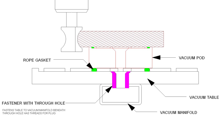
On the bottom of the table, you would have to come up with your own plumbing scheme. In some cases, you can use something along the lines of a 1" threaded fastener to go through the table and thread into some square steel tubing below, which is also sealed with a high quality silicone sealant to prevent leaks. The 1" fastener would then have to have the M12 threaded hole through it, allowing the air to go through. I've done it that way and it works fantastic, but the issue is that you need to be able to make those fasteners or be willing to pay someone to do so. There are many other ways to attach the vacuum plumbing the table, so I'll leave that part up to your own thoughts.
Usually, tables like this are made out of aluminum, phenolic, or high density plastics. None of which are inexpensive. I think no matter which you choose, you end up at around $400-600 worth of material for a 36x50 table. As I've drawn it, the table is 3/4" thick, but keep in mind that how you design the machine will determine just how rigid you need the table to be. Also, if you plan to attach any sort of jigs or workboards to it, you may again want to have it as rigid as possible. The 4mm grooves over the surface effectively reduce the thickness to about 5/8 as drawn, so it's not as thick as you'd think initially. I think the drawings are pretty self explanatory, but if you have questions feel free to ask.
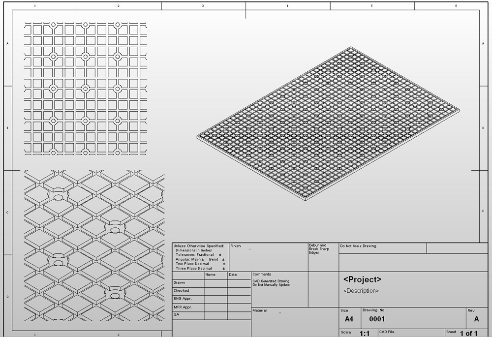
One thing not shown is the location of holes for holding the table down to the machine. I haven't really decided on that yet for myself, so they are TBD as far as my drawings go. Generally, I was planning to put them in the middle of one of some of the 1"x1" squares, countersunk but with plenty of meat left around the screw head before the edge of the 1"x1" perimeter.
-
08-02-2013, 06:36 AM #16
Member
- Join Date
- May 2009
- Posts
- 1332
Thanks for your time mmoe
Got to understand your drawings and since its kind of late here I will do it tomorrow
I'm sure I will have some questionsNicolas
-
08-02-2013, 09:00 AM #17
Member
- Join Date
- Sep 2012
- Posts
- 1195
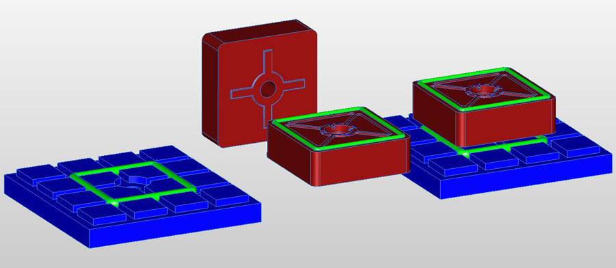
Here's a closeup of the top of the pod. The green in all the drawings represents the rope gasket. In the second image of my previous post, the assembly to the right shows the pod hovering above the gasket. The crosshair shape on the bottom is to index the base of the pod to the table grid and the center hole of the pod brings the vacuum up to the top of the pod where it is distributed to each vacuum chamber within the rope gasket.
I'll be machining some prototypes over the next few days, so I'll be able to post some photos of the actual parts at some point as well. That's really the best thing about a CNC machine, that it can make it's own parts.

-
08-02-2013, 01:22 PM #18
Member
- Join Date
- May 2009
- Posts
- 1332
Much appreciate your time mmoe, I have seen similar table waffle designs on the web but I also have seen designs similar to the one shown on this video
https://www.youtube.com/watch?v=fOrkvPF0pro
With the limited experience I have on vac tables I cant say which one is better but I prefer the one from the video because looks simpler and more practical. In my case I will modify the video design to include 3 zones and the spoilboard at the top I would not glue it but rather bolt it down to the vac box and therefore it will be easier to replace
Perhaps I misunderstand your drawings but the waffle design will be more time consuming to replace after it's damaged. Please let me know your opinion.Nicolas
-
08-02-2013, 08:33 PM #19
Member
- Join Date
- Sep 2012
- Posts
- 1195
The Donke video shows a table that I can't imagine would work for holding parts during routing. Their application is using their drag knife, not routing. I suspect that for the times that he does use it for routing, he does not cut through the material and leaves what is called an onionskin. With an onionskin, you then have to break the part out of the main board and it somewhat defeats the purpose of a vacuum table. If he does cut through the parts, I have no idea how he does because the moment you cut through your material you would end up with a giant vacuum leak into one of the holes. After making a 2 foot long cut with even a 1/4 inch bit, I would think there would not be any vacuum left to hold the part unless you were fortunate enough not to hit any of the holes in the table.
Commercially, which I think is where you get the best measure of what does or doesn't work, waffle style tables are the norm for a reason. First, you would never, ever cut into the table unless you made a catastrophic programming mistake. Just like the Donke video, you skin the table with a sheet of MDF so that you don't cut into the table itself. Unlike the Donke video, you don't drill holes through this MDF. The reason people use MDF for the table surface is that it is porous. The vacuum will travel right through the MDF, but only if you have a deep level of vacuum (minimum of around 18 in/mercury and best if closer to 24 in/mercury). The MDF skin seals to the rope gasket at the edges, and if you have zoned your table off then you would run a rope gasket between the zones to allow only part of the table to be used. You shave down the MDF, usually with a 2-3 inch diameter bit, by about the same .010" (or less) as suggested in the video. However, I think you'd find it very optimistic to expect the MDF to last 2 years unless you are also using a drag knife. With a router, you would cut through the parts material by about .005" or less, which will leave a shallow cut into the surface of the MDF. If you cut the same parts over and over, you could leave it and not resurface it. If you cut a lot of different parts, eventually those shallow cuts will start to add up and the material won't hold down because of the small amount of vacuum leak they provide under the part (like a channel for air to travel through under the part to the edge of the part). That's when it's time to resurface.
Vacuum is just one of those things where the logic behind it is not always immediately grasped. The air movement through the MDF will seem negligible. You would barely be able to feel that it is even there. However, the differential in pressure between the air above the surface of the MDF and the air within the MDF is so great that the parts are held down by the weight of the atmosphere, not the movement of air. I have a large 5 hp vacuum pump that is capable of moving the same amount of air as (guessing) 20 of those shopvacs. With a 1/4 inch hole (such as each of those in his table) exposed, the vacuum would drop by as much as 25% and I think parts would be in danger of starting to slip. If there was a 1 inch diameter hole exposed where vacuum could leak, the level of vacuum would drop to nearly nothing and parts would not hold down at all. The waffle pattern also is part of what makes the system work. In order to hold the parts down, you need reasonably even vacuum beneath the parts, the waffle pattern distributes the vacuum in a way that is very uniform beneath the MDF. I've designed mine to have 1"x1" squares with channels between, but it would be even better in terms of vacuum to go down to perhaps 3/4" squares because you would end up with less space between vacuum channels, and even more uniform vacuum across the table as the vacuum would kind of overlap across the tops of the squares within the MDF. I arrived at 1" squares as about the maximum because the amount of vacuum being pulled through at 3/4 inch is negligible, and the amount at 1/2inch is starting to be fair. The lead me to think that the maximum radius from a vacuum chamber should be about 1/2inch or there would be significant areas of the MDF surface that aren't really getting any vacuum beneath the surface. Bringing that radius from each side allows for a 1 inch gap between vacuum chambers.
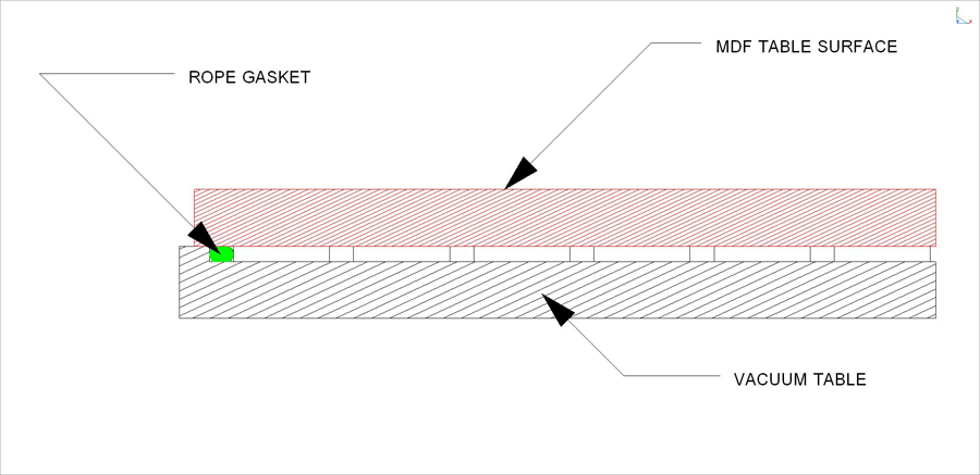
Here is a cross section view of what a standard vacuum table looks like:
If you are using pods, the pods are going to seal directly to the part face, but the pods is placed so that you don't run into it with the router bit. The point of using pods and having the ability to use pods, is that you can run profiling operations that can't be done with the part directly on a surface. You can also hold narrow parts that don't have a lot of surface area or parts that maybe aren't totally flat (lumber instead of sheet goods). Here's a diagram of what a pod system is typically used for:
-
08-02-2013, 08:43 PM #20
Member
- Join Date
- Sep 2012
- Posts
- 1195
Here's a video of the basic concept of an MDF table surface over a waffle style vacuum table. table in the video would not offer much for vacuum pod use due to the limited locations of vacuum ports coming through the surface, but it's otherwise pretty similar in concept.
Laguna CNC Vacuum Table Setup - YouTube
I have no idea why someone using such an expensive machine would be surfacing the table with such a tiny bit. a 3 inch flycutter would be much faster. Also, I've never had to flycut both sides of the MDF. It will pull vacuum through it either way if the system is sealed well. I don't know anyone operating these machines professionally who does that either, so as normal for youtube you can take the information they present as not entirely the gospel.
I do machine the board and flip it if it starts to warp. Usually this happens after a few weeks of use or if you don't cover the MDF with something when not in use. I lay trashbags over the surface to keep it from warping when it's not in use and that works well for me. If the MDF warps, it usually bows up at the edges making it hard to seal to the gaskets. Flipping it over usually solves that problem and extends the life of the spoilboard. I usually get a month or two out of each board doing light to moderate amount of work on them. It mostly depends on how different each sheet is cut which determines how often you have to resurface it.

 Reply With Quote
Similar Threads
-
Gecko G540 Bare Bones System (Enclosure, 48v 8.3a Power Supply, Cooling System)
By storm2313 in forum For Sale OnlyReplies: 0Last Post: 01-19-2014, 02:18 PM -
Gecko G540 Bare Bones System (Enclosure, 48v 8.3a Power Supply, Cooling System)
By storm2313 in forum For Sale OnlyReplies: 0Last Post: 01-06-2014, 11:15 PM -
Mitsubishi system Meldas 60/60s how to set G54/G55 tools coordinator system
By reg613 in forum Mitsubishi controlsReplies: 0Last Post: 07-26-2013, 08:38 AM -
Converting DSP controller system to Mach based system.
By Marwell in forum Machines running Mach SoftwareReplies: 0Last Post: 12-20-2008, 12:00 AM
