


I am getting into 3D modeling for scale models for Architecture. I am a 3D artist traditionally modeling in polygon meshes with little experience with Nurbs. I read that some cnc software accepts stl meshes. How common is this? I worked on a job recently where they could not use the mesh for CNC. I did not get a reason. I understand the meshes need to high poly counts to remove any unwanted faceting without any smoothing. Do I need to try to learn nurbs modeling or is my client not using a good CNC company?
The work I am doing is usually high concepts of organic shaped buildings. Very sculptural.
Thanks!
Results 1 to 20 of 34
Hybrid View
-
08-02-2013, 03:58 PM #1
 Registered
- Join Date
- Aug 2013
- Posts
- 17
Complex shapes for CNC. Can this be done in polygonal meshes?
-
08-03-2013, 04:50 AM #2
Member
- Join Date
- Sep 2012
- Posts
- 1195
Working in solids is easier to deal with than working in meshes, at least that's my experience. Both can be used, it just depends a bit on what software the CNC operator/programmer has available. I would recommend learning how to work with nurbs based software anyways, as it will only build on the skills you have. Not really a down-side to that.
I don't work in STL format often and haven't for years, but I think you could also bring your meshes into Rhino and create a solid from them, which could then be exported as a nurbs file.
-
08-03-2013, 01:23 PM #3
Community Moderator
- Join Date
- Mar 2003
- Posts
- 35538
There are several 3D CAM packages that are inexpensive, easy to use, and deal exclusively with mesh models. MeshCAM and DeskProto are two very popular ones.
The main benefit of using solid models is that higher end CAM packages can detect features of the models, and use more efficient toolpath strategies. Most mesh CAM programs only use a rater toolpath strategy, which can take a long time to produce smooth surface with out toolmarks, as they need to make many passes with a small stepover.
I would think that for organic type models, most of the advantages for solid models do not apply. I'd look for another company for your parts.
Any pics of what type of parts your talking about? Without seeing exactly what you're trying to do, it's hard to give an accurate answer.Gerry
UCCNC 2017 Screenset
http://www.thecncwoodworker.com/2017.html
Mach3 2010 Screenset
http://www.thecncwoodworker.com/2010.html
JointCAM - CNC Dovetails & Box Joints
http://www.g-forcecnc.com/jointcam.html
(Note: The opinions expressed in this post are my own and are not necessarily those of CNCzone and its management)
-
08-11-2013, 06:25 PM #4
Registered
- Join Date
- Aug 2013
- Posts
- 17
...
-
08-11-2013, 07:15 PM #5
Registered
- Join Date
- Aug 2013
- Posts
- 17
Thanks it is good to know its possible. See here for what I typically work on.

This is the rough mesh I started with (based off a laser scan) and retopo'd it to be water tight so the mesh is not messy. I am usually 3D printing scale models of buildings for a client but I have been asked about CNC. Would this be doable?
-
08-12-2013, 03:44 AM #6
Member
- Join Date
- Sep 2012
- Posts
- 1195
The biggest issue is simply the CAM software. This is the software that takes your model and generates a toolpath the machine can cut to produce the part. It would be possible provided that the person you use for CNC has CAM software that reads STL files. Most do, but I'm sure some don't. In some CAM software, I think you have to draw a surface beneath the mesh in order for that software to recognize it as a surface that can be machined (not everyone knows that trick). In others, it would automatically be recognized as a machinable surface. So the answer is yes, you can machine it and should be able to expect to machine it, but it will always come down to who you are working with, what CAM software they are using, and how well they know and understand their CAM software which generates the tool path. There is nothing about your product that is too difficult to produce, it's a matter of finding the right person with the right software to cut the parts.
The same is true of other file types, such as Rhino (.3dm) or ACIS (.SAT). Not every CAM package will import these formats, even though they are commonly used. Even if they do import them, they often are imported poorly because they aren't translated well (I notice this problem with .SAT files and version 4 or newer .3dm files in Bobcad-CAM). Other commonly used formats would be .3ds, DXF, DWG, and IGES. My personal preference is typically .IGES if I don't know what software is generating the file since I've found .IGES files to be less of a problem during translation and they almost always import correctly. But that is just what works best with Bobcad-CAM, which is what I own, so if someone else owns software that won't import and .IGES file, then they obviously won't like that format. I could also cut your file directly from an STL with Bobcad-CAM, if you were local.
If you would like to see what a tool path looks like and how a mesh is translated into a tool path, feel free to post a small sample section of your mesh and I'll run it through my CAM software to show you what has to happen to cut it out.
-
08-12-2013, 04:15 AM #7
Community Moderator
- Join Date
- Mar 2003
- Posts
- 35538
MeshCAM is $250, incredibly easy to use, and would work fine for those types of parts. Just load the model, pick your tool and stepover amount, and click a button. Depending on the polygon count, tool size, and PC power, you'll see a toolpath in anywhere from 10 seconds to 10 minutes. Typically less than a minute with a modern PC. The only issue may be if the parts are large. Since .stl files are made up of triangles, large models can eat up huge amounts of memory.Not every CAM package will import these formats, even though they are commonly used. Even if they do import them, they often are imported poorly because they aren't translated well
As for import quality, the .stl format is much simpler than many others, and I wouldn't expect to see any issues with using them.
On issue with a model like that is the level of detail. To get that much detail, you may need to use a pretty small tool to get the detail you want. The smaller the tool, the longer it'll take to cut. The longer it takes to cut, the more it will cost.Gerry
UCCNC 2017 Screenset
http://www.thecncwoodworker.com/2017.html
Mach3 2010 Screenset
http://www.thecncwoodworker.com/2010.html
JointCAM - CNC Dovetails & Box Joints
http://www.g-forcecnc.com/jointcam.html
(Note: The opinions expressed in this post are my own and are not necessarily those of CNCzone and its management)
-
08-12-2013, 05:18 AM #8
Member
- Join Date
- Sep 2012
- Posts
- 1195
Just to clarify, I was speaking specifically about ACIS and Rhino files in terms of compatibility. I agree that STL files almost always open fine in software that can read them, and when they don't it is usually because the file was not well crafted.
I've worked with meshes that cover an entire 1200x1200mm surface with high levels of detail which were generated from point clouds. When they get that big, the processing time to generate a tool path with a .5mm step over is 4 hours or so (plus or minus 2 or 3 hours ), and I have a very fast computer. Like Gerry says, the file sizes get huge. Once you have a tool path, the maximum speed you can cut something 3d like that is typically around 3500mm/min. My machine will rapid at 20,000mm/min and cut at up to 15,000mm/min, but 3500mm/min is the fastest it can do these jobs. Any faster and I start getting concerned about the wear and tear on the machine (it will go faster, but it sure starts to sound very bad for the machine). With that in mind, in one hour you can only cut about 75mm wide, making the total run time fall around 16 hours for a 1200mm x 1200mm part. If you can live with half the detail (double the step-over) you can do it in 8 hours of cutting and the tool path generation takes closer to 1 hour (not sure why it's 4 times longer for double the resolution, but it just has been for me).
As Gerry points out, the more detail you want, the more it would cost and I'm sure you can see that from the run times listed above. I'm not sure what the average rate is where you are located, but I charge upwards of $100/hr depending on the job for machining time and $50/hr for setup time (programming, fixtures, bits, etc.), so a job like the one I described would be between $1000 and $2000.
Lately, I've been testing lots of different meshes which are being generated from point clouds and the end products are in that 1200x1200x120mm size, often needing multiple panels assembled together into larger end products. Many of the programs are made up of 10's of millions of lines of code, and that only covers portions of the total job. So far, machining the point clouds directly is working out better than the meshes and the slight missing offset for the tool size is not a factor for these parts. Large meshes are just really, really hard to work with, but the same is true of large surfaces with similar detail levels.
-
08-14-2013, 05:56 PM #9
Registered
- Join Date
- Aug 2013
- Posts
- 17
Thanks all good to know. I did not realize you can machine pointclouds directly if needed. I may send a sample mesh that I generated so you can let me know if it is usable.
-
09-02-2013, 06:16 AM #10
Member
- Join Date
- Sep 2012
- Posts
- 1195
You can machine point clouds directly, but through further experimenting over the last couple weeks I've found a way to get a mesh that is machining just as well as the point cloud, but with the advantage of an offset for the tool geometry. It sounds like you have an STL to start with, so you probably don't really need to convert form point clouds. However, if you do need a mesh from a point cloud, the best meshes I've been able to produce are done with software called Cloud Compare, which is a freeware/shareware program. It will open a point cloud, then generate a mesh from it by connecting the dots directly into triangles from point to point, so no smoothing or noise reduction which usually results in lost detail. You can then export the mesh as an STL which can be machined.
While Bobcad, which is what I usually use, will open an STL and generate a tool path from it, I've found that the software Gerry recommended (Meshcam) is much faster at generating the type of toolpath you're looking for from a mesh since it is able to use more of the computers resources due to it's software architecture. I would also recommend Meshcam after doing quite a lot of direct comparisons for any mesh related work. Also, I find that if you save the files as a Binary STL, it's generally more compatible with most CAM software, where ASCII files are less supported (though Meshcam works with both). The Binary STLs are also smaller in file size (about 1/4 the size), so easier to handle through downloads or emails. As a matter of best practices, I'd stick to sending STLs in Binary format when working with CNC providers.
Feel free to post a mesh and I'll show you a tool path from it.
-
09-11-2013, 01:48 AM #11
Registered
- Join Date
- Aug 2013
- Posts
- 17
Thanks. If you want to check out the mesh here a 1/4 of the model.
Facade_Binary.zip (138.0 MB)
https://mega.co.nz/#!Ik5AVISY!GZIc1U...__v5NvzaO_8AX4
-
10-11-2013, 09:28 PM #12
Member
- Join Date
- Sep 2012
- Posts
- 1195
I tried downloading the file, but for whatever reason it just won't let me do it. I don't think the site is bad, but it behaves in a sketchy way that makes me nervous about letting it do everything it seems to be trying to do. Not sure why it won't just let me use the downloader in my browser and I'm always nervous about sites that don't.
-
10-13-2013, 12:46 AM #13
Registered
- Join Date
- Aug 2013
- Posts
- 17
Its my first time using this site. As far as I know the website is legit. I will send a different link when I am back on my computer.
-
10-15-2013, 03:24 AM #14
Registered
- Join Date
- Aug 2013
- Posts
- 17
Try this instead. http://we.tl/WPRDwo5vfx
The link will delete after 7 days automatically
-
10-23-2013, 02:41 AM #15
Member
- Join Date
- Sep 2012
- Posts
- 1195
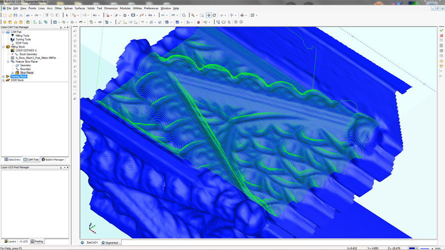
Here's a quick image showing some toolpaths on a small portion of your file. Just to speed up the process, I cropped out a small section of the mesh and ran a Planar Slice toolpath on it. This was done in Bobcad V24, but if I were hired to do this job I'd probably just buy Meshcam, which performs quite a lot faster. I'll probably be buying Meshcam just for these kinds of jobs at the end of the year (budget is always tight until then!). Also, keen eyes with knowledge of toolpaths might notice that the offset from the surface is larger than the tool radius. I did this just to make the toolpath a little more clear by leaving an allowance.
-
10-23-2013, 03:52 AM #16
Ghost
- Join Date
- Dec 2008
- Posts
- 4548
There are settings you can make that will make the toolpath calc "a flash"..................fyi. Originally Posted by mmoe

-
10-23-2013, 04:19 AM #17
Member
- Join Date
- Sep 2012
- Posts
- 1195
Hey BurrMan,
Don't know if you downloaded the full res file before it disappeared from the link, but I can barely get the model to load in V25 or V26. I think my video card has been giving me some trouble ever since updating the NVIDIA drivers in September but it's not enough of a difference that I think it would be the difference between success or failure. While I've invested in Bobcad and probably will continue to do so for a full featured CAM system, in this case I think Meshcam is just the right tool for the job and will pay for itself quickly in time saved. In side by side comparisons where I can get Bobcad to work with these large STLs, Meshcam simply wipes the floor with Bobcad (usually about 6 times faster with comparable tolerance settings and step overs). More often than not, Bobcad crashes before generating code and you start over. I haven't had a crash with Meshcam on these files yet and it's really, really cool to see 8 cores humming along at 100% for 4 hours straight. I can't think of a single piece of software out there that is that well optimized for multicore hyperthreading. In talking to the developer in the Meshcam forum, he said that it was a point of emphasis when he wrote the software. There are some periods where it only uses about 25% of the system (particularly at the start of a Planar Slice calc), but then it kicks into high gear for the bulk of the calcs.
-
10-23-2013, 09:49 PM #18
Ghost
- Join Date
- Dec 2008
- Posts
- 4548
Hey mmoe,
Dont get me wrong about the other softwares. CamBam and MeshCam are very cool programs and also very good at work with stls.
I understand what you see with the BobCad and large stl's that you refer to with regard to loading them, viewport manipulation, and toolpathing.
But just wanted to point out that you can make some settings when you need to work with these, that will change that behaviour. It would be a combo of your "viewport mesh angle" to allow the large stl to "rotate/move fast",
and also for the toolpath calc, the machine tolerance dropped. With BobCad, you can get that "4 hour toolpath" in the minutes and seconds too, but there will be some point, where the calc gets long. The computer will then determine the success of that.
Getting CamBam and MeshCam as an added tool for you, would be cool. Like you said, they can eat the STL cuts for snack. I just didnt want you left with "My other one CANT".....
-
10-23-2013, 10:39 PM #19
Ghost
- Join Date
- Dec 2008
- Posts
- 4548
Hey mmoe,
Just downloaded the model your speaking of. It IS a very dense mesh and even the display settings change I was speaking of doesnt give usable performance.
However, to use large datasets like this, I would use BobArt and it's emboss from component command. If you have BobArt, this will give you the same thing you get from CamBam and the others.
If you have BobArt and want to see this, I can make you a video with that model.
Anyway, I dont want to turn this into a "my software thing". We can move it to the appropriate forum if you want to explore it a little....
Burr
-
10-23-2013, 02:44 AM #20
Member
- Join Date
- Sep 2012
- Posts
- 1195
I'm curious if this file originated from a point cloud? If so, what is your preferred software for meshing the point cloud?

 Reply With Quote
Similar Threads
-
polygonal hex turning on puma 240 ms
By tgjeep in forum Daewoo/DoosanReplies: 1Last Post: 05-11-2013, 12:32 PM -
Newb question -Why use meshes? confused
By Rich05 in forum Rhino 3DReplies: 4Last Post: 02-03-2009, 02:39 AM -
Polygonal turning
By sting007 in forum Daewoo/DoosanReplies: 1Last Post: 09-11-2008, 07:29 PM -
Really Big Calculator for Polygonal Coordinates
By Geof in forum Haas MillsReplies: 1Last Post: 05-12-2007, 06:49 PM -
Polygonal Turning
By ve2lva in forum Daewoo/DoosanReplies: 24Last Post: 10-20-2006, 10:21 PM
