


I now have the need for a fairly small, light mill to go in the garage section of a truck camper we are building. I don't have set limits on size and weight but I certainly can't take my 7000 pound Shizuoka bedmill with me when we sell the house and start our travels. I want to be able to still do some wood, plastic, and aluminum machining while camped out for weeks on BLM land or whever we may go. It may also be nice to be able to make parts for our truck camper as I am doing now with my cnc mill and lathe.
I want quality and have been spoiled by AC servomotors, ballscrews and box ways. I happen to have six Adept/NSK linear robot modules new in the box old stock. Five of them have 500mm travel and one has 300mm travel. They have 10mm pitch ground NSK ballscrews, 4 linear carriages on square rails, and 300 watt brushless servomotors. I have plenty of EN-204 Control Techniques drives which can drive 20 pounds attached to one of these modules at 1400 IPM, 200mS acceleration and a following error of less than 2.5um during travel and 10um on axis reversal.
Obviously I would like to use these modules as they would speed up construction of a small mill considerably. Since I only have one 300mm slide, I was thinking of using it for the Y axis. The travels would then be 500mm X, 300mm Y, and 500mm Z, or about 20 inches x 12 inches x 20 inches. Depth of throat always being a limitation on a classic XYZ mill, I don't see a reason to make Y more than 12 inches in travel. 20 inches in Z seems excessive, but those are the lengths I have on hand.
I have put together a quick CAD drawing of what the base xyz configuration might look like. I am considering making most of the Z support and the main baseplate out of 1 inch thick ground aluminum plate and the saddle plate connecting Y to X of 5/8 inch thick ground plate. In the pictures I have shown the mill at low Z and high Z limits (the blue slider) and the mill table at the ends of X and Y travels.
Do you think the 1 inch plate with the 1 inch thick triangle supports and 1 inch thick baseplate would be reasonable to support the Z axis? The brushless motor is enclosed in the top of the Z axis which makes it look taller in the drawing. The better mounting holes are on the other end from the z axis drive motor which is one reason why I have the motor end positioned at the top of the z axis on the mill. I brought the rear plate up high enough to enclose six of the 10 threaded mounting holes on the rear of the z-axis slide.
The last link is a youtube video I made years ago of these same slides in a gantry configuration. That design is not practical for our RV since I need more Z and clearance than a gantry will deliver. The video will give you an idea though what these slides are capable of. The allowable roll pitch and yaw figures referenced to the slider are around 400 pounds a foot from the slider....should be plenty beefy for this configuration.
cnc gantry test - YouTube
Results 1 to 16 of 16
-
08-05-2013, 03:31 PM #1
 Gold Member
- Join Date
- Dec 2005
- Posts
- 484
Basic simple bedmill build from mostly off the shelf parts
-
08-05-2013, 10:45 PM #2
Member
- Join Date
- Apr 2004
- Posts
- 5737
I've made a CNC router from slides like that; it works pretty well. Unless you really need that 20 inches of Z travel, though, I'd say make your X and Y axes from the 500mm units and use the 300 for the Z. You'll still need to provide gas springs or something to keep the Z axis from dropping when the power's turned off, but you will have a machine that's a lot more rigid. Since you have a lot of those 500mm units, you might consider using a pair to run the X axis - that would be a lot more stable than using one. I imagine you probably want to build a gantry machine to save space, so attaching each gantry leg to a separate actuator makes sense. If you've really got a roomy camper, I suppose a case could be made for a moving table machine, though.
What are you controlling this with - EMC?
Andrew Werby
www.computersculpture.com
-
08-06-2013, 01:08 AM #3
Gold Member
- Join Date
- Dec 2005
- Posts
- 484
Hi Andrew, thanks for the reply and tips.
All of the slides have a brake on the motor, so the slides are locked from movement when the power is off.
I don't think I need 20 inches of Z, but then again, I have used that much on my Shizuoka when boring a deep hole in a large object...
Making Y 20 inches means you really need a 20 inch throat from the z slide to the cutter. Even my giant cnc mill doesn't have that much throat...I think it is 16 inches.
We have the height for this in the camper...the garage pod will be 11 feet long by 8 feet wide by 8 feet high and I am dedicated the rear bench to the cnc mill and worktable space. The other part of the garage pod will hold motorcycles and sometimes snowmobiles (which will need to tuck in their skis under the cnc mill bench...should be ok).
Gantry with dual X slides would require quite a bit more work and machining, then you still don't get very much Z (maybe 8 inches or so).
I am controlling the mill with Kflop and maybe their motion software. Mach3 or EMC with parallel port can't generate the 450khz step rate I need with the 8000 count encoders on the brushless motors.
Just for fun, here is a model of what our truck camper will look like. It is on Isuzu 20 foot flatbed with about 11,000 pounds of payload. We are nearing completion of a custom flatbed camper (removeable) and then will build the garage pod.
-
08-06-2013, 10:32 PM #4
Member
- Join Date
- Apr 2004
- Posts
- 5737
Wow, that's going to be a heckuva camper! Is generator power clean enough to run CNC machines? Motors with brakes do save you the hassle of providing gas springs or counterbalancing. It sounds like you're pretty set on what you want, but I don't see why building a gantry mill would be harder than building a C-frame mill - it seems that making a rigid structure for that would be a lot more challenging, particularly if you're trying to save weight. Having more machining area is a good thing; with a gantry, you don't have a "throat". And if you do it right, you should be able to retain the full (12") travel of your Z axis slide, which would be sufficient for most things while minimizing the leverage working against your rigidity.
Andrew Werby
www.computersculpture.com
-
08-07-2013, 09:52 AM #5
Gold Member
- Join Date
- May 2005
- Posts
- 3920
You can't take that Shizuoka mill with you but you can use it to make a nice mill. Originally Posted by KTP

I know nothing about those specific slide assemblies but my option of most automation slides is that they are very stiff at all. I can't see them being used for a CNC machine without additional support.I want quality and have been spoiled by AC servomotors, ballscrews and box ways. I happen to have six Adept/NSK linear robot modules new in the box old stock. Five of them have 500mm travel and one has 300mm travel. They have 10mm pitch ground NSK ballscrews, 4 linear carriages on square rails, and 300 watt brushless servomotors. I have plenty of EN-204 Control Techniques drives which can drive 20 pounds attached to one of these modules at 1400 IPM, 200mS acceleration and a following error of less than 2.5um during travel and 10um on axis reversal.
Yes they wold but would you be happy with the results?Obviously I would like to use these modules as they would speed up construction of a small mill considerably.
300mm on the Y sounds good until you look at overhung loads. Those slide assemblies would have to be very strong to support a reasonable spindle 12" from the slide. I suspect you will have a hard to deal with mechanical strength problem.Since I only have one 300mm slide, I was thinking of using it for the Y axis. The travels would then be 500mm X, 300mm Y, and 500mm Z, or about 20 inches x 12 inches x 20 inches. Depth of throat always being a limitation on a classic XYZ mill, I don't see a reason to make Y more than 12 inches in travel. 20 inches in Z seems excessive, but those are the lengths I have on hand.
Seriously I'd reconsider especially knowing that you have a machine shop with a large mill already. I'd use that mill to build up your new one out of box sections. These could be steel tubing or aluminum castings. For mobile usage Aluminum would likely be better.I have put together a quick CAD drawing of what the base xyz configuration might look like. I am considering making most of the Z support and the main baseplate out of 1 inch thick ground aluminum plate and the saddle plate connecting Y to X of 5/8 inch thick ground plate. In the pictures I have shown the mill at low Z and high Z limits (the blue slider) and the mill table at the ends of X and Y travels.
I want to say no here, but hen the problem becomes what is reasonable. As you have in pictured there is nothing to support that aluminum plate after the gussets. Thus you effectively have a 1" thick hinge. You might think that is fine but many of the "X1", I beleive, sized mills suffer from their cast iron pivot. I'd strongly suggest a rethink is in order here. Yes reusing your slides sounds great but I'm not convinced they will give you the results you want.Do you think the 1 inch plate with the 1 inch thick triangle supports and 1 inch thick baseplate would be reasonable to support the Z axis? The brushless motor is enclosed in the top of the Z axis which makes it look taller in the drawing. The better mounting holes are on the other end from the z axis drive motor which is one reason why I have the motor end positioned at the top of the z axis on the mill. I brought the rear plate up high enough to enclose six of the 10 threaded mounting holes on the rear of the z-axis slide.
It isn't the slide alone that has to be beefy. As I noted I haven used that particular brand of automation slide but have to repeat it is the whole structure that makes and break a mills design. Given that you believe the slides themselves are good enough the obvious question is what abut the rest of the structure. To that end I really believe you need to consider stiffer cross sectional members. Maybe not though if the design is integrated into the bench more. Beyond that 400 pounds isn't a lot for a mill.The last link is a youtube video I made years ago of these same slides in a gantry configuration. That design is not practical for our RV since I need more Z and clearance than a gantry will deliver. The video will give you an idea though what these slides are capable of. The allowable roll pitch and yaw figures referenced to the slider are around 400 pounds a foot from the slider....should be plenty beefy for this configuration.
cnc gantry test - YouTube
Which brings up an interesting suggestion, in a usage situation like this why not go for a bench integrated solution instead if the more traditional mill sitting on a bench approach. It would help you keep things light ( relatively) while keeping the structure stiff. It might not be the solution for a home shop but this is a shop on wheels. With the machine designed right into the work bench you should be able to save on weight while providing for plenty of stiffness.
-
08-07-2013, 01:57 PM #6
Gold Member
- Join Date
- Dec 2005
- Posts
- 484
Excellent points wizard. I think the reason I want to go with the automation slides vs a ground up build using discrete ballscrews and linear bearings is so much of the work has been done for me in the slide, even if it is not exactly a perfect fit for a particular application. It is like using a microcontroller to do a task that could be done with 10 or 12 74 series logic chips....the microcontroller just gets you a faster solution that in most cases works just as well.
That being said, perhaps I should mount one of the 500mm travel slides to the table on my Shizuoka mill and make some deflection measurements at 12 inches from the slide using a dial indicator in the BT30 Shizuoka spindle. The NSK data sheet gives a allowable roll of 600N-m, which would be 440 foot-pounds. How much then would say 50 pounds of force deflect a rigid bar or plate mounted to the automation slide carriage? If I can subtract out the deflection of the bar itself, or use one so massive that the deflection is negligible, then I can get a idea of how much the 4 carriage slider mechanism will deflect when subject to a 12 inch overhang load. I could do this for roll pitch and yaw and get a very good idea of what the slides can handle, then design the structure that holds the slides in such a way that it does not add to this inherent deflection.
If the deflection measurement is less than 0.001", I am golden and would be comfortable using the slides. If it is more like 0.01" then we have problems.
-
08-07-2013, 04:28 PM #7
Gold Member
- Join Date
- May 2005
- Posts
- 3920
The problem with automation slide is the vast numbers available with a wide array of strength qualities. It is really hard to comment on those specific slides as I never used such. In general though they require stiff mounting surface to deliver rated loads. Originally Posted by KTP
By the way I wasn't suggesting to not use the slide assemblies just to look at a stiffer design to mount them on. For example if you want to build with aluminum plate consider building a box column for the "Z" and the base. Basically you want a design that will resist the full effort the servos will exert if something goes wrong. If the Z strokes down hard against something the frame needs to not bend and deform. Then you have the issue of vibration and dynamic deflection under normal machining loads.
By the way you have nice servos for this machine. With a bit of programming effort you should be able to set them up to fault before they do serious damage to the machine.
It is the whole ball of wax that counts. Even if the slides pass your stress test the frame they will be mounted to need to be able to support the slides properly. This is what I'm worried most about your design. Mind you, in part the suitability of your design depends upon how hard you intend to use the machine and how much vibration you can handle.That being said, perhaps I should mount one of the 500mm travel slides to the table on my Shizuoka mill and make some deflection measurements at 12 inches from the slide using a dial indicator in the BT30 Shizuoka spindle. The NSK data sheet gives a allowable roll of 600N-m, which would be 440 foot-pounds. How much then would say 50 pounds of force deflect a rigid bar or plate mounted to the automation slide carriage? If I can subtract out the deflection of the bar itself, or use one so massive that the deflection is negligible, then I can get a idea of how much the 4 carriage slider mechanism will deflect when subject to a 12 inch overhang load. I could do this for roll pitch and yaw and get a very good idea of what the slides can handle, then design the structure that holds the slides in such a way that it does not add to this inherent deflection.
If the deflection measurement is less than 0.001", I am golden and would be comfortable using the slides. If it is more like 0.01" then we have problems.
-
08-07-2013, 04:58 PM #8
Gold Member
- Join Date
- Dec 2005
- Posts
- 484
I understand what you are getting at.
I do think that determining the characteristics of the slides themselves will help a design. If the slides deflect 0.1" with a 20 pound load then it would not make a lot of sense to design the mounts to only deflect 0.0001"...wasted effort. Conversely if the slides only deflect 0.001" with a 20 pound load then it would be dumb to design mounts that deflect 0.1" under that same load.
I just mounted a slide to my Shizuoka table and attached a 1.5x1.5x14 inch bar of tool steel from the scrap bin to the slide hanging off the side. This setup only lets me measure forces out to about 10.75" max to the side from the centerline of the slide. I would think the deflection would be linear but then again, maybe not. The balls inside the carriages on the linear ways would be pressing into the races...the races are somehow fixed to the slide block which is bolted to the aluminum slide mechanism.
But anyway, here are some measurements I obtained with various weights and a dial indicator:
Deflection on the dial indicator of 0.001" for 12.16 pounds positioned 10 inches from the centerline (dial indicator measuring at the 10 inch point)
Deflection on the dial indicator of 0.001" for 9.47 pounds positioned 10.75 inches from the centerline (dial indicator measuring at the 10.75 inch point)
Pressing very hard on the bar at the 10.75 inch point I could get it to measure 0.005" on the dial indicator. I need to go make a few more measurements to get a better idea but it sounds a bit worse than I had imagined. How much would a X2 or X3 deflect on the Z axis if you positioned a mass 10 inches to the side of the z axis carriage?
-
08-07-2013, 06:05 PM #9
Gold Member
- Join Date
- Dec 2005
- Posts
- 484
Ok I realized I could use a different lever bar for placing weights than the measurement bar, as long as they were parallel to each other. This allowed me to take the measurements at the 10 inch point along the tool steel bar which has zero measureable deflection and use a much longer section of 8020 square extrusion as the lever arm where I can place weights very far out. I will attach a picture of the setup which might make more sense.
Ok, all of the measurements were done at 10 inches from the side of the centerline of the linear module slide measuring off of a square bar of tool steel clamped to the slide. The various weights were placed along the extrusion at different distances to get some different deflection data.
With 9.47 pounds positioned 30 inches from the centerline of the slide, I measured a deflection of 0.0020" on the dial indicator at 10 inches
With 9.47 pounds positioned at 20 inches from the centerline of the slide, I measured a deflection of 0.00148" on the dial indicator at 10 inches
With 15.12 pounds positioned at 30 inches from the centerline of the slide, I measured a deflection of 0.00375" on the dial indicator at 10 inches
The last data point being the largest mass, I calculate it was an equivalent weight of 45.36 pounds at the 10 inch measurement point. This caused the deflection of 0.00375". This would represent a "stiffness" of about 12,000 pounds per inch. From another thread, jsheerin mentioned that you want a stiffness "for steel 50k to >200k lb/in, for aluminum you'd want 20k to >50k, and for wood around 2.8k to 12k."
At 12k lb/in, I am at the upper end for wood but below the level for machining aluminum. This is at 10 inches from the centerline though, so if the distance from the cutter to the centerline of the slide were halved to five inches, then the stiffness at that point would be acceptable for a decent finish on aluminum parts.
All of this would assume that the rest of the setup did not add significantly to the deflection, which is a big assumption.
Do any of you have data figures of these type of tests on your benchtop mills for comparison?
-
08-07-2013, 11:28 PM #10
Gold Member
- Join Date
- Dec 2005
- Posts
- 484
Flawed setup! Before breaking down the test rig, I removed the plate and tool steel test bar from the linear slide and bolted the test bar directly to the ~800 pound table on the Shizuoka mill. I then did a deflection test to see if the bar+plate moved at all under a load. I was quite surprised to see very similar deflection of 0.001" with a 10 pound load as I did when it was bolted to the linear slide! I don't know right now if the 1.5 inch by 1.5 inch tool steel bar is deflecting or if the C-clamps holding the bar to the aluminum plate are deflecting.
This *may* mean the linear slide actually has much less deflection than I previously measured. I need to think of a way to attach a lever arm such that all of the deflection would be responsible from the linear slide and not the bar or mounting system for the bar.
Stay tuned.
Edit: With a different bar (2x2 square tube with 1/4" wall) still c-clamped to the aluminum plate I get a deflection of 0.0015 at 10 inches from the centerline of the slide with a applied force of 30.24 pounds. This puts me at a calculated stiffness of 20,000 pounds/inch which is still a bit low for aluminum (and not taking into account the rest of the machine which will have added deflections) but it does at least get me into the Taig/X2 range I am going to bet.
I don't know how I would design a Z axis even on a gantry that used these slides but had a smaller overhang than around 4 or 5 inches. This may be one of those times where you just go ahead and build the system and see how it cuts. Except for the few plates and gussets I need to fabricate, it wouldn't take long to knock together the simple xyz configuration and bolt on a Taig headstock (I happen to have one of those which is why I mention it)
-
08-08-2013, 03:52 PM #11
Gold Member
- Join Date
- Dec 2005
- Posts
- 484
This morning I changed out the test setup for a plate and section of bar that is actually bolted to the slide table instead of c-clamped to the plate. The problem must have been flex in the c-clamps because now I am measuring a deflection of less than 0.00025" with 15.24 pounds of force applied at 10 inches from the centerline of the slide. This translates into a stiffness of 60,000 pounds/inch which is well within the range for acceptable milling of aluminum. If all three axis had worst case 0.00025" deflection at 10 inches from the slide then the stiffness would still be in the 20,000 pounds/inch range (not sure exactly how they might add up but seems a reasonable guess). This is still acceptable for aluminum, especially with a small high speed cutter as the tables can move at many hundreds of inches per minute.
So having determined that the slides are decent for the amount of work (read zero) involved in setting up motors, ballscrews, linear ways and limit switches, I think the plan of attack is to come up with a configuration that gives the most rigidity for the largest travel in all three axis while keeping the overall weight down. I still think the classic c-frame xyz mill is probably the way to go. I am looking around at the few build threads that used linear bearings in a c-frame construction and note that they usually made a box or at least u shaped structure for the column. I have a big plate (36" x 24") of 6061 T651 1" thick aluminum that I would like to use for the base and column. I wouldn't have a problem with filling the column with epoxy granite if vibration dampening was still needed.
I am going to modify my drawing to extend the column higher to encompass 10 of the mounting bolts on the linear slide back, and instead of the forward triangle gussets, I am going to use 1 inch thick side plates to form a U-channel column supported all the way up. It is either this method or try a weldment of thick walled rectangular steel tube, but talk about heavy!
-
08-08-2013, 08:41 PM #12
Gold Member
- Join Date
- Dec 2005
- Posts
- 484
Taking some advice from you guys I reconfigured the drawing to have X and Y use the 500mm travel linear modules and Z use the 300mm travel module. This did have the advantage of making the Z axis seem more reasonable in height relative to the machine. I also moved the Z axis and column support up and over the Y slide such that there is 2 inches of clearance between the top of the tooling plate where the work would fasten and the bottom of the Z axis linear module. This gains you about 90mm in Y travel for relatively thin items like panels...things that tend to use up Y axis travel. Obviously the 2" wouldn't be good for a vice, but if you are using a vice, then you probably are not needing more than 6 or 8 inches in Y travel on that part. This seems like an excellent compromise between getting the most Y and maintaining high rigidity and a traditional xyz mill configuration.
As drawn, the (fake, representative) spindle center has 13.5 inches of clearance to the column the z axis is mounted and sticks out 10 inches from the z axis slide. I used this distance and number because those were deflection test results and give me a good idea of what a reasonable spindle distance might look like for machining aluminum. For an even stiffer configuration, perhaps removing a spacer block or something to reduce the distance to the z-axis while cutting those harder materials.
The rear columns are 1 inch plate...I plan to use 6061 T651 because I have a 2 foot by 3 foot piece. I do not know how I will tap the end holes in the blue part to enable it to be bolted to the baseplate. Even my Shizuoka doesn't have that type of boring capacity...hand drill? This is the case where I could use a knee mill with 40 inches of Z...
You can see in the last pic with the Z up at it's highest point and the X and Y moved back from Z that the Y travel of 20 inches is now not really useable. I can probably capture a good 14 to 16 inches of it with a reasonable spindle length but getting all 20 inches would require quite the long spindle spacer block. Perhaps I can one day trade a 500mm slide for a 400mm slide...but mine are unused new in the box so very attractive to use.
This feels very easy to build and doable...except for the blue column supports and their tapped holes on the bottom.
The mill would have rapids of over 1000IPM, resolution of 1.25um, precision NSK ground ballscrews, NSK rails and carriages, 300 watt brushless servos.
I have about $500 total in the slides...they were quite the steal which is why I bought so many. At some point I will have to sell the rest...or maybe build a 2nd machine and sell it...
-
08-09-2013, 01:59 AM #13
Gold Member
- Join Date
- Dec 2005
- Posts
- 484
Ok, a little more thought and refinement.
I decided to narrow the bottom baseplate such that the z axis column supports (shown in blue) would attach from the sides at all points. This eliminates the need to drill and tap a hole in the end of a > 20 inch length part. This does mean the baseplate needs tapped holes in it's sides, but being only 8 inches wide, this is easily doable on the Shizuoka (has a 20 inch Z travel).
I have also added a cutout in the column support where the adept servo motor power and encoder/limitswitch cables exit the module. It is a small cutout but I didn't want to remove too much material from such an important structural component. Should be able to painfully screw and unscrew the connectors, perhaps with help of soft pliers. All of the other axis modules have the end with the cables in the clear.
On the z axis column supports, I added a short rear plate near the bottom and two gussets? in between sets of bolts that attach the z axis linear module to the column. This should give some stiffening without blocking access to the module mounting screws. I know someone is going to say fill the z axis with epoxy granite, but the difficulty here would be all of the (12 of them) bolts that attach the z axis module to the plate. You would have to create 12 deep channels that the epoxy poured around so you could remove the module for any repairs. Nothing prevents going to this effort at some time in the future if I find that all of the 1 inch thick plates and gussets still don't provide stiffness and dampening of vibrations.
I may attach some feet to the base as it will be bolted to a worktable. I should remember to drill/tap some holes for those.
See any potential gotchas so far? It looks like it is becoming fairly beefy while still maintaining a compact size but I am open to suggestions. I really want to keep the classic C-frame milling machine look and travels though.
-
08-09-2013, 03:00 PM #14
Gold Member
- Join Date
- Dec 2005
- Posts
- 484
One more change.
I calculated the 2 foot by 3 foot by 1 inch thick plate of 6061 T651 would not be enough for all of the parts so I will be ordering some Alimex cast and ground aluminum plate from Midwest Steel. It sounds similar to Mic6 and I have read a few threads about people who have used it. I will use it for the baseplate and the green color plate in the column where the z-axis bolts. The blue column uprights will fit into the 6061 T651 plate I already have, as will the webbing.
Because I have to order aluminum anyway, I decided to increase the baseplate thickness to 1.5 inches and machine a pocket for the blue color Z axis supports. They will still bolt into the sides of the baseplate but now will have a machined surface on the side and bottom for easier alignment. This also provides a place to put a shim if needed to get the z-axis column and baseplate a perfect right angle. The increase to 1.5 inches on thickness can't hurt rigidity of the whole mill either.
-
12-07-2013, 09:13 PM #15
Registered
- Join Date
- Jun 2008
- Posts
- 467
KTP,
Have you made any progress on this project?
JoeyBA doughnut a day keeps the doctor away.
-
12-07-2013, 10:57 PM #16
Registered
- Join Date
- Apr 2013
- Posts
- 97
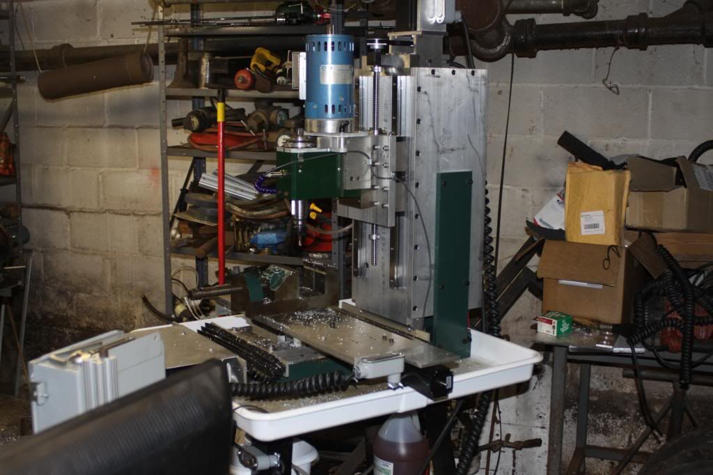
I don't know about the strength of your linear slides. He is a picture of the one I built with standard aluminum plate. And a cast-iron right angle plate. Plus steel flat stock check out my posts for the build here is a picture. The week point of mine was I got used linear rails and bearings from eBay for the X and Y they are not preloaded and have a little bit of play. But if I invest some new bearing blocks should be very good

 Reply With Quote
Similar Threads
-
All Parts "Off-the-Shelf"
By Plan_B in forum CNC Wood Router Project LogReplies: 15Last Post: 07-16-2011, 02:20 AM -
Mini Mech Mate - off the shelf parts
By nguyenst in forum CNC Wood Router Project LogReplies: 50Last Post: 03-16-2010, 07:52 PM -
proseries bedmill
By sindychen in forum News AnnouncementsReplies: 4Last Post: 12-21-2009, 02:42 AM -
Simple Printing on Vinyl with basic inkjet printer
By FrmDstryr in forum Printing, Scanners, Vinyl cutting and PlottersReplies: 9Last Post: 10-23-2008, 03:15 AM -
Assemble linear-actuator using off-the-shelf parts for < $600?
By offtherack in forum Linear and Rotary MotionReplies: 3Last Post: 04-22-2008, 08:42 AM
