


Hey guys,
This post will be a log of my new metalworking cnc build. I will start from the very beginning, and hopefully be able to keep you guys updated as I progress.
I must start by saying that this is a learning experience, and the primary reason behind this project is for education. My secondary reason for taking on this task is that too many people say it's not possible. It is possible that this project may become joint effort between some fellow college students, but for now, it is just me.
Let's start with some brainstorming:
--option 1--
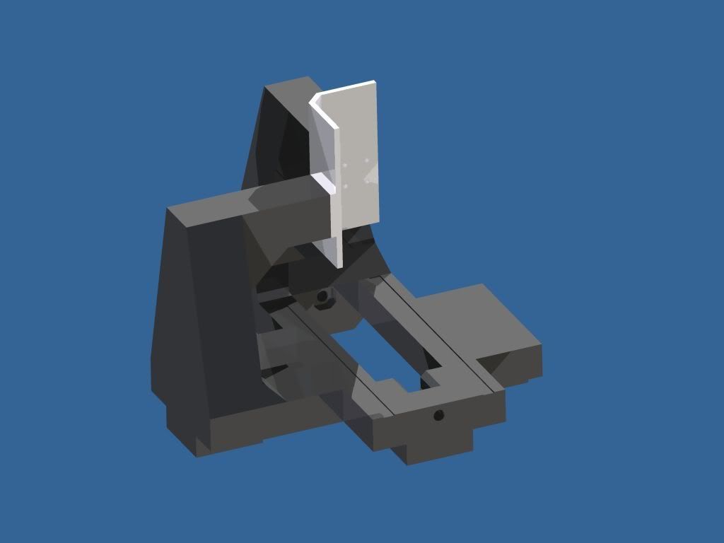
It's late now, but I thought I would throw up a super rough sketch of an idea that I had for a machine in order to give you guys an idea of what I am shooting for.
Here are some details that I have thought of for the machine pictured below.
-Epoxy-granite base poured around a welded steel frame (I've been keeping a close eye on the epoxy-granite thread!!!)
-Unique? double support for spindle
-24" x 24" table with 24" x and y travel; 16"-20" z travel
-THK (or similar) lm guides
-diy bt30 spindle; 2-5hp??
-??tool changer??
-ground ball screws
-run mach 3 or 4
-gecko drives (grex g100??) or similar
I have thought a little about the electronics on this machine, and to keep things super simple, this machine would run nema 34, 1200-1500 oz/in steppers on all axes. That's as far as I've gotten. I know some will say that if I am putting all of this time and money into this project, I might as well use servos, but I have yet to read anything that would say that some nice pac sci steppers couldn't do this job. I think I want to start out with steppers, I can always upgrade later, right?!
As you can see, the picture just shows the e/g base and spindle mount for now, but I will add more soon(spindle, frame, rails, motors, etc.)
Comments?? Warnings??
I know this is a little different than what most do around here, but we all like different right?
Sorry for all of the questions marks, as you can see I am just in the beginning stages.
Has anyone ever heard of getting some kind of grant, for this type of work in an educational setting? I'm gonna look into it!
Results 1 to 20 of 43
-
09-07-2007, 07:47 AM #1
 Member
- Join Date
- Feb 2007
- Posts
- 133
a machine design (pics) from beginning to end
-
09-07-2007, 02:01 PM #2
Registered
- Join Date
- Mar 2005
- Posts
- 1136
I like the two column support, one of the toughest areas to create rigidity and who doesn't like to see innovation. I've long thought epoxy granite with fabricated steel structure (normalized) could provide a best of class performance that was also diy accessible. My thought had been a steel exoskeleton - the steel becomes the mold - but there may be complications with this i haven't thought of. On reason i like it was all kinds of bits and pieces could be welded on prior to normalizing whereas it might be more difficult to attach to the epoxy granite.
Were it me, I'd be thinking of the following.....
this is a big machine. big is great, but costs and time to construct go up in a non linear relationship. larger machines are required to make it and and purchased components are a lot more expensive. Of course the required work envelope varies by application, but your talking building a machine with the work envelope of a full sized mill - that's ambitious. Consider reducing the size - it'll still prove the concept and do excellent work - do you really need that large a work envelope? what type of shop do you have access to?
They other idea i've want to try is using Newall encoders rather than rotary encoders - this would mean going servo rather than stepper. Their accuracy is amazing and the mechanical aspect of rotary encoders is eliminated. Since you're going high end on everything, using these encoders and the accuracy they bring would create a three axis platform that could be used for just about anthing (a wire edi head?). Why wouldn't you go servo for a machine like this?
i look forward to future installments
-
09-07-2007, 03:28 PM #3
Member
- Join Date
- Feb 2007
- Posts
- 133
Thanks for the input, I've got to run now so I'll try and go into more detail later, but just a few points.
I am going to try and make the purchased products as minimal as possible, except for the necessary components(rails, bearings, tooling, motors, etc.).
I like that you used the word ambitious, as that is what I am shooting for. "GO big or go home right!" lol
More on servos later.
Any more opinions on the double column spindle support?
-
09-08-2007, 12:47 AM #4
Member
- Join Date
- Feb 2007
- Posts
- 133
 Originally Posted by Mcgyver

Okay, so I have a little time to rant about this project. As far as servos go, I just want to start with steppers, and move up from there. I would like to get a little experience with the stepper motors, and then eventually replace them with servos. I can then use those steppers for a future router build!
Ever since the first time I read an article about steppers vs. servos I've kind of sworn off servos for my first attempt.
I'm gonna work on these drawings a bit more so I can post up some pics!
-
09-08-2007, 03:27 AM #5
Member
- Join Date
- Feb 2007
- Posts
- 133
Here's a couple more pics with some extra stuff attached:
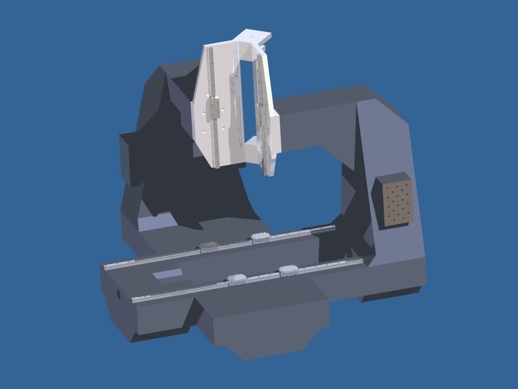
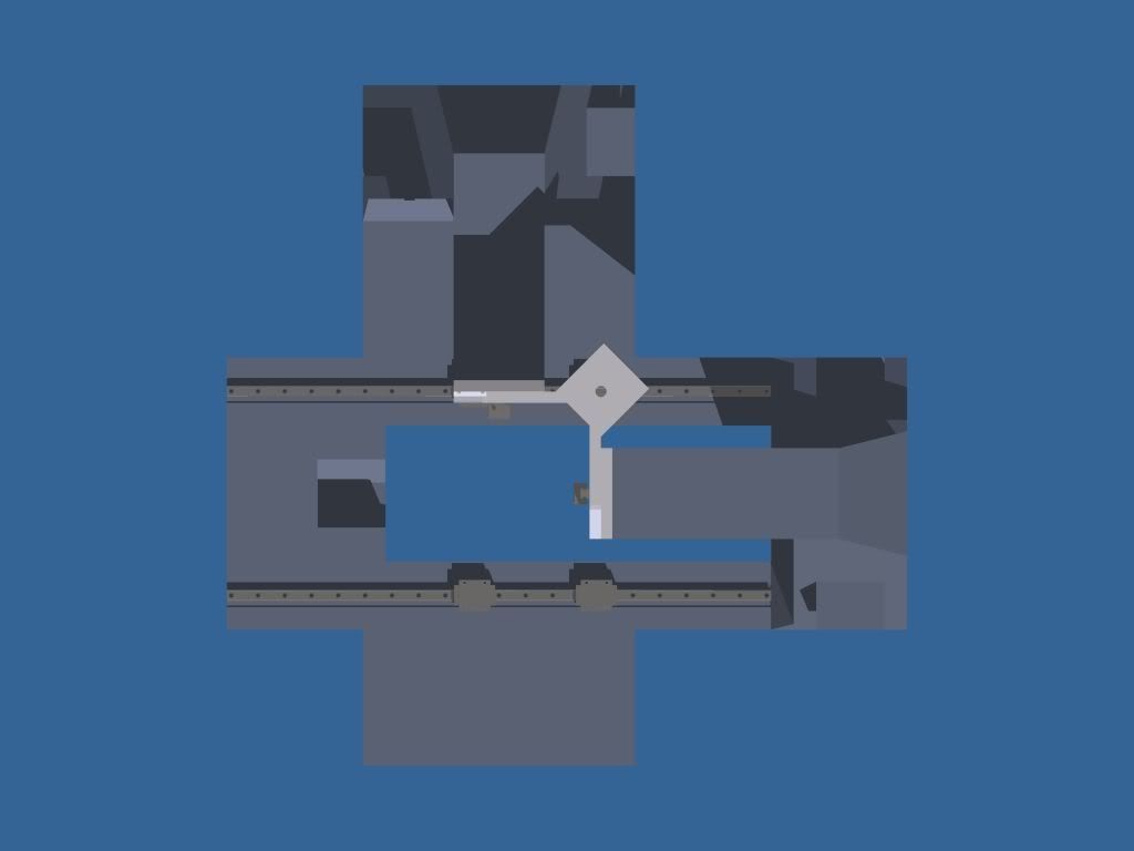
I'm gonna focus on some renderings for the spindle next, so I'll get those up as soon as I can!
-
09-08-2007, 06:30 AM #6
Gold Member
- Join Date
- May 2003
- Posts
- 792
What a cool design! I will be following this thread with interest.
Here's my opinion (which is completely uneducated- I know metal mills only from pictures(!) So please don't take it seriously).
IMO You won't be able to mill metal with this two column design and 16" of Z axis - even if it was made of solid cast iron. It would be a solid wood mill -if it was entirely made of cast iron- the whole machine. And you still wouldn't get 16" of Z axis.
I'm not sure about steel tubing properties but E/G is much weaker than cast iron.
For metal milling I would join the two columns and go all the way to the base- from both sides and cast it as a single piece of reinforced E/G. The whole thing.
Still, it is a beautiful design and I would love to see it implemented the way it is- it's a real show stopper and I've never seen anything like this. Very unique.
Walter
-
09-08-2007, 06:38 AM #7
Member
- Join Date
- Feb 2007
- Posts
- 133
Any way you could sketch that out for me walter? i'm not quite understanding what you mean. Originally Posted by walter
The idea behind this design was a sort of morphing of a gantry style mill and a knee mill in order to get the best of both worlds.
Keep the comments coming!
-
09-08-2007, 09:33 AM #8
Registered
- Join Date
- Sep 2006
- Posts
- 318
Just a quick question - design looks very industrial - It may be just me as I am not an engineer - Are you going to have the table moving left to right?
I was going to ask another question but having re read thread I realise it would have been a stupid question but will ask it anyway - do you not need 3 axis to be moving - I can see how the z axis will move and the y axis but not the x?
Regards
TonyDrakkn Custom Shop http://www.drakkncustomshop.co.uk
-
09-08-2007, 02:22 PM #9
Member
- Join Date
- Feb 2007
- Posts
- 133
Yeah, it is a 3-axis machine. I just have had a chance to model the table onto it yet, but the x-axis will sit on top of the y-axis.
-
09-08-2007, 04:22 PM #10
Registered
- Join Date
- Jul 2005
- Posts
- 969
nice project at around what amount do you estimate the cost of building such a monster cuz 24x24x16 is huge cannot be called hobby mill at that point
-
09-08-2007, 09:30 PM #11
Member
- Join Date
- Feb 2007
- Posts
- 133
Originally Posted by ataxy
Awww... somebody had to mention money and ruin all the fun! Just kidding. Well... I really haven't gone into pricing a huge amount, but I'm pretty good at eBay! With the vast majority of the parts being built by myself and other college students(slave labor) I would guess somewhere between $4000 to $6000! + huge amounts of time! I know a bunch of people are gonna suggest otherwise!
I may come up with a more accurate when I decide on a final design.
-
09-08-2007, 10:21 PM #12
Member
- Join Date
- Feb 2007
- Posts
- 133
Do you guys think I would have enough power in some 1400oz-in steppers?
-
09-09-2007, 08:46 AM #13
Member
- Join Date
- Feb 2007
- Posts
- 133
Anybody have any opinions on pac sci steppers? What drivers are people using for the big 1500-3000 oz in motors(7+ amps, 80v+)?
-
09-09-2007, 01:07 PM #14
Registered
- Join Date
- Jul 2005
- Posts
- 969
it will all depends on the weigh of the table and vise and all ounce you are done but 1400oz is pretty strong
-
09-10-2007, 12:33 AM #15
Gold Member
- Join Date
- Aug 2006
- Posts
- 1602
You'd proably have plenty of torque, but a poor top-speed and quite possibly acceleration due to the inertia of the massive motors. Originally Posted by blurrycustoms
Some people might say that speed isn't everything, but IMHO with the work envelope you're going for, you will need to have a pretty rapid machine to make large workpieces machineable in a reasonable time frame.
As others have said, 16" of Z will be interesting - you will need a very stiff 'ram' to mount your spindle on, which will make it really heavy. You will also have the problem that the spindle will be at it's most floppy right above the table where it will probably spend most of its time, but this is an inhererrant problem with gantry mills too. IMHO, you might be better off with fixed blocks on the Z and moving rails on the Z-ram/spindle. That way, there will always be a bearing block at the very base of the Z-support, which is obviously the closest point to the table surface.
Best of luck - this does look like a very interesting project :cheers:
-
09-11-2007, 07:16 AM #16
Member
- Join Date
- Feb 2007
- Posts
- 133
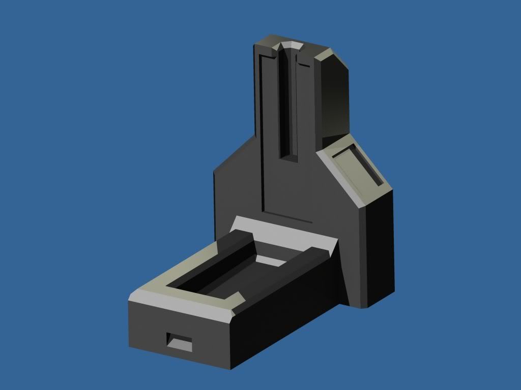
Here's a second option for me. Much more traditional, but take some "if's" out of the equation, specifically in regards z-axis travel.
Travel on this machine would be something like:
X - 30"
Y - 18"
z - 16"
Still a ton of work area. The picture below is just of the EG base. I'm working on the renderings for the steel frame right now!
Again this is not the standard cnczone machine, and I'm thinking about a 6'X6' footprint. And the way it's looking right now, it'll be pushing 2,000 lbs.
I think that the real trouble I'm having is trying to figure out how extreme I can go with the z-axis. There's just so much weight that the z motor has to accommodate, and still provide some hint of performance. Any suggestions.
-
09-11-2007, 08:16 AM #17
Gold Member
- Join Date
- Aug 2006
- Posts
- 1602
The obvious thing to counteract Z-axis weight is a counterbalance for the head. If you design it in from the start, it should be simple to implement.
Does your new design have 18-20" of 'throat' on the spindle - I'd be worried about that big a cantilever myself, but it does get done in industrial machines.
-
09-11-2007, 10:12 AM #18
Registered
- Join Date
- Jul 2005
- Posts
- 969
well one thing is for sure, ounce you are done with either choice this is going to be one hell of a homemade machine
-
09-11-2007, 01:28 PM #19
Gold Member
- Join Date
- Jun 2004
- Posts
- 6618
I liked your first idea, but it does limit lengths of stock that you could machine. The last design doesn't limit length. Not that you would need to mill longer stuff very often, but you never know.
The first design looks like the Z is more stable.
Have you considered a full bridge type gantry? I am building a mill like your last style, but have thought that a bridge would really add some strength and rigidity to any Z axis.
I built my router this way and it easily handle aluminum now.
Since you are still in the design phase, you might consider the bridge type.
Look forward to seeing your progress.Lee
-
09-11-2007, 03:19 PM #20
Member
- Join Date
- Feb 2007
- Posts
- 133
I'm not too worried about the weight on the linear bearings(mabe i should be though!), but more on the motor itself. That z-axis, with that large of an extension (18") could quickly turn into a 150-300lb mass. That's a lot of weight for that motor to move up and down! Even on a servo! Hmmm... I'll have to think about that one! Maybe, I would like to stay as close to a 16" z-axis as possible. Originally Posted by digits


 Reply With Quote
Similar Threads
-
New CNC machine build (big pics)
By ckm in forum Vertical Mill, Lathe Project LogReplies: 15Last Post: 04-30-2012, 11:49 PM -
My first build log of my belt drive DIY CNC Machine - PICs
By studysession in forum DIY CNC Router Table MachinesReplies: 16Last Post: 03-23-2012, 05:10 PM -
Pics of my new CNC machine
By monte55 in forum DIY CNC Router Table MachinesReplies: 26Last Post: 11-26-2007, 05:21 PM -
Bridgeport series 1 MDI machine pics and questions
By boringmill in forum Bridgeport / Hardinge MillsReplies: 3Last Post: 04-06-2006, 11:30 AM -
Machine building update pics
By CRFultz in forum DIY CNC Router Table MachinesReplies: 2Last Post: 10-23-2004, 10:42 PM
