


Hi again,
I'm new here with tons of questions. Please bear with me if this seems really basic.
Setting Tool Lengths:
Basically I am trying to set up my tool table so Mach 3 knows how long each tool is. I have the Tormach ETC (electronic tool setter). I followed the directions in the manual for setting up tool lengths with the tool setter. First of all, what is a 'master tool'? Is that just any tool I decide to call my 'master'? What should it be and why?
I put a random end mill into the spindle, and carefully touched it to a piece of .005" paper on the table. I typed .005" into my DRO Z position and pressed enter. Then I raised up the spindle and clicked [Setup Sensor Height] and it gave me something like 3.1542 which seems to make sense.
Then, I pressed Setup Tool Length and it says the length is .0000. That's because the length relative to itself is 0, right? Then, any subsequent tool I measure is recorded in the tool table as a +.2612 or -.3710 for example, their lengths relative to the 'master' tool. This is different than the common method of using a granite block and actually entering lengths from the spindle face to the tip of the tool. Is it effectively the same thing?
SprutCAM
SprutCAM has a tool list that I must populate. Are the tool numbers referenced in this list the same as the tool numbers in my Mach3 tool table? When SprutCAM asks me for a tool length, is that simply a rough length for simulation purposes, versus the exact length I am entering in my tool table?
Thanks to anyone who can give advice here. It's a little overwhelming getting started.
Results 1 to 20 of 25
-
09-07-2013, 07:21 AM #1
 Registered
- Join Date
- Sep 2013
- Posts
- 183
Confused about setting up tool lengths
-
09-07-2013, 07:57 AM #2
Registered
- Join Date
- Feb 2007
- Posts
- 664
master tool , yes you can use a tool for this and all the other tools will be referanced off that tool
using a tooling ball is a much better way to go , that way it never changes and all tools will referance off the tooling ball
you will also set your part zero off this tool ( tooling ball or tool from your set up)
a tooling ball looks like a ball with a stud coming out of it and you put it in your tool holder just like an end mill
you can also use a pin with a flat bottom , radius , as long as the point of contact is the same when setting tools or part surface
-
09-07-2013, 07:58 AM #3
Registered
- Join Date
- Feb 2007
- Posts
- 664
also if the tool is longer then the tooling ball the offset will be in the plus , if the tool is shorted it will be in the minus
-
09-07-2013, 08:05 AM #4
Registered
- Join Date
- Feb 2007
- Posts
- 664
SprutCAM , i don't think it matters if you put the offsets in , just the tool numbers and yes tool #'s are the same for both
some cam software needs a tool offset if it's tilting the spindle axis , but you just using 3 axis
-
09-07-2013, 08:26 AM #5
Registered
- Join Date
- Sep 2013
- Posts
- 183
Thanks for the response holbie. Does anyone ever use an edge finder in place of a tooling ball?
In SprutCAM, I am just inputting the length and toolholder dimensions so it can simulate more accurately. There are other variables I haven't messed with.
-
09-07-2013, 09:59 AM #6
Registered
- Join Date
- Feb 2007
- Posts
- 664
you can use anything that repeates
-
09-07-2013, 10:13 AM #7
Member
- Join Date
- Jun 2008
- Posts
- 1082
Be happy that you're using the tool height table from the very beginning! Believe me: setting the tool height at every tool change is a total pain in the ass and it's fraught with error potential.
It sounds like you've basically got it, so I'll just touch on one point...
For each tool you'll enter the full length. This is for the master tool and every other tool (well, every tool I'm aware of, I imagine there might be rare exceptions). So, if your master tool is 3" long and you have an end mill that's 2.75" long you would enter "3.00" and "2.75" into the tool table. You would not enter anything like "-0.25" for the end mill. I would, personally, measure the height of your master tool in your height-measuring rig and enter that value as "tool #1" in the tool table. Originally Posted by cobrakai

Before I go on too much I will say that I'm a novice. "CNCing" is a hobby for me - I've *tried* a fair amount of stuff but unlike some people on this forum I don't do this stuff as a profession and I do not have years of experience. I'm not the most experienced machinist, but I am pretty good at writing very long forum posts...
...
As for a master tool that would be good to use I would definitely recommend against anything rigid. None of the traditional edge finders that I'm aware of would be very good - in my opinion. The trouble is: if you accidentally go too far down with a rigid tool you might ruin something. Most obvious is that you might gouge the stock (or whatever other surface you're indicating off of). I suppose you could hypothetically damage the machine itself. You could also potentially damage the tool. If you're using an end mill you could break off a little piece of one of the flutes or something. With a normal edge finder you might push it into its collet a tiny bit. Anything you use might bend or something too. If you notice that it's happened some of these things might not be so bad, but if they're subtle enough that you don't notice you might find that parts start getting ruined and it might be tricky to figure out what went wrong.
If you're looking for a very good master tool I would recommend a Haimer Taster. They're awesome. They're also very expensive (~$440). A Taster will let you find edges and top of your stock. I don't think it'll do much more. Mine seems to be just about as accurate as I could hope for and seems like a nice, solid instrument that will hopefully last me a long time. I haven't been using it long though - maybe it'll prove to be a piece of **** over time. I dunno.
Haimer seems to price-control so the price for Tasters seemed to be the same no matter where I looked. Here they are on Tormach's site...
33072 - Haimer 3D Sensor - New Generation (Metric) w/ TTS holder
Yes, they're really expensive. I would say there's a pretty good argument to be made that a "master tool" should be very accurate and so far the Taster has been the epitome of accurate, for me at least.
Another option is the Tormach Passive Probe. It'll find edges, the center of holes, and the top of the workpiece with ease. I think the Tormach Controller software will also let you find the center of 3D features as well - like you could find the center of the head of a bolt or something. They're definitely expensive at ~$256, but a little more reasonable than the Taster.
A probe also has other uses (like 3D "scanning" of sorts), but I won't get into them here for brevity's sake.
There are many companies that will sell you a touch probe. I've heard they're sometimes as little as $100 (though I couldn't find any). Below is Tormach's, but if you value price over simplicity it might be worthwhile to look for a different brand...
32309 - Passive Probe w /10mm TTS mount
I wasn't "blown away" by the accuracy of *my* passive probe. It is VERY convenient and quite cool though. It might also be a little unrealistic to expect perfect accuracy when using a "hobby" CNC mill anyway.
(For more on edge finder choices check out this recent thread: http://www.cnczone.com/forums/tormac..._good_old.html.)
There's also this thing...
31283 - TTS Touch Tool w/Mechanical Indicator and Box
I'm pretty sure they're suppose to be used for this purpose. Unlike the Taster and the Passive Probe this thing wouldn't let you find edges. I suppose it might be useful in other ways though - like to make sure a piece of stock was perfectly flat before engraving or something. I would, personally, re-measure it periodically to make sure it doesn't lose its calibration. I would also pick a mechanical (AKA "analog") one like this one over the digital one. I've found that I can't always trust digital instruments - sometimes they lose their calibration for seemingly no reason. If you can constantly check the calibration, like with digital calipers, it might be OK, but with something like this you might not notice a problem 'til it's too late.
I was using one of these for a while...
Mitutoyo 950-111, Zero Setter, .0005" X 1" Height: Amazon.com: Industrial & Scientific
It eventually got sticky and I couldn't trust it. Perhaps it was because I wasn't taking care of it properly. There are many Z height setters like this on the market - presumably some are better than others.
The last thing I'll mention is just using a simple ol' gauge block. Something like this...
Mitutoyo Steel Rectangular Gage Block, ASME Grade 0, 3.0 mm Length: Amazon.com: Industrial & Scientific
Pick whatever thickness you want.
I used one for a while and, honestly, I really liked it. There were a couple drawbacks though.
Basically what I would do is place it on the edge of my stock so about half of it was hanging off. I'd hold it in place with my finger. Then I'd lower the spindle/tool down onto the part that was hanging off. I'd lower it enough that it would actually tip the block a little. Then I'd move the block to the side of the tool and repeatedly try to slide it under the tool as I slowly raised the spindle up. Once the block slides under you know that the tool is very close to the thickness of the gauge away from the stock. Include the height/thickness of the gauge block in the height of your master tool and it should be very accurate.
I know I recommended against anything rigid and a gauge block is about as rigid as you could get. I would say this gets a pass since you are using your fingers to manipulate the block to ensure that nothing gets damaged.
Problems...
You have your fingers right next to the tool - conceivably not a good idea.
The block will get scratched - I don't think light scratches will make much of a difference, but I'm not sure.
To use the exact technique I described above your stock needs to be flat in at least one place and you have to find a place where the gauge block can hang off an edge. This technique also limits setting the Z height to the periphery of your stock (in most cases).
I've, unsurprisingly, never heard of a "tooling ball". I Googled it and they look pretty straightforward. I will say that I don't like the looks of them, but perhaps they're the best thing since sliced bread. I'm always looking for new/better stuff so if anyone out there can explain their virtues I would be appreciative!
-
09-07-2013, 12:00 PM #8
Registered
- Join Date
- Jan 2007
- Posts
- 1332
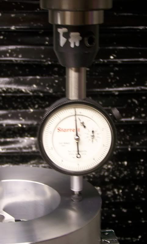
For setting up my tool table heights, I use a TTS AGD gage tool as shown below. The height of the TTS AGD gage tool (set at quarter travel 0.05”) and all other tools is measured offline on a surface plate using a height gage. I arbitrarily call this tool #1. I then measure the height of my reference surface with the TTS AGD gage tool in the Tormach spindle with tool #1 selected in Mach III. A huge advantage using the TTS AGD gage tool is that when set at quarter travel 0.05” there is a 0.15” overtravel when set in the Tormach spindle. In addition the spring loading at quarter travel makes the TTS AGD gage tool very repeatable.
AGD gages have a 4-48 threaded spindle in which a variety of contact styles can be used. I use an elephant foot contact with the TTS AGD gage tool to quickly touch off roll pins or tooling balls, as easily as flat reference surfaces.
If the Tormach 31283 - TTS Touch Tool looks like my TTS AGD gage tool that’s because Tormach modeled their touch tool after mine. Touch Tools « Milling Around
Don
-
09-07-2013, 01:56 PM #9
Registered
- Join Date
- Feb 2008
- Posts
- 389
You may want to check out this video tutorial by Tormach.
Part 2 is here...
Changing Tools in Mach3 (Part 2 of 2) - Tormach CNC - YouTube
GerryCurrently using SC7 Build 1.6 Rev. 64105
-
09-07-2013, 05:44 PM #10
Registered
- Join Date
- Sep 2013
- Posts
- 183
Wow, did not expect that! Thank you for taking the time to help me out and provide your inputs. Gerry, I did watch that video before and it makes a lot of sense. Unfortunately I don't actually have a height gauge. Yeah, it might be worth buying since I already have invested this much into the machine. Then again I thought hey, I have this fancy tool setter that is accurate to .0001 or something, so why not use it? Then it started confusing me by setting my master tool to 0, and every other tool relative to the master.
Hirudin, thanks for all the input on probing. You are indeed great at writing long responses. I think part of my confusion is not having seen anyone use these tools first hand so it's entirely conceptual to me. The only method I've used in the past on manual machines was marking the stock with a black sharpie, then bringing down the mill until it just takes off the black marking only. This can very accurately put you right on the surface of the metal since sharpie has some thickness to it. Of course, this is just dandy when you're machining something out of a raw chunk of metal since you don't really care as much. However it doesn't really fly when doing an operation on a previously finished part.
Don, it looks like the AGD tool (dial indicator) is the same method used in the videos, right? It seems like a pretty consistent method to me. By the way I checked out your focuser. Excellent work. It's a very nice design.
Alright I am going to give this another try today and report back hopefully with successful results.
-
09-07-2013, 11:05 PM #11
Registered
- Join Date
- May 2009
- Posts
- 327
I literally just set up my tts yesterday and this morning. One thing that I messed up on was when setting the initial 0 on z I forgot to select the tool in mach3. Luckily I caught it.
-Keith
-
09-08-2013, 04:23 AM #12
Registered
- Join Date
- Sep 2013
- Posts
- 183
Well it worked! Here is what I did, temporarily until I find a probe or better tool.
Touched tool #1 to the top of my vise and set tool length=0 and program coordinates=0. What was happening before is that when I set the tool length to 0, my program coordinates changed! So every time I measured a tool length relative to tool #1 it was giving me some random number like -2.5 and I was about ready to start smashing things.
Then I ran the ATC touch off routine and it set every tool relative to the master tool and stored the values. So my tool table looks something like:
Tool 1: 0.0000
Tool 2: -0.2615
Tool 3: 0.3712
I can confirm this does work. I used an edgefinder to set my XY zeros, and tool #1 to set my Z zero. The program ran just fine. Now I just need to find the best solution for a probe that can be my master tool instead.
-
09-08-2013, 07:53 AM #13
Member
- Join Date
- Jun 2008
- Posts
- 1082
Oh cool, I didn't think that would be the way it worked, but it makes sense I guess.
...
Wait, does it?
If tool #1 is "0.000" and tool #2 is "-0.2615" what happens if the length of tool #1 changes? Like if tool #1 breaks or something. Obviously, you could run the tool height routine again, but that doesn't seem that practical if you have a lot of tools.
I managed to rapid my Taster down on my workpiece so I had to replace the ceramic insert. The new one was something like 0.02 mm longer than the old one. In other words, the new tip was ~0.0008" longer than the last one. I would hate for that to mean you would have to add 0.0008 to all the entries in the tool table.
-
09-08-2013, 08:37 AM #14
Registered
- Join Date
- Feb 2007
- Posts
- 664
then you will need to reset the tools
-
09-08-2013, 03:43 PM #15
Registered
- Join Date
- Jan 2012
- Posts
- 789
Yes. All heights are relative to tool #1. If tool #1 changes, you need to update your other tools. Edited because I was wrong.
-
09-08-2013, 03:57 PM #16
Gold Member
- Join Date
- Feb 2006
- Posts
- 7063
Giving any real tool a length of zero seems odd to me, as it makes ALL tool lengths relative to that one tool. Simply set it's length to it's actual length, and if that tool breaks, you can replace it, update its entry in the tool table, and get on with your work. The whole "reference tool" concept is really not necessary, and you'll never have to update any tools length because some other tool got broken.
I set my fixture Z offset using a piece of 1/4" rod in a set-screw holder. This rod had a length of exactly 3" from the "collar" of the TTS holder, as measured with a height gauge. With G49 active, I touch off on the top of the workpiece, set the DRO to 3", and I'm ready to go. All tool table entries are simply the actual lengths of each tool, as measured with a height gauge.
There are at least a hundred different ways to use the tool table, and no single "right" way.
Regards,
Ray L.
-
09-08-2013, 04:06 PM #17
Registered
- Join Date
- Jan 2012
- Posts
- 789
I do what Don does, which is similar to what Ray does, except it's a dial gauge.
When Zeroing your fixture, make sure tool #1 is selected. Move down til the gauge reads zero. Zero you Z work offset. Then if the length of tool #1 changes, you just update the tool #1 length.
This is based upon offline tool setting with a height gauge. I don't know how it works with a tool length touch tool.
-
09-08-2013, 04:18 PM #18
Registered
- Join Date
- Jan 2007
- Posts
- 1332
I measure all tool heights offline on a surface plate using a height gage and enter each offline measured value in the tool table. Then each tool can be a reference tool when touching off in the Tormach spindle as long as the particular tool number that is used to touch off with is entered in Mach III when zeroing the Z-axis. I just like using the AGD gage tool to touch off with as the AGD gage tool has built-in 0.15” over travel. In fact I often will do a quick “check” of a particular tool height ( after Z- axis referencing with the AGD gage tool) by entering the particular tool number in Mach III and sort of “touching off” coming close to the reference datum with that particular tool.
Don
-
09-08-2013, 05:03 PM #19
Registered
- Join Date
- Nov 2006
- Posts
- 227
Maybe I'm just too old fashioned... In all the years I've been machining, I have NEVER used a tool with a negative length. The use of negative tool lengths can be contributed to improper understanding of how the numbers are generated.
Yes I know that mathematically, it can be worked out. Distributive, associative and commutative properties... Most basic math functions. In fact, they are the very core of the offset function.
In the beginning... We were taught methods that could be supported with actual measurements. The tool height data reflects measurements that can be quick verified using a pocket scale. If you have a correct part/fixture offset, the control can then apply the tool offset correctly.
If you want to use tool length offsets, you should set zero from a point common to all tools. (not from the business end of the tool) Zero needs to be set from the head region. Then, the tool length offset, is exactly the distance from this surface to the tip. The tool length! Once you learn to properly set part/fixture zero, any tool can be changed, with no effect on other tools. The same principle applies to diameter offsets. I have seen negative numbers used here also. You can't have a negative tool diameter.(Yes I know that mathematically, it works)
I too use an indicator to find zero. I do not include the tool when I set zero. The tool length is a separate offset. If used properly, the offset value, is EXACTLY the length of tool you see. It makes it really easy when I see an offset of 2.005 and I see 6" of cutter hanging out.
-
09-08-2013, 06:28 PM #20
Registered
- Join Date
- Sep 2013
- Posts
- 183
You guys are right. Using the negative offsets is confusing and when looking at all my tools lined up I can't easily say if my tool table is right or wrong.
I guess my issue is I was trying to use the z touch probe exclusively? Is there even a way to tell how long a tool actually is by using this touch probe without ever using a digital height gauge? The only thing that comes to mind, which I did try for a moment while playing around, is touching the spindle face to the touch probe instead. Then zeroing it, raising up the spindle and measuring each tool relative to this. That way it will give me actual lengths from the tool tip to the spindle face.
Of course it's probably no easier than just measuring them all offline and entering those numbers in the tool table.
Thanks for all the insight. At least now I understand the concepts and just need to find the best way to apply it.

 Reply With Quote
Similar Threads
-
setting tool heights . Confused <
By chrisnis in forum Mach Software (ArtSoft software)Replies: 1Last Post: 01-20-2014, 03:53 PM -
Setting tool lengths.
By mgill09 in forum Bridgeport / Hardinge MillsReplies: 0Last Post: 05-18-2011, 11:48 AM -
Confused about setting voltage at 10v
By Vogavt in forum Benchtop MachinesReplies: 3Last Post: 04-30-2011, 02:52 AM -
Setting Z (multiple tool lengths)
By Rot Iron Racer in forum Dolphin CAD/CAMReplies: 2Last Post: 10-01-2008, 03:17 PM -
Confused by tool libraries
By MichaelHenry in forum SprutCAMReplies: 8Last Post: 12-31-2006, 06:05 PM
