


Wow that was quick!Originally Posted by katran

By the way excellent work.all I need now is some aluminium plate scrap ... I have a couple of pieces left , from my other projects , if I'm lucky , I'll finish the
project in 2-3 weeks .
pics .
.................................................. ........................................
Results 21 to 40 of 111
-
09-29-2013, 02:28 AM #21
 Gold Member
- Join Date
- May 2005
- Posts
- 3920
-
09-29-2013, 10:40 AM #22
Registered
- Join Date
- Feb 2009
- Posts
- 118
Thinking about what ' wizzard' said , I made some tweaks ... the bearing block is wider now ( 50mm instead 38mm ) . I also made some
renderings to illustrate the usefulness of the third bearing ...I really think that it will increase the stability and stiffness of the spindle ...
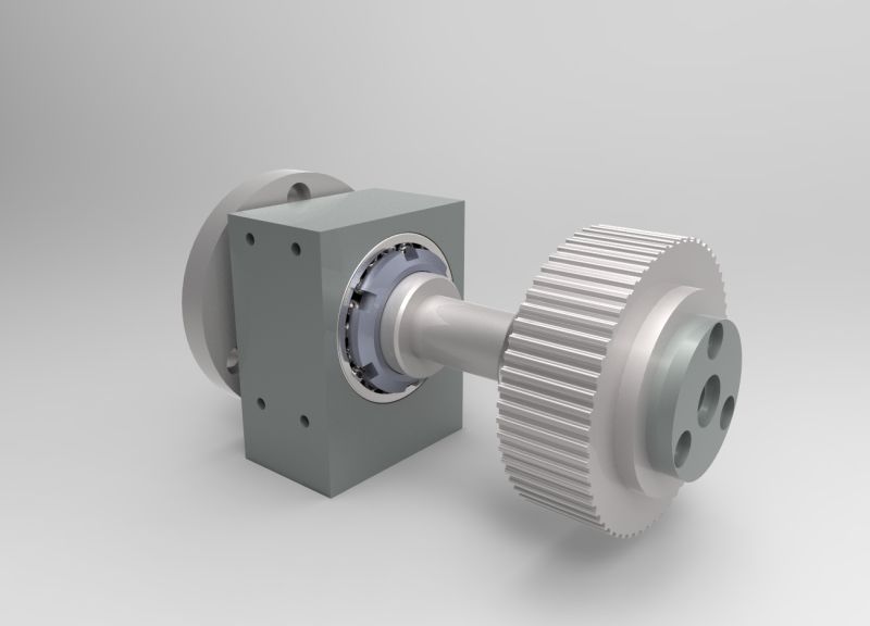
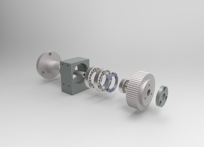
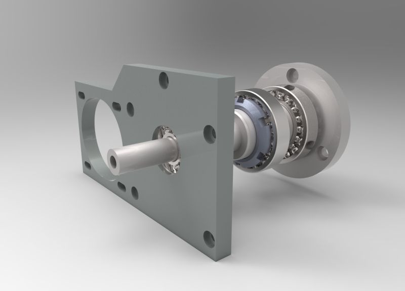
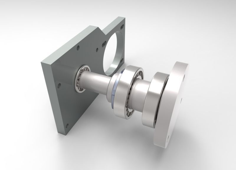
O.K then ... hope this is better ...
.................................................. ................................
-
09-29-2013, 01:44 PM #23
Member
- Join Date
- Jan 2005
- Posts
- 15362
Katran
Everything other posters have been saying have really been a none issue, with your design, What everyone has missed is the seals for the bearings, this is the most important part that has been missed in the design, Even a simple labyrinth seal you could add to what you have without to much of a problem
Don't worry about your chuck mounting, if you can bolt on a chuck to the flange, you can fix/bolt anything else the same way
As for the flatness of your base extrusion, it will work just fine for what you want to machine, this is not a very long piece so won't have much affect on your milled piecesMactec54
-
09-29-2013, 05:02 PM #24
Registered
- Join Date
- Feb 2009
- Posts
- 118
Thanks mactec54 , I really appreciate your posting .
The protection of the bearings is a problem ... I don't have room for any sort of sealing ( if you refer to rubber rings ...I am not sure
how are these things called in english ... ) . Labyrinth seal ? What is that and how am I suppose to implement this concept here ?
P.S , are you referring to this ? OIL SEAL RING
-
09-29-2013, 06:56 PM #25
Member
- Join Date
- Jan 2005
- Posts
- 15362
Katran
Yes those in the photo are called oil seals, a Labyrinth seal is a none contact seal that have small clearances between stepped faces, there are many types of seals, the most used would be the oil type seals, but they can get damaged by metal chips, when machining, you most likely do have some room, were you could make a cap to go on the front of your housing, you would not need much, 6mm would be enough, here is a photo of a labyrinth seal, to give you a idea of how you could make them, clearance in the Labyrinth seal, can be what ever you can make it, 0.1mm to 0.2mm, 0.2mm being the max clearance
On the tail stock you could make a cap with a flange, this would cover the whole bearing & lock nut, no seal would be neededMactec54
-
09-29-2013, 07:30 PM #26
Registered
- Join Date
- Feb 2009
- Posts
- 118
Now I get it !!! Is not complicated , and is very clever !!! Thanks a lot .
cheers.
-
09-29-2013, 11:55 PM #27
Registered
- Join Date
- Mar 2006
- Posts
- 2712
Ref. bearing seals. If you use proper grease, you could use Nilos seals. They are an SKF product made in Italy. We use them on our spindles in addition to sealed (lubed for life) angular contact bearings. No need then for a lube system. Keeps debris from migrating into the bearings seals.
Dick ZDZASTR
-
09-30-2013, 12:51 AM #28
Member
- Join Date
- Jan 2005
- Posts
- 15362
Richard Zastrow
The Nilos are very good, the standard Nilos would not be suitable, for Katran to use, in your case you already are using sealed bearings, the Nilos is protecting the rubber seals only, that is why Nilos is made in different styles, he would need the Labyrinth Nilos for it to be any good for his use, It will be cheaper for Katran to make his own, which are very simple parts to makeMactec54
-
09-30-2013, 08:26 AM #29
Gold Member
- Join Date
- May 2005
- Posts
- 3920
Exactly you don't want chips getting in your bearings. That would be the number one concern. If you are using flood coolant you don't want the lube to be washed out of the bearings either. Originally Posted by katran
Honestly installing a simple cap here would be better than nothing.
I would bother with fluid seals only if you intend to use flood coolant aggressively. Even then rubber doesn't last long around metal chips.I don't have room for any sort of sealing ( if you refer to rubber rings ...I am not sure
how are these things called in english ... ) .
I see people have already suggested Nilos rings and labyrinth seals. These would be ideal if designed into the machine. Since you are already started I might suggest simple caps that fit very closely to the spindle shaft. These can be rather thin and would be better than nothing
Picture are fantastic at explaining this:Labyrinth seal ? What is that and how am I suppose to implement this concept here ?
Labyrinth seal - Wikipedia, the free encyclopedia
Labyrinth seals - SKF.com/Products
Labyrinth Seal Principle, Efficiency & Materials | GMN Bearing, Ltd.
http://scholar.lib.vt.edu/theses/ava...o_R_D_2012.pdf (very Long paper related to turbo machinery.)
http://www.skf.com/binary/12-111147/...0-Nilos_08.pdf
Maryland Metrics: Introduction to Nilos Rings
P.S , are you referring to this ? OIL SEAL RING
-
09-30-2013, 05:57 PM #30
Registered
- Join Date
- Mar 2006
- Posts
- 2712
mactech, the Nilos seals work fine as grease seals. If you look in their tech sections in their catalog/manual, it is explained quite well. Also, they only need about 5mm clearance area to fit into.
I am ASSuming this axis will not have very high speed, hence my suggestion for grease lube. I think the Nilos seals would work fine, especially in a horizontal attitude. Yes, the Nilos labarynth and plastic filled seals would be superior. That's like me though, belt AND suspenders.LOL
Dick ZDZASTR
-
09-30-2013, 06:41 PM #31
Member
- Join Date
- Jan 2005
- Posts
- 15362
Yes that is correct they will keep the grease in, but will not keep the chips out, they just act the same way as a shielded bearing does, which is no good in any machining area were there is coolant, chips Originally Posted by RICHARD ZASTROW
There is no substitute for the real thing, Labyrinth is superior for this application & is simple to makeMactec54
-
10-06-2013, 05:42 PM #32
Registered
- Join Date
- Feb 2009
- Posts
- 118
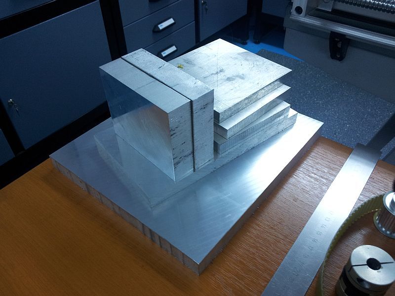
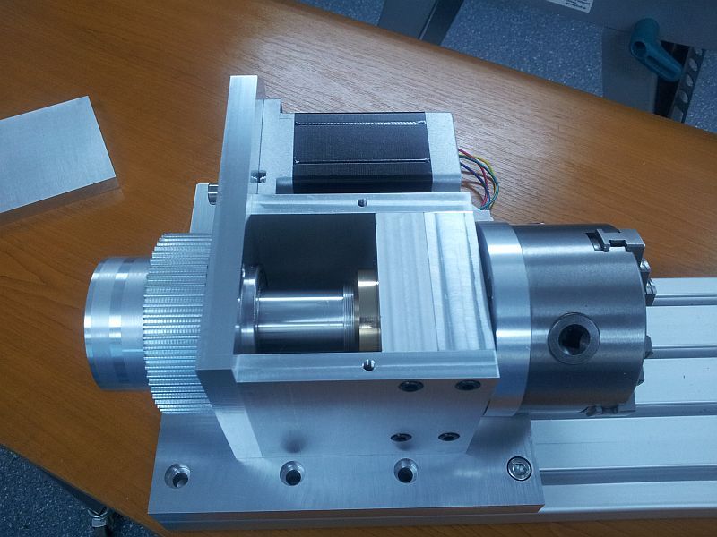
Update ....
Spindle ( bearings , retaining nut and 60 teeth timing pulley ) , and the aluminium plates needed for the job ... Is going
to be heavy ... around 10Kg . Hope this will not be a problem ...
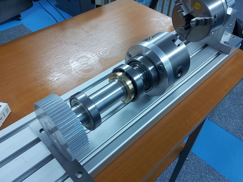
Very little time available for this project ... it will take a while ... Pfff ....
.................................................. .................................................. ..................................
-
10-11-2013, 12:47 PM #33
Registered
- Join Date
- Feb 2009
- Posts
- 118
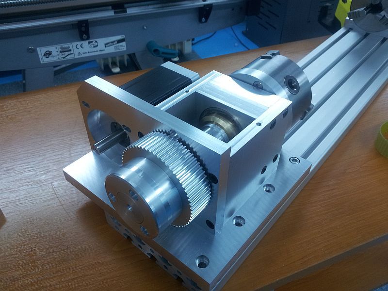
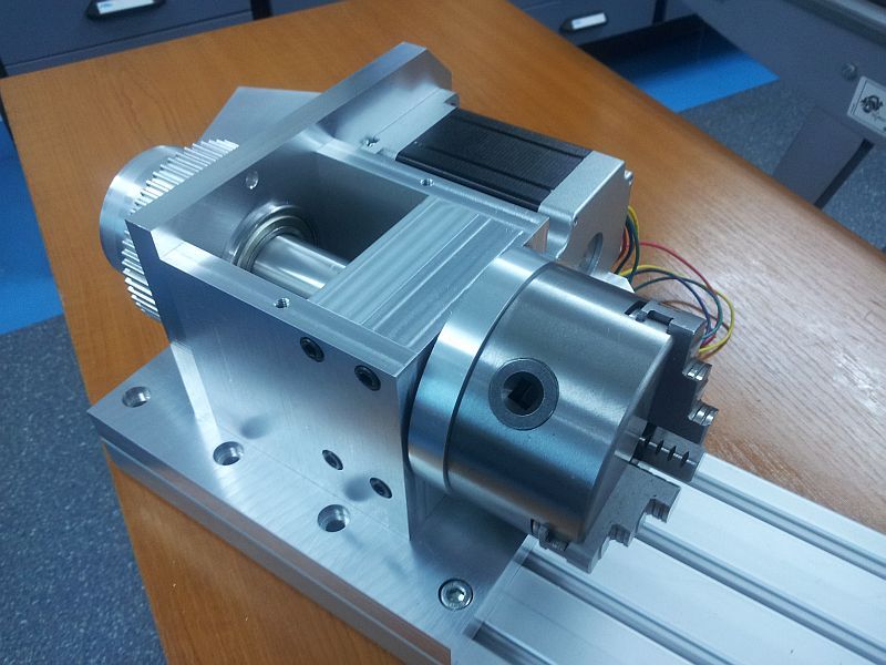
update ...

..............................................
-
10-11-2013, 01:34 PM #34
Member
- Join Date
- Jan 2005
- Posts
- 15362
For someone that had very little time to build this you have done a great job in a short amount of time, you are almost done, cutting some parts with it, will be worth all the work you have put into this 4th axes build Originally Posted by katran
Mactec54
-
10-11-2013, 03:49 PM #35
Registered
- Join Date
- Feb 2009
- Posts
- 118
Thanks .
As I said , I am an air traffic controller ... working shifts ( 12/24-12/48 ) I only have about 2-3 hours after night shift available for this
project . Spindle was done in 2 hours , aluminum components ( plates , 7 pcs. ) in 4 hours , assembly to this point about 45 minutes ...
I still have to mount the timing belt , the small ( 20 teeth ) timing pulley , make the wiring , and initial test . Hope to finish in a week or so ...
-
10-11-2013, 05:22 PM #36
Registered
- Join Date
- Mar 2006
- Posts
- 2712
katran, really nice work!!!
mactech54, I'm still defending my Nilos Rings. LOL
The sealing function of a Nilos Ring is accomplished by the LIGHT pressure the ring exerts on the bearing race.
"The fine labyrinth that is produced as a result prevents both leaking of grease and also the penetration of dirt [debris] into the bearing." Page 11 Nilos Ring catalog tech section.
We've been using those rings for years and never had any leakage or debris migration. As you correctly stated earlier, the Nilos interlaced labyrinth or the plastic filled seals would work better if the size katran requires is available. 'nuff promotion for today.LOL
Dick ZDZASTR
-
10-11-2013, 06:20 PM #37
Registered
- Join Date
- Feb 2009
- Posts
- 118
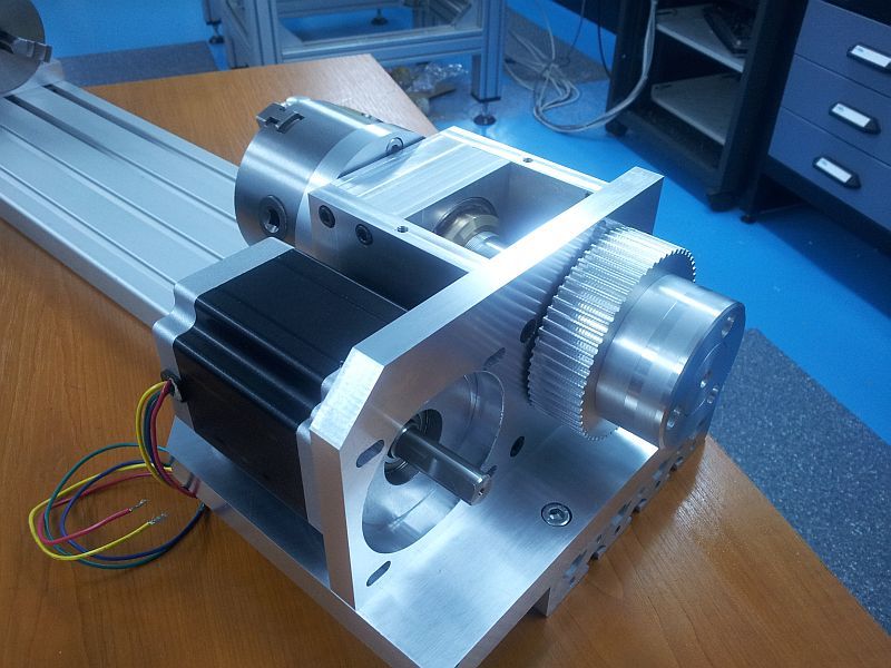
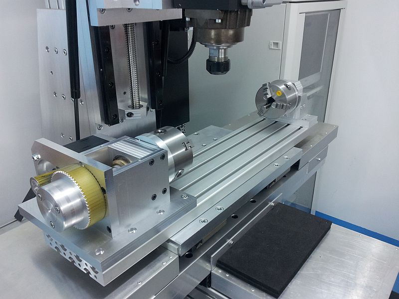
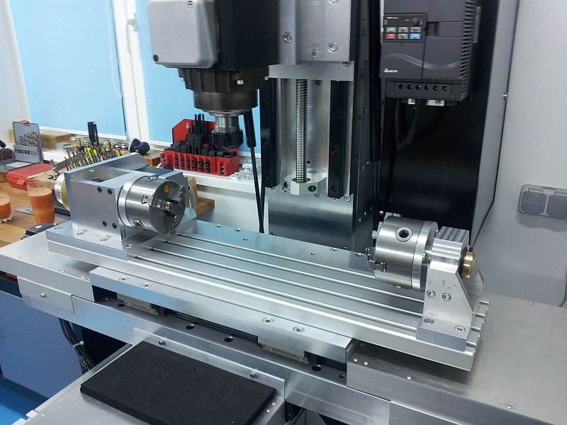
update ...
belt and motor mounted ...assembly looks O.K on the mill table , hope to test movement tomorrow .
.................................................. ....
-
10-12-2013, 12:52 AM #38
Gold Member
- Join Date
- May 2005
- Posts
- 3920
I have to agree with everyone else, very nice work.
-
10-12-2013, 01:21 AM #39
Member
- Join Date
- Jun 2010
- Posts
- 4256
Very, very nice.
Can I suggest just one small modification? As the design stands you have little real control over the amount of backlash you might get. Most of this backlash will come from the way the belt fits to the teeth on the pulley. Such toothed belts need a degree of tension to get the teeth on the belt to fully engage with the teeth on the pulley, and that tension can be quite high. Yes, you can apply tension to the belt just by shoving with your hand, but that is very variable and uncontrolled.
I suggest you could add a small tensioning adjustment on the motor, so you can adjust the tension and hence (most of) the backlash in the belt in a CONTROLLED manner. For instance, if you change one mounting hole from a slot to a pivot, you could use a small screw near the diagonally opposite mounting bolt to pivot the motor slightly to get more tension. There are other ways of doing this as well. You could then also figure out the relation between tension and backlash, and do any periodic adjustments needed in a controlled manner.
Cheers
Roger
-
10-12-2013, 04:36 AM #40
Member
- Join Date
- Sep 2006
- Posts
- 6463
Hi, this is a subject foremost in my mind at present as I'm just now entering into the real world of CNC machining, and the aspect of a 4th axis for DIY is where I'm at.
One question......would a conventional chain drive be more effective than a resilient toothed belt for the backlash prevention side?
Second question......in this design the stepper is on the side nearest the column.......would it be better to have mounted it on the front side to keep it clear of the column, even though when using the 4th axis the spindle is mostly on the centre line anyway and so clear of the column?
I would think the position of the stepper would be better if it was attached on the back of the frame not the front.
The last question is........why is there no guard or enclosure on the belt drive mechanism......chips and coolant in that area will play havoc with a timed belt drive mechanism.
It's a very neat build and well made, so my comments are just information gathering for when I do the same exercise for real, but as I will be attempting to use a set-up with compound gearing for the 1:60 reduction, I'll use this build as a watch point for comparison.
Ian.

 Reply With Quote


Similar Threads
-
Convert Gantry to Belt Driven Need little Help
By dbtoutfit in forum DIY CNC Router Table MachinesReplies: 5Last Post: 03-10-2013, 07:45 PM -
belt or gear driven?
By mikeph in forum Bridgeport / Hardinge MillsReplies: 2Last Post: 11-24-2011, 07:18 AM -
direct driven or belt driven
By jeremy0203 in forum Benchtop MachinesReplies: 5Last Post: 07-27-2011, 05:23 AM -
belt driven CNC
By jwest in forum DIY CNC Router Table MachinesReplies: 1Last Post: 11-29-2008, 11:10 PM -
Belt driven screw ?
By tomcat47 in forum Linear and Rotary MotionReplies: 10Last Post: 01-29-2007, 05:20 PM
