


I'm starting this thread as a place to discuss the nuances of the machine definition parameters and how those affect both the post processor system and the simulations. I think this is a complicated thing to understand well enough to take full advantage of, so probably a good thing to learn more in depth. I am not an expert, and figure I have more to learn than to share, so these are some of the things I've found hard to grasp or difficult to discern what the correct way to configure these parameters really is.
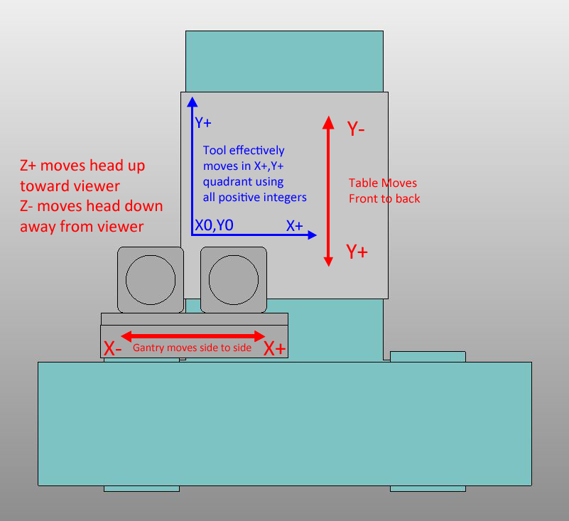
I'll start with a couple of observations that I find a bit confusing and hopefully it will spur some conversation. First, I understand that the "Direction" setting for each axis in the machine definition is meant to provide a reference for whether the machine is moving the tool or the material. If the Direction setting for X and Y is -1, it is moving the material, if it is +1, it is moving the tool. The main issue I have encountered is that if I set up the machine definitions to match my actual machine, it changes the output of the post processor to something that doesn't work in some cases. I'll try to articulate what I think I'm running into, but it will probably be a bit confusing to read, so hopefully it makes sense. Here's a sketch of my machine for reference, if you are looking at it from the ceiling down toward the table surface:
My machine move the table, and therefor the material, in the Y axis and as the diagram shows, a motion in the Y+ direction moves the table in a manner which causes the tool to move on a Y+ vector. Technically speaking, the table is probably moving in a Y- motion, but the controller is set up with the perspective of the tool to material relationship in mind, not whether the table is moving or the head is moving. I have retrofitted a controller to the machine, but this is the way that it was configured from the factory as well, way back in 1991, and a common arrangement in my experience. Setting this axis to a "Direction" of -1 works for this axis both in terms of how it outputs code and how it would simulate.
The X axis causes some problems. Since the head moves side to side, the "Direction" should be 1 to reflect that the tool moves, not the material. This produces X- (negative) integers where the part is in the X+ quadrant, opposite of what the controller wants. The problem is that if I were to set up the Y axis as suggested to a "Direction" of -1, I would have a mirrored part even if I zero the machine to cut the negative X integers where they should have been positive. Leaving the X axis set to -1 allows a part in the X+, Y+ quadrant to produce toolpath code with positive integers in the X,Y motions, as it should. But again that is the opposite of the instructions as I understand them.
The Z axis adds another problem I can't figure out how best to approach. For some reason, if you set up the X or Y axis with a "Direction" value of -1, you get unmolested integers back in the post processor. By this I mean that if the toolpath is in a positive value quadrant of the model/drawing, a positive integer will be used in the program by the post processor. If you set up the X or Y axis with a "Direction" value of 1, and the toolpath is in a positive value quadrant of the model/drawing, you get back negative values in the program by the post processor. The Z axis, however, does not work by the same rules. If you set the Z axis "Direction" to a -1 value, you get the opposite Z integer back as compared to the coordinate system used by the model. I you set it to 1, you get the actual integer back as compared to the coordinate system the model is in.
My machine move the Z axis up with a positive integer, and down with a negative integer. If I set the "Direction" to 1, I get the correct integers back for the machine to cut the part right. The problem is that because this is the opposite behavior of the X and Y axis, where you would set the "Direction" to -1 where the tool is moved in relation to the part (same as +1 for Z axis), you get an odd condition for the limits settings, which are also crucial for the simulation.
For my machine, I can't set up the X axis as a moving gantry (+1) unless I change the way the controller works (I could, but don't feel I should have to), or if I can prevent the post processor from reversing the +/- value of the integers. If I understand correctly, by not setting up the X axis to a value of 1, indicating the moving tool rather than table, I would not get proper full simulation either. An additional problem, caused by the Z axis being what seems backwards to me, is that I have to set up the Z limits to be opposite of what they are as well, which will probably cause problems with simulation yet again.
The real world coordinates that would trip my limit switches are as follows relative to the machine coordinates origin produced by homing the machine (in mm, sorry):
X-25mm through X+1550mm
Y-25mm through Y+1250mm
Z -200mm through Z+50mm
If I have my X, Y, and Z axis set to -1, -1, and 1 respectively for the "Direction" values, I have to enter the limits this way:
X Min -25
X Max 1550
Y Min -25
Y Max 1250
Z Min -50
Z Max 200
If I reverse the Z axis limits (which is how I think they should be), I get an error during post production and the code won't be produced at all, so I have to set up the limits this way. The problem is, that doesn't seem like it's reflective of what my machine actually is. The Z axis cannot go to Z200 in machine coordinates. It also goes farther than Z-50 in machine coordinates. The X and Y axis are normal but because the Z axis works backwards from the X and Y axis in terms of the "Direction" function, I can't set up the limits the way I think they should be. If the Z axis behaved like the X and Y axis, and produced positive integers when set to -1 instead of 1, I could set up the limits properly just as they are for the X and Y axis. Also, if I reverse the X axis as it seems the instructions suggest for the specific machine type, I have to reverse the limits there as well.
That's where I'm at so far, and while I can get the code to come out right, and I can see the simulation run correctly in the basic simulation mode, I find this to be a bit confusing and haven't been able to figure out how to get a machine configured that is, on paper, similar to mine without breaking the post processor to produce code it can't cut right. It would be great if people could share what they have learned about setting up their machines and what worked for you.
Hope that's a good start, and will appreciate any thought regarding what I'm doing incorrectly or what I may be seeing in the wrong way.
Results 1 to 20 of 83
-
12-06-2013, 06:09 AM #1
 Member
- Join Date
- Sep 2012
- Posts
- 1195
Machine Definition Parameters - Posting and Simulation
-
12-06-2013, 06:25 AM #2
Member
- Join Date
- Sep 2012
- Posts
- 1195
Made a few edits as I was already confusing myself just writing that!
-
12-06-2013, 06:41 AM #3
Gold Member
- Join Date
- Apr 2009
- Posts
- 3376
I really am not trying to follow this as it has nothing for me,BUT,would you not think that somewhere there should be documentation????????????Boy,down this road before.
-
12-06-2013, 09:20 AM #4
Member
- Join Date
- Oct 2004
- Posts
- 832
mmoe, where do you stand when operating the machine and which direction are you facing?
To my mind your setup looks backwards with respect to convention unless you were standing at the bottom of the page and looking towards the top but I suspect you are not.
Now not saying that is wrong, just saying it is not conventional and I think thats where things start getting confusing and I have not even thought about things with regards to BobCAD and it sim yet
Hood
-
12-06-2013, 10:27 AM #5
Member
- Join Date
- Sep 2012
- Posts
- 1195
Yes, you face the machine from the end of the table, so the coordinate system is 180degrees rotated from the normal operator viewpoint. For routers, I would say that it is conventional due to the nature of the work and how the machines operate. In most cases with machines like mine, you are cutting a large panel of one material or another. The homing of the machine in this configuration allows for more room to load and unload the machine when it is at machine coordinates home position. Many times you are gently sliding material onto the table, so having the front edge of the table all the way forward aids in this process. The material itself is also often placed in a less precise manner because it's held down with a vacuum pump pulling right through a 3/4" MDF spoilboard. You simply set your material on the surface of the MDF, turn the pump on and run the program. In special cases, fixtures are used, but they would also be vacuum fixtures for quick loading and unloading. I've worked on a few machines other than mine and owned a couple of large machines myself now, and so far this has been pretty much the standard. Originally Posted by Hood

You sometimes see the heads home to the other side of the gantry, but in that case, the coordinate system is just rotated another 90 degrees. I find it easier to picture the 180 degree rotation myself, and it's never really been an issue. Heck, until I updated my current machine, I had never had a toolpath to look at, so it really didn't matter which corner you butted the material against. There was no visual to compare the motion with on the screen. Just a program scrolling by.
-
12-06-2013, 11:38 AM #6
Member
- Join Date
- Oct 2004
- Posts
- 832
mmoe,
bit pushed for time but regards homing position and machine coords zero. You can home to any position and still have machine zero conform to the norm, just set a Home Off value in Mach equal to the distance the axis is away from conventional Machine Coords Zero. What would happen is when you home instead of the machine coords reading Zero they would read , for example +1575 (I think from your numbers above)
This was not possible in the CSMIO a while back but thankfully they decided to allow it as an option after me and a few others requested it, the option is in the last few plugins, its called something like legacy homing option.
Hood
-
12-06-2013, 02:47 PM #7
No posers
- Join Date
- Apr 2008
- Posts
- 1577
I think I was wrong about the - vs + in the "Direction" of the axis. I have a "standard" VMC configuration so I've not delved into this any deeper but I'm interested in getting it right.
mmoe or Hood, why don't we build one of your machines to test it out? I'm game. Once we have the machine components "built" it will be easier to visualize what is going on. You don't need full simulation to open a machine definition and play with the axis controls, you just can't simulate a part.
-
12-06-2013, 03:15 PM #8
Ghost
- Join Date
- Dec 2008
- Posts
- 4548
Hey mmoe, Originally Posted by mmoe
What is the sequence of the definition tree you have setup for the machine file? On a 3 axis mill, the x and y are coupled. On your machine, the z and x are coupled.
Can you post your machine file here so I can output code with it too. Seems you got everything going except the z?
Do you have stl files of your machine? If not, send a picture and some "very basic" dims of the machine and I'll make something that at least resembles it.
-
12-06-2013, 06:33 PM #9
Member
- Join Date
- Sep 2012
- Posts
- 1195
I'm in the process of creating the files for my machine, so I'll try and get some files up later today. I'm also trying to figure out how to get the Z to be a sub-category to the X axis so they are coupled like you say, but not having much luck so far. I do think that is a key bit that will fix my problems, but so far not cooperating. Working on machine model files right now, but here's a video so you can see how the machine work. At the end, the head goes to machine zero, so at that point the axis are pretty much at the home switches. Not a very exciting video, but I think it illustrates the motion well. Originally Posted by BurrMan
Shinx CNC Router with CSMIO IP A surfacing wasteboard shortened) - YouTube
-
12-06-2013, 10:10 PM #10
Member
- Join Date
- Sep 2012
- Posts
- 1195
I'm not going to have time to finish today, but here's where my model is at for the time being. I still have to add the heads, which are a bit complicated and will take some though to get the spindle centered in the right position with the end of the collet holder at the right height. I'll be able to finish up tomorrow sometime, but this file does have all the components for the machine, X axis, Y axis and Z axis in terms of motion. The motors raise and lower on the Z axis in addition to the Z axis travel, so not yet sure how to tackle that issue, but the dovetailed crossmember is the mounting plate for the heads and moves up and down to create the Z axis motion. Supplying in .SAT (it's metric, sorry) as I haven't yet split the machine into components. From what I see, you would have to create individual components (in some cases more than one for an axis) in STL format, but they have to originate in the correct position to correlate to the home position in order to move correctly in relation to each other during simulation. I've located the X and Y axis at their normal home position, so they each have 25mm of negative travel in each axis (I can extent it to 50, but need to make new home switch brackets to do so). The Z axis is in the neighborhood of the correct home position, but is subject to adjustment. The center line of the spindle will be about 390mm further from extents of the X axis carriage (first carriage mounted directly to the gantry), so basically there is quite a lot more to protrude from the current Z axis extents, which places the cutter pretty much at the edge of the table. It looks like a long ways, but the heads are huge and cantilever out there quite a bit.
https://files.secureserver.net/0svxgw6CLMJzBW
On the actual machine, the heads can be spaced across the dovetailed plate to allow specific distances between the heads, so that you can cut more than one part at a time and have them fit into the material right. Not sure if I'll ever be able to simulate that, but would be curious to know if it's possible. The problem is that the heads are not technically their own axis, they are both moved up and down by the same Z motion at the same time, so their ability to cut the material is determined by a pneumatic cylinder which puts the cutter in the lowered position. This is done via an M code and sometimes they work independently while other times they work concurrently.
-
12-07-2013, 08:28 AM #11
Ghost
- Join Date
- Dec 2008
- Posts
- 4548
Hey mmoe,
So I got a test setup and a draft config to look at. I made a video to show the machine sim in case you don't have the pro sim to see the machine. ALso attached the machine files and the test file.
Code output from the default HaasVF post:
Sim:Code:% O100 (PROGRAM NUMBER) (BEGIN PREDATOR NC HEADER) (MCH_FILE=4AXVMILL.MCH) (COORD_SYS 1=X0 Y0 Z0) (MTOOL T1 S1 D12.7 C0. A0. H76.2) (MTOOL T2 S1 D12.7 C0. A0. H76.2) (SBOX X0. Y0. Z-50.8 L400. W300. H50.8) (END PREDATOR NC HEADER) (FIRST MACHINE SETUP - Machine Setup - 1) (PROGRAM NAME - SHINX_TEST.NC) (POST - HAAS VF) (DATE - FRI. 12/06/2013) (TIME - 09:24PM) N01 G00 G17 G40 G49 G80 G21 G90 (FIRST CUT - FIRST TOOL) (JOB 1 Profile Rough) (PROFILE ROUGH) (TOOL #1 12.7 1/2 FLAT ROUGH ENDMILL - STANDARD) N02 T1 M06 N03 G90 G54 X243.269 Y243.269 S3880 M03 N04 G43 H1 D1 Z25.4 M08 N05 Z5.08 N06 Z2.54 N07 G01 Z-25.4 F1133.5917 N08 X56.731 F2267.1833 N09 Y156.731 N10 X243.269 N11 Y243.269 N12 G00 Z5.08 N13 Z25.4 N14 M09 N15 M05 N16 G91 G28 Z0. N17 M01 (NEXT CUT - NEXT TOOL) (JOB 1 Profile Finish) (PROFILE FINISH) (TOOL #2 1/2 FLAT ENDMILL - STANDARD) N18 T2 M06 N19 G90 G54 X243.65 Y243.65 S3880 M03 N20 G43 H2 D2 Z25.4 M08 N21 G00 Z5.08 N22 Z2.54 N23 G01 Z-25.4 F566.7958 N24 X56.35 F1133.5917 N25 Y156.35 N26 X243.65 N27 Y243.65 N28 G00 Z5.08 N29 Z25.4 N30 M09 N31 M05 N32 G91 G28 Z0. N33 G91 G28 Y0. N34 T1 M06 (END OF FILE) N35 M30 (END OF PROGRAM) %
shinx machine setup - YouTube
So I did see what you were describing too. The "origin" had to be set on the stock to match how the machine worked, then the "direction" tag in the machine definition for the x was changed to a positive value to have the x post out as positive numbers.
I also manipulated your model to set the zero point for the sim to work. I don't think it reads "machine home" and work cords. I think it reads WCS and work cords. So I set the zero point to be that corner of the y table you pointed as the 0 point, then I moved the x and z to be right on that zero point. I think that's the way it needs to be.
Maybe we can get Al to look and chime in too, to see if the reversed y and x travels are supposed to be handled differently.
There is also another transform in the definition called "machine" that I could find any reference to or understanding of how that might be used.
-
12-07-2013, 04:04 PM #12
No posers
- Join Date
- Apr 2008
- Posts
- 1577
Looking at Burr's setup and the one I built from mmoe's files it looks like everything seems to follow what I understood before. Everything is in relation to the machine base which should never move in Simulation when the focus is on the Machine. I haven't completely finished thinking it through but my intuition says:
Y direction is -1: in relation to the machine, the table (attached to Y) has to move in a negative direction looking at the top of the machine to acheive Positve movement (according to the tool).
X direction is +1: in relation to the machine, the head (attached to X carrier) moves in a positive direction to achieve Positive movement (according to tool)
Z direction is +1: in relation to the machine, the head moves in a postive direction to achieve Positive Z movement (according to tool)
or something like that
-
12-07-2013, 04:13 PM #13
No posers
- Join Date
- Apr 2008
- Posts
- 1577
Damnit, still don't have that right but it's too hard to edit on mobile

-
12-07-2013, 08:08 PM #14
Member
- Join Date
- Sep 2012
- Posts
- 1195
Thanks Burrman,
That's pretty close and it's cool to see the machine moving around the same way it does in the real world! I'll have to watch that a few times to figure everything out. It looks like the Demo version doesn't let you run the simulation with the machine, but you can view and manually move the machine around, so it will probably be January before I get to try the whole thing (plan to upgrade to V26 then). Hopefully I'll have the whole simulation system figured out before then, and I'll be off and running.
I'll work with what you sent as I get some more of the machine model done. The position of the X and Y axis will make more sense at that point. I think this will be good to figure out, since most large commercial CNC routers would work similarly to mine. The axis may be slightly different, but typically they are set up so that you are facing the coordinate system 180 degrees from what you see on the screen.
One thing I noticed is that the Z axis seems to be working right now while allowing the post processor to work right. It must be due to the link between the X and Z axis. I can now setup the limits to the correct values of -200 and 50 for the Z axis (previously I had to set them backwards to -50 and 200 just to get the code to post). I set the start position to 0 for all of the axis, and the machine ends up pretty close to it's natural home position. From there, it looks like I could use work coordinates to match those in the machine for the multihead positioning, but still need to figure out how to configure more than one head in the simulation. Great start though!
-
12-07-2013, 08:38 PM #15
Ghost
- Join Date
- Dec 2008
- Posts
- 4548
I'm still not clear on a few things or confident either... I'll wait to you can verify code at this point, or we get some input from BobCad.
I cant get initial values to do anything. So like on the multi axis posting page there is an option for real machine zero or work cords.
I was trying to get the machine to start off up in the corner like you had it, do the work cords, then end back up there with the G53, but cant get it to do anything except the work cords.
-
12-08-2013, 02:16 AM #16
Member
- Join Date
- Sep 2012
- Posts
- 1195
Here's a revision of the machine model. There seems to be something a bit off on the length of the table support, as the table should be closer to the heads. I'll have to measure that later and update it, but you can see that "Head 1" is centered just off of the edge of the table when at home. "Head 2" is set up normally at 12" O.C. from bit to bit relative to Head 1 (304.8mm). I use work offset G54 for Head 1 and G55 for Head 2 for most programs and they operate like a tool changer. In some cases, both heads are spaced a different distance apart (depends on the job geometry), and both heads get used at the same time. When that is the case, I run the offest based on Head 2, so that Head 1 is running an identical cut at whatever distance to the X+ is ideal for optimizing stock.
I still have to model the tool holders as well. I use a ER 20 collet adapter that fits into the 3/4" collet as already modeled in the heads. I'm probably being too particular I suppose, but it seems like the simulation is better with more accurate models than without.
SAT file format in MM again:
https://files.secureserver.net/0sfXI41k2U1Pzm
Another thing I wonder is if you can use more than one component on a given part of the machine. Can you use 2 or 3 different geometry files for the Z axis, such as keeping each head individual for example?
-
12-08-2013, 02:52 AM #17
Ghost
- Join Date
- Dec 2008
- Posts
- 4548
Well, sure. But you have to be able to control them, like an "A" or a "B" output? How do you control the selection and output to the 2 heads? Manually? Originally Posted by mmoe
Like now in the model, you actuall have 2 X and 2 Z areas. We could set those up to all move with the various commands. But I don't think there's a way to dynamically tell it "This time, use THIS head instead of the other one.
Also, your model has the components up and out and away from the UCS zero. I Want to fool around with this tonight to see if I can make it work correctly that way.
-
12-08-2013, 06:33 AM #18
Ghost
- Join Date
- Dec 2008
- Posts
- 4548
Ok, so I rotated the machine in the z and created some STL's and set all the settings so the axis move properly. I am going to reposition the Y and X and Z components of the model to zero out on that corner of the Y table listed as the cords zero point (same as the other machine)
I'm going to do some measuring on the model and figure some stuff out then check code.
If I get that going, I'll add an axis control for the second head to use B or something. We could then ask for some help to make a script that reads the work offset and outputs a B instead of a Z and run the second head. Or something like that. We may need to discuss how you use it. But later. No need overload right now.
-
12-08-2013, 07:51 AM #19
Member
- Join Date
- Sep 2012
- Posts
- 1195
Can you tell me what happens if you leave the UCS at the origin? Does it have to be rotated for a reason or can it remain at the origin? Since I can't make the machine simulate in the demo, I can't see what happens if you do that. I also can't send you a file since I'm on the demo version and you wouldn't be able to try it out except on another demo version, which also wouldn't simulate the machine. I can simulate the code I create just fine with the UCS left at the origin without the machine being shown (basic simulation) and it looks the way I'd expect it to on the machine. I set up the G54 and G55 work offsets to match a position just inside of the table edge so I know where to locate the material (with additional offset for G55 for reasons listed further down). Basically, when I program with the UCS at the global 0,0,0, and set G54 and G55 to the top of the material, it cuts the same way as it cut in the simulation you showed, but the part is rotated 180 degrees from the way it was in your video. I don't actually mind that it's rotated, and if anything I am so used to the 180 degree reversal from 15 years of seeing it that way that it's almost alarming to see it oriented the other way. I always know what the drawing looked like, and when I see the cuts, my mind is already revolving the expected result 180 degress.

Head 1 and Head 2 are manually positioned left to right, so for the most part, I think that variable can be ignored. If I need to simulate with a different spacing on the heads, I could probably more easily move the heads within the STL for that specific use, save it as a different STL and then switch the STL as needed for different spacings. For any spacing other than the standard 12" O.C., I would always have both heads down, so I could also position them both that way and then name the file something that makes the spacing and dual head cutting obvious. Not sure if it will ever simulate two heads cutting at the same time though, since it does so with only 3 axis of motion. Would be nice to see in a simulation as it would provide good insight as to whether or not the spacing is working out well or not.
The two Z axis are controlled by machine codes, not axis motions. The whole dovetailed plate moves as one unit up and down, while the two heads are each mounted on a pneumatically controlled set of profiled rails. I currently have the post processor set up so that if tool number 1 is chosen, the "t" value is added to "30" to produce the M code value. If tool number 1 is chosen in the programming of a toolpath, the t+30 produces a value "31", which produces a code of "M31". Tool number 2 produces a "M32" code, so on so forth. I had planned to have up to 8 or 9 heads eventually, but it will be even more complex when I get to that point. The post processor code I'm using to generate the M codes and inserted in the post processor in parts "2." and "3." is:
n," ",force_no_add_spaces,"G",t1," ","M",t2,default_add_spaces
where these values are produced from the tool number:
240. Amount to add to t to obtain t1?53
241. Amount to add to t to obtain t2?30
A tool number of 2 would produce code in the start or toolchange that says:
N12 G55 M32
This tells the machine to offset for head number 2 and move head number 2 down to the cutting position. G55 is setup to shift the head over by 12" to align it with the cuts head 1 would make, serving to work like a tool changer. If the tool is changed to head number 1, 3 or 4 (all that is currently possible), the offset would be changed accordingly to either G54, G56 or G57 and the M code would be M31, M33, or M34 to lower each head respectively. M5 cancels any head that is lowered by not only turning the spindle off, but also raising the head back to the up position.
I found it easiest to produce the needed code this way, but I suspect that I would have to go with some sort of program block in order to do it in a way the simulator would recognize, and that's getting into some pretty challenging code I imagine. Exactly why I avoided it when I first wrote my post processor.
I should create a file to show you how I normally program, then show a video of how the resulting code cuts on the machine. I'll make it something short so that you don't have to watch much, but it will be asymmetrical so that it's obvious what's going on. I'll also add a tool change so you can see how the two heads work as compared to the code that makes them work. I think that you can ignore where the operator panel is and pretend that the viewer is standing behind the machine. I think that the 180 degree rotation that the UCS is doing might make locating the material a bit more dodgy for routing. CNC router operators are typically used to setting the material to a corner that matches the 0,0 position in the drawing and hitting start, or adjusting the work coordinates to match the lower left corner as needed. For files with lots of parts, that might get a little trickier to locate if you're using fall off and working with a more random batch of nested parts. The UCS corner could end up being at a corner with no stock or parts. I'll see if I can draw up an example of that. It's just a difference between router operation and mill operation. I would guess that it's rare to have more than a couple of parts located on a mill, where with a router the can be dozens of small parts (like letters, numbers, shapes) that are all fit into material that may not even be a rectangle as it could be scrap (fall off) from a previous job in an L shape.
Part of what I was asking about the geometry (STL) files used for each component is if you can keep them separate for cosmetic purposes as well. It would be great if you can import an STL of just the MDF top on the table and make it look like MDF in color, while the subtable remains the machine color. Or the profiled rails separately from the main machine body so that you can color each in a more realistic rendering. I can see instances where this would add some polish to a presentation. Clients are always amazed by watching things like that and rarely enjoy watching the actual machine (deafening load, move much slower than you can simulate and lots of dust). It would also be cool to be able to emboss a number into each head, so the head number is obvious to anyone using the simulation. If you can import more than one file for each section, that would be possible. I've been trying to do so, but so far I get an error message when I set it up that way.
Thanks for the help as well. Hopefully it helps others figure this stuff out, but I'm glad to be moving in the right direction.
-
12-08-2013, 08:35 AM #20
Ghost
- Join Date
- Dec 2008
- Posts
- 4548
Yes, that is exactly what happens. And I think I remember it simulates ok. I just changed it because it was mirrored in the sim and I was trying to make it be exact. I would think if you already work this way and understand it, you could set the origin and x flip how you like and it wont change/hurt anything. Originally Posted by mmoe
I somewhat understand. That's a pretty cool setup. I don't think we could make the sim do "THAT", but to be able to sim your work, I think we could make a special "sim post processor" that outputs what we need, to use an "axis transform" to set the z heads up and down as you want. Right now I left them set how you had, with the one about 110 mm up from the other. But, it should be a cool project to do that. The only variable would be "I manually move the heads" and if you manually move them "exactly" like that. So, both STL heads would be set at zero, and the sim code would have one lift or down, or wherever, until called. I think we would need help with the scripting blocks to handle the output translation from your toolcalls into axis call though, it's up to you if you decided to do that...Head 1 and Head 2 are manually positioned left to right, so for the most part, I think that variable can be ignored. If I need to simulate with a different spacing on the heads, I could probably more easily move the heads within the STL for that specific use, save it as a different STL and then switch the STL as needed for different spacings. For any spacing other than the standard 12" O.C., I would always have both heads down, so I could also position them both that way and then name the file something that makes the spacing and dual head cutting obvious. Not sure if it will ever simulate two heads cutting at the same time though, since it does so with only 3 axis of motion. Would be nice to see in a simulation as it would provide good insight as to whether or not the spacing is working out well or not.
The two Z axis are controlled by machine codes, not axis motions. The whole dovetailed plate moves as one unit up and down, while the two heads are each mounted on a pneumatically controlled set of profiled rails. I currently have the post processor set up so that if tool number 1 is chosen, the "t" value is added to "30" to produce the M code value. If tool number 1 is chosen in the programming of a toolpath, the t+30 produces a value "31", which produces a code of "M31". Tool number 2 produces a "M32" code, so on so forth. I had planned to have up to 8 or 9 heads eventually, but it will be even more complex when I get to that point. The post processor code I'm using to generate the M codes and inserted in the post processor in parts "2." and "3." is:
n," ",force_no_add_spaces,"G",t1," ","M",t2,default_add_spaces
where these values are produced from the tool number:
240. Amount to add to t to obtain t1?53
241. Amount to add to t to obtain t2?30
A tool number of 2 would produce code in the start or toolchange that says:
N12 G55 M32
This tells the machine to offset for head number 2 and move head number 2 down to the cutting position. G55 is setup to shift the head over by 12" to align it with the cuts head 1 would make, serving to work like a tool changer. If the tool is changed to head number 1, 3 or 4 (all that is currently possible), the offset would be changed accordingly to either G54, G56 or G57 and the M code would be M31, M33, or M34 to lower each head respectively. M5 cancels any head that is lowered by not only turning the spindle off, but also raising the head back to the up position.
I found it easiest to produce the needed code this way, but I suspect that I would have to go with some sort of program block in order to do it in a way the simulator would recognize, and that's getting into some pretty challenging code I imagine. Exactly why I avoided it when I first wrote my post processor.
Yeah, I just had some guests arrive. I'll make a video a little later to show how and what I've setup and the limits and such.I should create a file to show you how I normally program, then show a video of how the resulting code cuts on the machine. I'll make it something short so that you don't have to watch much, but it will be asymmetrical so that it's obvious what's going on. I'll also add a tool change so you can see how the two heads work as compared to the code that makes them work. I think that you can ignore where the operator panel is and pretend that the viewer is standing behind the machine. I think that the 180 degree rotation that the UCS is doing might make locating the material a bit more dodgy for routing. CNC router operators are typically used to setting the material to a corner that matches the 0,0 position in the drawing and hitting start, or adjusting the work coordinates to match the lower left corner as needed. For files with lots of parts, that might get a little trickier to locate if you're using fall off and working with a more random batch of nested parts. The UCS corner could end up being at a corner with no stock or parts. I'll see if I can draw up an example of that. It's just a difference between router operation and mill operation. I would guess that it's rare to have more than a couple of parts located on a mill, where with a router the can be dozens of small parts (like letters, numbers, shapes) that are all fit into material that may not even be a rectangle as it could be scrap (fall off) from a previous job in an L shape.
I want to talk about the limits set, and how it relates to the sim operation and the size of the model components. I think the numbers in the machine definition mins and maxs have to take into account the initial start 0, and the actual geometry size of the stls and such. I'll attach the machine files and stls after the video, because we need to discuss the limits set and where you want, need them. I have to crunch some numbers too, before I can speak to it.
Yeah, I get it. The separate solids in your file can all be named and saved and grouped in the sim as needed. I was just mass grouping a lot of it to save time. We can figure that out later when we nail it down. In the machine file I send later, you'll see I started to separate things out more already, like Z table and head and spindle, and how there grouped in the definition. But that's a little later.Part of what I was asking about the geometry (STL) files used for each component is if you can keep them separate for cosmetic purposes as well. It would be great if you can import an STL of just the MDF top on the table and make it look like MDF in color, while the subtable remains the machine color. Or the profiled rails separately from the main machine body so that you can color each in a more realistic rendering. I can see instances where this would add some polish to a presentation. Clients are always amazed by watching things like that and rarely enjoy watching the actual machine (deafening load, move much slower than you can simulate and lots of dust). It would also be cool to be able to emboss a number into each head, so the head number is obvious to anyone using the simulation. If you can import more than one file for each section, that would be possible. I've been trying to do so, but so far I get an error message when I set it up that way.
We'll talk more later after I get you the latest info I have.

 Reply With Quote
Similar Threads
-
Simulation Pro - Setting up the Machine Definition
By SBC Cycle in forum BobCad-CamReplies: 23Last Post: 04-07-2019, 08:22 AM -
Need help on V25 Machine definition
By Troncatore in forum BobCad-CamReplies: 24Last Post: 02-06-2013, 05:16 PM -
Machine Definition help
By drupillow in forum MastercamReplies: 0Last Post: 04-24-2010, 12:04 AM -
Machine Definition
By rrbmachining in forum CamWorksReplies: 1Last Post: 02-21-2009, 12:04 AM -
fanuc control simulation + parameters
By Yossi in forum FanucReplies: 0Last Post: 10-21-2005, 07:22 PM
