


I am very green to this and cant find any answers so I will ask here. I found wiring videos but cant find specifics on using the relay pins. How do I wire my router through the C 11 BOB relays. Do I split my neutral on the router cord and run to the pins or the hot? Any help would be appreciated, cause I dont want to fry my new board.
Results 1 to 20 of 27
-
12-11-2013, 12:12 AM #1
 Registered
- Join Date
- Mar 2010
- Posts
- 68
How to wire Router through relay on C11 Board?
-
12-11-2013, 12:54 AM #2
Community Moderator
- Join Date
- Dec 2003
- Posts
- 24221
The neutral on 120v should go direct to the router, and the relay switch the live side.
Al.CNC, Mechatronics Integration and Custom Machine Design
“Logic will get you from A to B. Imagination will take you everywhere.”
Albert E.
-
12-11-2013, 03:25 AM #3
Registered
- Join Date
- Mar 2010
- Posts
- 68
Attachment 212776 First of all thanks for taking the time to respond and please excuse the crude drawing, but this is correct then ?
-
12-11-2013, 05:28 AM #4
Community Moderator
- Join Date
- Dec 2003
- Posts
- 24221
Actually I was helping someone else on a similar problem and got things mixed up, you should actually use the relay to control the low voltage input run contact on the VFD , the 120v supply should go directly to the VFD supply, unbroken, you can use a relay in the estop circuit to turn off the 120vac if you wish to switch power off of the VFD.
What VFD do you have?
Al..CNC, Mechatronics Integration and Custom Machine Design
“Logic will get you from A to B. Imagination will take you everywhere.”
Albert E.
-
12-11-2013, 05:37 AM #5
Registered
- Join Date
- Jan 2013
- Posts
- 119
NO !!!
The relays on the C11 board will not handle enough current !
You need to use these relays to control a larger relay.
-
12-11-2013, 05:31 PM #6
Registered
- Join Date
- Mar 2010
- Posts
- 68
I dont have a VFD or spindle and I know how to setup Mach. I just need to find out how to wire this up straight from a router. Thanks so far for not letting me burn up my board. Is there somthing Icould search or somewhere where I can find a schematic on this sort of wiring ? Thanks.
-
12-11-2013, 06:46 PM #7
Community Moderator
- Join Date
- Dec 2003
- Posts
- 24221
If you just have a router you will need to use the C11 relay to either pick up a power relay capable of switching the router power or use a Solid state relay.
If you want to run off of a Parallel port output, just search 2N7000 here for details.
Al.CNC, Mechatronics Integration and Custom Machine Design
“Logic will get you from A to B. Imagination will take you everywhere.”
Albert E.
-
12-11-2013, 07:06 PM #8
Registered
- Join Date
- Mar 2010
- Posts
- 68
Thanks Al. I probably wont be using a parallel port output. I guess I am still to dumb to understand. I wish there was a schematic of some kind somewhere. Someone I am sure has wired their C11 this way. Off to search more.
-
12-12-2013, 03:21 AM #9
Registered
- Join Date
- Mar 2010
- Posts
- 68
Is this how I should wire my router to the C11 Relay pins?
-
12-12-2013, 04:13 AM #10
Registered
- Join Date
- Mar 2010
- Posts
- 68
Here is a better drawing. Is this right?
-
12-12-2013, 04:55 AM #11
Community Moderator
- Join Date
- Dec 2003
- Posts
- 24221
Solid state relays are usually 3-35vdc on the input side, although you can get 120/240 models on the input side.
The C11 relay contacts would be used to switch the low voltage, this can be a separate supply or obtain it from the computer 12v such as a 4 pin HD plug etc.
The diagram does not really show how the inputs are switched?
I can put a diagram together if needed.
Al.CNC, Mechatronics Integration and Custom Machine Design
“Logic will get you from A to B. Imagination will take you everywhere.”
Albert E.
-
12-12-2013, 06:00 AM #12
Registered
- Join Date
- Mar 2010
- Posts
- 68
Please put me a diagram together. I am about to pull my hair out over this C11 bob. Thanks
-
12-12-2013, 08:11 AM #13
Member
- Join Date
- Sep 2012
- Posts
- 1195
As with all things on the internet, you should understand that I'm not suggesting I'm a licensed electrician and this information is to be used at your own risk. That said, this is how I think you should put it together.
First, I would go with a standard old school relay. They aren't that expensive and they do last a long time. The first diagram shows the general idea behind a relay. There is a coil, which is typically activated by 12 or 24 volts (more commonly 24v in industrial applications I find). When power is supplied to the coil, the current "Normal" state of the switch reverses. What is Normally Open will become closed and what is Normally Closed will become open. For both the C11 and the larger relay, you're going to want to use the Normally Open characteristic (N.O.). You can see that the power supplied through the green wire is connected to the red output normally in this example, but when the coil activates, the green arm will swing to the other post and complete the circuit to the blue output instead. Not all relays are configured exactly the same and this is just one example, so you have to test them for continuity to be sure you are getting the right behavior. The N.O. may be the outer or the inner output, and the volts in could be reversed with the coil as it's shown here, so you just have to figure out what you have.
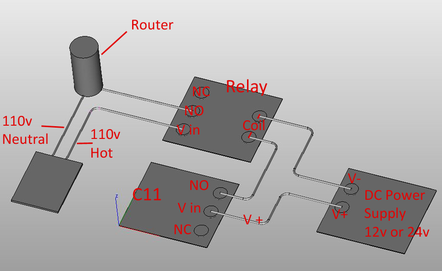
You also need to know the coil voltage and supply power through the C11 Bob to activate the coil and operate the relay. When you buy a relay, you need to be sure you get the right voltage for what you have available. If you've got 12v, then make sure the coil is a 12v coil. You should also find out what the amperage rating of the relay on the C11 is so that you can be sure the coil does not require more than is available or you risk burning out the board. In most cases, relays only take about 200ma or less, so not usually an issue. You also need to know what the current draw of the router is in amps and be sure the relay is rated for it. If not, it is possible that you may need a contactor instead of a relay, and a relay to activate the contactor if the contactor requires more amps to work than the C11 can output (Contactors so similar jobs to relays, but typically offer more current). Assuming the router is small enough to fit on a standard 12vdc coil 120v relay (7-10 amps, check the specs when you buy), you will probably wire it up like the second diagram.
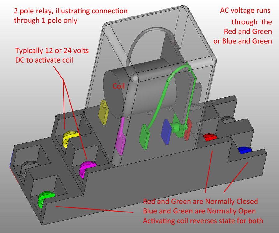
In the diagram of the relay, the grey connections are just the same as the red/green/blue connections on the other side. A two pole relay can handle two signals through, both switched by the same coil simultaneously. You could activate the spindle on one side, and run 12 or 24 volts through the other side of the relay to turn on an LED indicator at your control panel, just as an example. You can also leave it blank, and it won't make any difference. There are also 4 pole relays available which simultaneously activate or deactivate 4 different circuits depending on if they are open or closed. If you use the relay to pass signals, you can use both the N.O. and N.C. outputs to pass a signal to two different destinations. Relays are very useful for a wide range of applications in machinery.
-
12-12-2013, 05:14 PM #14
Community Moderator
- Join Date
- Dec 2003
- Posts
- 24221
Ok mmoe put together one for you, if you prefer SSR relay just substitute the relay for a SSR, two low voltage in, two switched AC out.
For the 12v you can use the 12v from the PC P.S. off of a HD connector etc.
Al.CNC, Mechatronics Integration and Custom Machine Design
“Logic will get you from A to B. Imagination will take you everywhere.”
Albert E.
-
12-12-2013, 10:31 PM #15
Registered
- Join Date
- Mar 2010
- Posts
- 68
Attachment 213100
Ok please dont laugh to hard but what are the relays on the board good for if I got to buy more relays to protect these relays? They say they are rated for / 7A @240VAC / 10A @ 120VAC / 10A 28VDC. I called Automation Electronics and Also CNC4PC but no reply's. I reckon no one hooks up stuff like this. If not I wonder what the relays purpose of being on the board?
-
12-12-2013, 10:58 PM #16
Community Moderator
- Join Date
- Dec 2003
- Posts
- 24221
A couple of reasons for using external relays, one is that if you ever destroy or otherwise burn out the contacts on the internal relays, you will have to either de-solder and replace them or buy another board.
Two, the rating is not always enough for higher powered switching, as in large routers etc, they are fine for turning on a VFD FWD/REV inputs or very low current operations etc.
Al.CNC, Mechatronics Integration and Custom Machine Design
“Logic will get you from A to B. Imagination will take you everywhere.”
Albert E.
-
12-13-2013, 11:24 AM #17
Registered
- Join Date
- Jan 2013
- Posts
- 119
Jeff; You seem to be fixated on trying to use these relays to drive your router.
Al The Man, mmoe and myself would probably wire it a little different way.
We do all seem to agree. that these relays are not rated to drive your router, and
that they need to drive a device with contacts rated to match your router.
You have not indicated how many amps or watts your router draws.
Would you post that information?
Maybe we are all assuming that your router power ratings are higher than they actually are.
Below is another schematic that shows how I would do it. Every component and connection
is what it is and where it is for a reason! I am assuming that when the input pin is high
the NO contacts of the relay are closed. This configuration solves a problem that you don't even
know about yet.
Attachment 213250
-
12-13-2013, 03:58 PM #18
Registered
- Join Date
- Mar 2010
- Posts
- 68
Thanks everyone and I really apprieciate the response and trouble everyone is going through to help me. I like to really understand something before I do it, hence the reason it sound I am am being stubborn. I know very little about circuits so I really do thank every one. My router is a Porter Cable 892 with a soft start 12 amp motor 2-1/4 HP. Later when I save some money I will probally get a spindle and VFD. I will also be running a shop vac that is 5hp 12 amp also. Thanks for the diagram the last one is what I will do because I don't want problems later. I understand all the symbols except the triangle one. I am sorry but could you dumb that down for me a little? Thanks a million, I am getting close.
-
12-13-2013, 04:12 PM #19
Community Moderator
- Join Date
- Dec 2003
- Posts
- 24221
Of course you are at liberty to use what method you want, but I do not see any need what so ever for the 7474 inverter? The input to the SSR is minimal, just a few Milliamps.
Therefore there is no stress placed on the C11 relay at all.
In any case, it is not wise to leave the TTL input floating, it is open to spurious noise pick up etc.
The Opto22 brand of SSR's are rated up to 60amp versions I believe.
Al.CNC, Mechatronics Integration and Custom Machine Design
“Logic will get you from A to B. Imagination will take you everywhere.”
Albert E.
-
12-13-2013, 04:57 PM #20
Registered
- Join Date
- Mar 2010
- Posts
- 68
Wow Al.....I wish I knew what you were talking about. Remember I am super green here. I want to do what is right and what will cause no problems later.


 Reply With Quote
Similar Threads
-
C8-A/C Relay Board Question
By CStevens6 in forum CNC Machine Related ElectronicsReplies: 1Last Post: 03-10-2013, 09:09 PM -
Relay Board
By Darc in forum Controller CardsReplies: 3Last Post: 11-03-2010, 09:23 PM -
Relay for HobbyCNC board
By pilotjunky in forum Hobbycnc (Products)Replies: 1Last Post: 12-24-2008, 07:50 PM -
Correct Relay board for Mach and router
By WilliamD in forum Mach Software (ArtSoft software)Replies: 3Last Post: 04-17-2008, 12:54 AM -
Mach2 & Rutex relay board.
By ynneb in forum Mach Software (ArtSoft software)Replies: 1Last Post: 08-22-2004, 07:50 PM
