


Take the LMS solid column mill for example, other parts of the world it is an SX2 or what not, but with a solid non tilting x2 based mill, is there a reason no one has put a spacer between the base and the column to raise the height. The head does not go all the way down with the vise and tool holders installed so in practical terms raising the flange should not be a problem for at least another few inches it would seem. I have seen all manner of plates used to swap columns and bases. I am unclear why this is not done on this mill with 4 bolt flange. A double sided flange is simple as well.
If the mill has another 2 inches of Z it would be very desirable for that once in a while drilling or what not. Obviously if you want to fly cut at the top of the column there are better options but I can see needing to drill something once in a while or what not. Anyhow adding a 2" spacer seems like not a bad idea and easy to do. It is clear it is a bad idea since it is not done.
Anyone thought of this and realized it is not feasible care to share that reasoning?
Thread: Rigid column X2 mill spacer?
Results 1 to 20 of 81
-
12-15-2013, 06:27 AM #1
 Registered
- Join Date
- Mar 2011
- Posts
- 123
Rigid column X2 mill spacer?
-
12-15-2013, 07:01 AM #2
Member
- Join Date
- Sep 2006
- Posts
- 6463
Hi,....the short answer is if you want to have a lollipop on a longer stick that is what you will get.
The aspect ratio is too large, that is the base area in relation to the height does not make for stability and head nod with those dovetail slides is not the most desirable feature to want when you're going up and down the column.
I suppose next you will want to convert the manual mill to a fully CNC capable model........pigs will fly sooner.
Ian.
-
12-15-2013, 07:30 AM #3
Registered
- Join Date
- Mar 2011
- Posts
- 123
Ok, well it was just a question, not sure i see how it would nod more bolted to a 2" steel plate instead of the base but thanks for clearing that up. The x3 is likely more wobbly yet but I'll take your word for it. You guys would know better than I for sure.
-
12-15-2013, 02:56 PM #4
Member
- Join Date
- Feb 2008
- Posts
- 521
Unless you are increasing the base area of the 2" plate, all you have done is increase the lever acting against the base. Think short stubby Oak tree against tall leggy pine tree - the pine whips around more. Same effect on the milling head. The mod to do would be add the 2" block whilst bolting the whole base to 'say' a 1" plate and adding rigid mounted struts from the column down to the plate - adding turnbuckles would allow for tramming the column and make a pretty rigid assembly! Originally Posted by NewHobby

-
12-15-2013, 04:41 PM #5
Member
- Join Date
- Sep 2006
- Posts
- 6463
Hi, I sympathise with your shortcomings, and if I were using an X2 I'd bolt it to the floor near a solid wall and add two braces from the head to the wall......that will reduce a lot of the vibration that sets up when the cutter shakes the head due to the column being a mite on the thin side.
The head nod symptom is mainly due to having the Z axis gib slack enough to move the head.....if you tighten it up it'll go stick slip as the head drops under gravity.
You could add a counterweight with pulleys etc to pull the head up against the Z axis screw thread so that you are always pushing the head down (the counterweight tries to pull it up)....this prevents the head from dropping when it stick slips etc.
That system is used on horizontal boring mills where the head is always pulled up and the screw always pushes it down.
It works with a pair of cables and pulleys over the top of the column and the counterweight hangs down the back, the same system is used on some surface grinders.
Ian.
-
12-15-2013, 07:47 PM #6
Registered
- Join Date
- Mar 2011
- Posts
- 123
Soo.... are you saying the column is too flimsy or is the mount point at the base too weak?
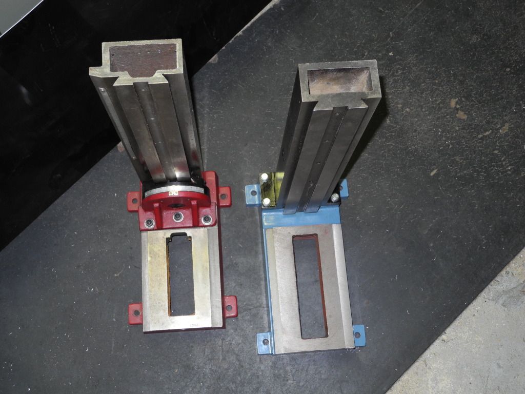
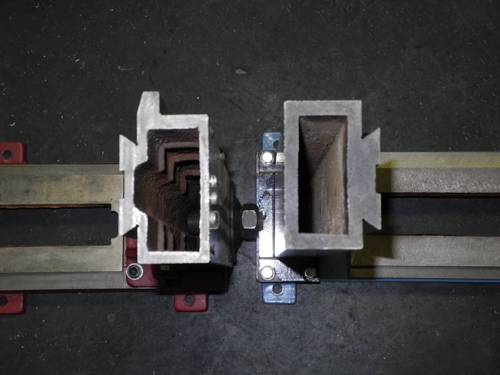
Also to make sure were talking the same thing, I added a pic from a Zone post. The column on the left is the tilting X2 you all know.
One on the right is the SX2 or solid mount column. It is a lot thicker all around and has 4 solid mount points.
You all mean to say that adding a 2" spacer art the bottom and possibly a back plate like many do for the regular X2 will make it statistically significantly worse?
I hear what you guys are saying, on a regular X2 mill, yes I agree, on the SX2, out the gate the column is rigidly mounted and way thicker..... not sure sure it is a horrible idea.
-
12-15-2013, 11:36 PM #7
Member
- Join Date
- Sep 2006
- Posts
- 6463
Hi, I expect when they designed the column section they used finite element analysis and decided , yup, it'll work.....only problem is you now have their design for what it's worth, and any shortcoming due to oversight is in your court, having bought it, and the designers can flood you with figures until doomsday to support their claims which you are unable to do unless you also apply the section, material and column length to a formula and do a similar FEA test.
But you also have to apply the cutter loading and tool holder characteristics to get a figure that makes any sense, and for all intents and purposes the figures won't make sense when you get vibration due to column flexing etc......and now you want to introduce another flex point right at the bottom of the column where the main strength point is?????
If you go to lathe technology, it is a fact that for a boring bar, the stick out length should not exceed 4 times the diam or you'll get flexing which means chatter at the tool point.
The stickout length to the diam ratio is called the aspect ratio.
Well in that case, when all things are equal and you have a hollow column.....what is your aspect ratio?
The column sticking straight up like a pencil is prone to vibration due to resonant frequencies and pure tool pressure.
Having a large piece of metal in the head casting also adds to the lollipop on a thin stick scenario where the stick flexes and will vibrate if you lick the lolly fast enough.....LOL.
Adding a brace like I suggested will stop the column vibrating at resonant frequency but it won't stop deflection under load.
You can only go by the results others have achieved with a similar mill, so do the research before you cut metal.
Ian.
-
12-15-2013, 11:51 PM #8
Member
- Join Date
- Sep 2006
- Posts
- 6463
Hi again, just as a matter of interest, if you mounted the mill on a thick base and then added a piece of heavy section channel iron to the back of the column, welded to the base, to double the size of the column section, that is, making it almost a square box instead of a rectangle, you would effectively have braced the column and added to it's cross sectional area........that is a lot of work, but could pay dividends for such a cheap machine.
I think the brace to the wall is simpler.
Ian.
-
12-16-2013, 01:03 AM #9
Registered
- Join Date
- Mar 2011
- Posts
- 123
I agree, I'd mount the whole mill to 1" steel plate and add a blacking plate and tie it in to the steel base plate along with a spacer. Were I struggle with back bracing in in tramming. Putting a back black brace in is tricky without pulling the column one way or the other, which would make trimming tricky or pull it out of tram.
Something like this

-
12-16-2013, 10:16 AM #10
Registered
- Join Date
- Mar 2006
- Posts
- 23
IMO adding the spacer won't hurt you compared to doing the same cut without a spacer. That's the important part. Taking a cut at the same distance from the table, the moment arm is identical, spacer or no. The spacer will allow you more z for drills, chucks, etc, just don't try milling heavy cuts at the very top or you can expect more chatter. Just because you have the extra z doesn't mean you use it all the time.
In fact, the spacer may well improve the rigidity of the column when cutting within the original z envelope. Why? A length of hollow tube has now been replaced by a solid section. Considering only the possible flexure of the column of course and not bolts or the base itself.
Conclusion: I'd do it if it was my machine. I have the tilting x2 though so I have my own problems.
-
12-16-2013, 03:50 PM #11
Registered
- Join Date
- Apr 2013
- Posts
- 97
I'd go ahead and make one if you don't like the results can just take it out. I don't think it's going to give you any troubles cutting the same height off the bed as without it. Obviously the top 2 inches from your extra travel would definitely be worse
-
12-16-2013, 05:44 PM #12
Registered
- Join Date
- Mar 2011
- Posts
- 123
That is exactly how I see it, at 2 inches above the part I am not 2 inches lower on the column than normal where is is stiffer. I tis is ince in a while frilling somethiente that does not fit. Any of these bench top mills suck cutting at the top of the Z, the spacer is not trying to fix that, itis ,aking it so I can turn a part on the side and drill it once on a bluie moon. Until then it "should" be stonger over all a normal operating ranges in my thought as well. Originally Posted by jdrew1
Dick CNC is right as in that it is easy to reverse if I don't like it.
-
12-16-2013, 05:59 PM #13
Registered
- Join Date
- Aug 2008
- Posts
- 187
yeah sooner or later someone will come along and agree with your preconceived notions and validate your opinion correct or not. why exactly do you think you need 2 more inches of z travel on this little mill? you couldn't find another machine that has the travels you want out of the box?
-
12-16-2013, 06:00 PM #14
Member
- Join Date
- Sep 2006
- Posts
- 6463
Hi, by no stretch of the imagination can you say that the column has more rigidity when you add a spacer at the bottom even if it is a solid chunk etc.
The moment you introduce a joint zone you are subject to just the cross section area of the bolts for the column's integrity.
That is, the column has a cross sectional mass of whatever, taking out the hollow in the middle etc and you are left with the thickness of the 4 walls as the total cross section mass.
Now you are going to bridge the gap between the column base and the spacer, (and the new base plate too), with 4 bolts that have a cross sectional area of approx. 1/20th the column cross section......that is the only strength you have at the interface, and that is where the column will lever against when you are up at the top and doing some drilling that levers the column backwards.
If you do add a spacer you would also be better served by adding a back brace from the base to the top of the column in the form of a large V, where the point of the V is bolted to the back of the column at the very top, and the bottom two legs of the V are bolted to the base plate, spread apart back from the column to give an angle of about 20 deg.
This will give a 3 legged stool effect, with the column being the one leg of the stool.
Ian.
-
12-16-2013, 06:42 PM #15
Registered
- Join Date
- Mar 2011
- Posts
- 123
bjones following that logic to the ultimate absurd conclusion, buying a mill and modifying it means there is a better option for you. There is always a better option. At the end eryone has HAAS Mini mills, any modification means there is a better option. 1/2 the fun is messgin with them and trying stuff just to see though.

Of course, but that's is not exactly what I said or meant, the column won't be stiffer of course not. That is absurd. But if one cuts with the head LOWER on the column then the stiffer it is. We all agree ont hat point assuming the base is reasinable. Raise the column and the head is effectivly lower on the column but the raised amount when cutting. Rais ethe head all teh way up and it will be more flimsy of course.by no stretch of the imagination can you say that the column has more rigidity when you add a spacer at the bottom even if it is a solid chunk etc.
In any event thanks for the fun opinions and feedback!
-
12-16-2013, 07:00 PM #16
Registered
- Join Date
- Aug 2008
- Posts
- 187
um no not everyone needs a haas but it's important to figure out what you need first then get a machine to match, picking one that you plan to have to modify from the start doesn't sound very logical.
-
12-16-2013, 08:07 PM #17
Registered
- Join Date
- Mar 2011
- Posts
- 123
I hear you, it is a valid point and thanks for looking out and providing that perspective. That said, there is always a better option was my point. Not sure it is any less logical than doing a CNC conversion. That is kind of the point of the whole site, modifying mills for some particular reason tha tnot everyone will understand. This site if fuill of mills people buy only to start modifying them. There is some truly weird ingenious stuff out here.
I suppose budget and space play a factor for many including me, more space though. Some jsut liek doign things the hard way ans solving problems. What ever is fine ther eis room for all. That said I don't need to do any of it, I was just asking the question. Same reason a guy climbs a mountain. Becasue it is there. "I wonder if...." Part fo teh human condition I suppose.
Looks like did try it not that that is any evidence other than I am nto the first to ponder it.
LMS 3900 Extended Solid Column

-
12-17-2013, 02:59 AM #18
Registered
- Join Date
- Mar 2006
- Posts
- 23
You bring up a good point Handlewanker, and I've been thinking about this all day now. (the joys of unemployment)
It's been a couple of years since machine design class, but the way I understand it is that since the bolts are preloaded they only "see" a portion of the load applied to the joint. The rest of the load goes to deforming the remaining materials in the joint.
Anyway, I ran a quick FEA in Solidworks to satisfy my curiosity. Two cases: one plain column bolted to a plate. One column bolted through a spacer to the plate (threads not engaged in spacer of course), with the column shortened by the height of the spacer. Identical loads (100lbf) and fixtures. Bolts were simulated in SW, and I believe SW Simulation models them as elastic since it asks for the Young's Modulus. The deflection results are surprising. For those not versed in FEA, the deflection at the tip of the unspaced column is 0.46mm. The deflection at the tip of the spaced column (at the same 12" distance from the table) is 0.19mm. I can't find any mistakes in my setup but I haven't used SW Simulation that many times. It's very possible I'm missing some crucial detail, but there you have it.
Attachment 213984
-
12-17-2013, 03:35 AM #19
Registered
- Join Date
- Mar 2011
- Posts
- 123
Ahhh the magic of solid works, I use bobcad, thanks for checking in jdrew1. That is exactly what I surmised would happen. With a spacer, half way up the column it is indeed stiffer that at the same absolute height with no spacer as one would logically expect. There is less column to flex. Again absolute heights not relative heights.
Cutting at the top of the z is not optimal, if one does that a lot one likely needs a different mill bones is right about that aspect.
But this column would flex less mid stroke than a non blocked version. Yes we all know at the top it would flex more like in a court, I will stipulate that.
-
12-17-2013, 04:13 AM #20
Member
- Join Date
- Oct 2005
- Posts
- 4230
the only true test is to just do it . put a dial on the column without the spacer and pull on the column with a fish scale . Give it 50 lbs of pull and check the flex , then add a spacer and do the same thing . Theory is a great thing but many times it gets in the way of progress
A poet knows no boundary yet he is bound to the boundaries of ones own mind !! ........

 Reply With Quote
Similar Threads
-
IH mill head spacer
By Runner4404spd in forum Charter Oak Automation Support ForumReplies: 23Last Post: 02-08-2009, 05:44 PM -
Mill Column Mods
By digitalmdj in forum Shopmaster/ShoptaskReplies: 8Last Post: 03-30-2008, 02:11 AM -
Knee Mill vs Square Column Mill
By SCzEngrgGroup in forum Bridgeport / Hardinge MillsReplies: 0Last Post: 11-10-2007, 01:27 AM -
Round column mill
By rodzilla in forum Benchtop MachinesReplies: 4Last Post: 08-16-2007, 02:00 AM -
HARBOR FREIGHT small round column mill to a square column conversion.
By motomitch1 in forum Vertical Mill, Lathe Project LogReplies: 25Last Post: 12-01-2005, 05:24 PM
