


Not sure if I am up to it, but this is my latest dream. Still designing but here is the "short block". Stay tuned as thing progress....
Eric
Results 1 to 20 of 206
-
05-27-2006, 01:52 AM #1
 Registered
- Join Date
- Mar 2003
- Posts
- 2139
Another effort, 2 cylinder inline water cooled
I wish it wouldn't crash.
-
05-27-2006, 04:22 AM #2
Registered
- Join Date
- Jan 2005
- Posts
- 746
Any idea's on how many cu. in. it will be.
If it's not nailed down, it's mine.
If I can pry it loose, it's not nailed down.
-
05-27-2006, 05:03 AM #3
Registered
- Join Date
- Apr 2003
- Posts
- 1873
Keep up the good work Eric,
It has been very enjoyable watching you build upon your ideas.
Ken
-
05-27-2006, 05:05 AM #4
Registered
- Join Date
- Mar 2003
- Posts
- 2139
7/8" bore, 7/8" stroke. Computes to just over 1 square inch...
I wish it wouldn't crash.
-
05-28-2006, 01:41 AM #5
Registered
- Join Date
- Mar 2003
- Posts
- 2139
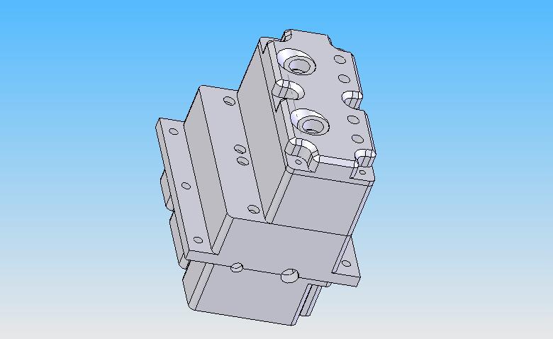
Starting to look like something...
 I wish it wouldn't crash.
-
05-28-2006, 05:07 AM #6
Registered
- Join Date
- Jan 2005
- Posts
- 746
How about making it a Hemi.
If it's not nailed down, it's mine.
If I can pry it loose, it's not nailed down.
-
05-29-2006, 02:16 PM #7
Banned
- Join Date
- May 2006
- Posts
- 138
Nice work Eric. Looks like it'll be a nice engine.
Is the camshaft to be driven by gears, chain or toothed belt?
Keep the pictures coming! How is the design progressing, when do you intend to start machining?
Nick
-
05-29-2006, 04:06 PM #8
Registered
- Join Date
- Mar 2003
- Posts
- 2139
The cam will be gear driven. Gears will be outside the block (no room inside). I will start machining once I feel comfortable with how everything fits (maybe a week or two). I am a beginner at Solidworks so the design is a little slow to progress, also as I go I want to make changes which adds to the problem. At least I am learning.
This design will stretch my abilities in both machining and cnc programming. I hope I am not biting off more than I can chew.
I have no idea how to draw a spring in Solidworks so forgive the lack of valve springs for now.
 I wish it wouldn't crash.
-
05-29-2006, 07:45 PM #9
Registered
- Join Date
- Mar 2003
- Posts
- 2139
Woops. I have a serious interference issue with the crankshaft, con-rods hitting the block.....Crap. Hang on, big changes coming...
I wish it wouldn't crash.
-
05-29-2006, 10:17 PM #10
Registered
- Join Date
- Apr 2005
- Posts
- 281
Been following this with interest and maybe reccomend from looking at your layout. Your oil sump(pan) I presume is what the bottom part is and for clearance you probably should go straight down the side opposite the push rods. This may give you the clearance for the rods and also the crankshaft counter weights.
Just a suggestion and keep it up.
John
-
05-30-2006, 09:33 AM #11
Banned
- Join Date
- May 2006
- Posts
- 138
Yeah now you've mentioned it it does look a bit offset towards the camshaft side. Nevertheless, sure it won't be too hard to sort out at this stage and it's still looking great.
Is solid works a PC based CAD package? What are the tech requirements of the PC to run it?
I could really do with some sort of 3D package, I can use Unigraphics at work but I don't really want to be at work any longer than I have to!
Nick
-
05-30-2006, 01:58 PM #12
Registered
- Join Date
- Apr 2005
- Posts
- 281
On another note with the clearance for the bottom end you may have to go wider at the sump/block. A lot of engines are large in that area for the same reason. Just about impossible to keep it narrow using rods with capscrews to. If you look at a model rc engine or other type(weedwacker/chainsaw) they do not have bolts on the rods. They are full circle on the bottom.
John
-
05-31-2006, 01:26 AM #13
Registered
- Join Date
- Mar 2003
- Posts
- 2139
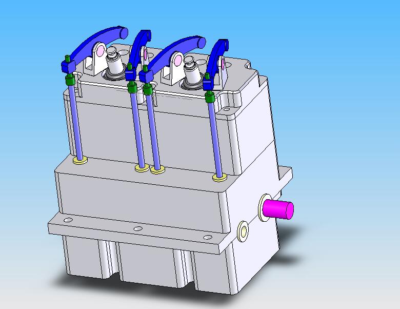
It's gotten fatter but it all fits now....Getting harder to machine too...
 I wish it wouldn't crash.
-
05-31-2006, 01:39 AM #14
Registered
- Join Date
- Mar 2003
- Posts
- 2139
Hey if you want to see the model dynamically, download the free viewer here: http://www.solidworks.com/pages/prog..._register.html Select edrawings viewer only and download and install. Then click on
THIS to see the model and be able to manipulate in in all kinds of cool ways.
EI wish it wouldn't crash.
-
06-02-2006, 12:39 AM #15
Banned
- Join Date
- May 2006
- Posts
- 138
Eric,
I downloaded that e drawings viewer. The engine is looking excellent. I was quite surprised how much you could do with it, hiding components etc. Was also surprised my old laptop could render the graphics, it's a bit slow when rotating but still works.
Couple of questions about the engine now then! What is your intended compression ratio? The combustion chambers look quite large but it's hard to tell really. Guess you'll be aiming for about 6:1?
Do you intend on having a centre crank bearing? I guess it will probably be strong enough without on an engine this size? Will ease manufacture too.
Will there be plenty of room for the water ways, and what about lubrication? Will oil be splashed up there?
1 last thing, the way you have the push rods in those guides, not sure whether that would work well, as the rockers' motion isn't parallel, so maybe you would need cam followers for the pushrods to go into to allow it to move where it wants to.
Appologies if you have already thought of these things, I can see you are in the early stages of design.
I have been on a Unigraphics 3D CAD course but I can't think how to creat springs either!
Keep up the good work and keep us posted, engine is looking great!
Nick
-
06-02-2006, 03:15 AM #16
Registered
- Join Date
- Mar 2004
- Posts
- 106
Really nice work Balsaman

Can't wait to build my first IC engine.... I still dream....
I try to upload a nice spring made in Solidwork so you will have something to start with, but solidworks file extension is not valid for upload.... (chair)
CrazyRonny :cheers:
-
06-02-2006, 03:57 AM #17
Registered
- Join Date
- Mar 2004
- Posts
- 106
I try to make a small tutorial with picture for spring creation in Solidworks.
Begin to sketch a circle for the Helix

Then make the Helix

Next sketch the circle that will follow the helix

And now make the spring with the Base-Sweep tool

And you can be fancy and make a nice spring end .....

I wish it will help
And if it take to much space on your thread... tell me and I will remove it...
CrazyRonny :cheers:
-
06-02-2006, 12:14 PM #18
Registered
- Join Date
- Mar 2003
- Posts
- 2139
Perfect. Thanks very much.
EricI wish it wouldn't crash.
-
06-02-2006, 01:01 PM #19
Registered
- Join Date
- Mar 2003
- Posts
- 2139
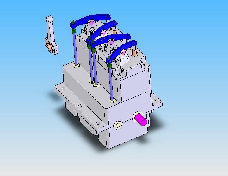
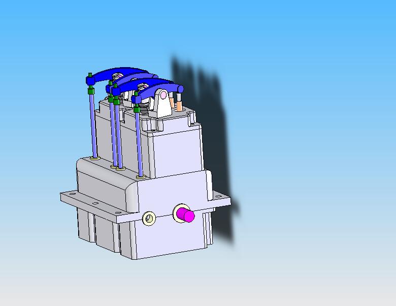
It's 6:1. The steel sleeves are not in there yet if you are wondering why the cylinder is larger than the piston.... Originally Posted by nick.gilling
I thought about a center bearing. May happen yet, not sure if it's needed. Originally Posted by nick.gilling
I hope to splash it up there. Maybe a spoon or scoop on the rods. Originally Posted by nick.gilling
The interface between the lifter rods and rockers will be quite loose. The green part is a socket head cap screw with the socket drilled out round. I may extend the bushings in the case down towards the cam for more support there. The cam lift will be somewhat small. Originally Posted by nick.gilling
Originally Posted by nick.gilling
I wish it wouldn't crash.
-
06-02-2006, 01:44 PM #20
Banned
- Join Date
- May 2006
- Posts
- 138
Good stuff.
Looks like you've thought of everything!
Can't wait to see it start coming together.

 Reply With Quote