


Stephen,Originally Posted by scubasteve_911

I agree 100% on that. A few bucks for external ADC is not that bad for small volumes, considering the performance advantages. Conversion rate is not the most important spec for the motor control purpose, as the even fastest conversion needs to be done only once per PWM period. Linearity and dynamical specifications are more important. For example, Microchip dsPIC30F3010 has INL and DNL spec of ±1 LSB, compare that to National's ADC128S102, which has INL and DNL spec of ±0.5 LSB MAX. Not to mention that NXP LPC2119/2129 has ±2 LSB INL and ±1 LSB DNL. NXP States that maximum absolute error of the ADC is ±4 LSB, which means that you get only 8 correct bits out of 10 (which is quite typical figure).
An ADC is one of the most difficult mixed-signal IC designs to get right, and require process optimized for the purpose.
Regards,
Janne
Thread: building FPGA motion controller
Results 61 to 80 of 90
-
08-14-2007, 09:33 PM #61
 Registered
- Join Date
- Jul 2007
- Posts
- 10
-
08-18-2007, 05:51 AM #62
Registered
- Join Date
- Jan 2007
- Posts
- 65
Janne,
You must be an experienced electrical engineer! Great to have someone with your talent involved in the forum. I'm finished my electrical engineering degree next year, but have always been tinkering and designing PCBs as a hobby.
Can you give me any advice for learning VHDL? Like, a good book or website? I have done quite a bit of programming in the past, so hopefully it isn't a huge transition. I know M8C assembly, C, and matlab languages fairly fluently.
I plan on creating some VHDL interfacing logic for some converters in the near future for a linear axis. My plan is to develop a linear motor and a precision encoding device that will interface with a custom PCB loaded with a Spartan III FPGA. It will accept both RS232 and step/dir signals for the axis. This is for my degree project due next May, so I have quite a bit of work to do!
Steve
-
08-18-2007, 10:29 AM #63
Registered
- Join Date
- Jul 2007
- Posts
- 10
Thanks Steve, I have been a "pro" about 7 years now, but I think it really is a continuous learning process
 I can't personally recommend any specific book, since I learned VHDL pretty much by trial-and-error procedure and studying other peoples codes. Perhaps not so good approach. At work, we have this book.
Grasping the VHDL is not so much about the syntax, as it has strong similarities with ADA. If you have no problem with the languages you mention, there should be little problems. VHDL has very strict type checking, which can be sometimes frustrating if you have used to C flexibility.
IMO the most difficult thing is to learn how the particular structure will synthesize. Sometimes this leads to errors which are difficult to find and sometimes correct behaviour is done with rather counterintuitive structure. Remember, typical FPGA "logic element" will contain a LUT combined with a D-flip flop. This means that when coding for example a state machine, signal updates happen after you exit a particular state, not when you enter one. This is because the LUT will contain all the logic contained in each state, and DFF wil latch this output when the next active edge will happen.
You'll find that it is much easier to do things in parallel instead of sequential execution. Sequential execution requires you to code some sort of state machne or counter. All syntactically legal structures won't be synthesizable at all (for example pin_a <= '1'; pin_a <='0' after 10 ns; won't yield to 10 ns pulse when synthesized, instead the pin_a will stay in 0-state), but you can use them in test benches.
Regards,
Janne
-
08-19-2007, 08:37 AM #64
Registered
- Join Date
- Jan 2007
- Posts
- 65
Janne,
Thanks very much for your advice, I hope to be able to learn through a similar process to be able to write what I need. I have done some research on VHDL and it seems fairly transparent to the actual target structure, which makes it easy to see why understanding synthesis is the path to achieving the right results, the first time.
Of course, I would love to take advantage of the parallel processing ability. I have done work in the past with FPGAs, but without VHDL, and it worked nearly in real-time due to high-speed parallel structure.
I will be sure to post my progress when I start trying to iron out the rather large endeavour of an engineering project. Thanks for your comments!
Steve
-
08-19-2007, 02:59 PM #65
Registered
- Join Date
- Nov 2005
- Posts
- 72
Today I made code comparison of Quadrature encoder decoder between my code and jahonen suplied code.
I made litle modification in my and jahonen code so that both code performed one operations quadrature decoding+ direction decoding+ 32bit up/down counting (all other functionality was removed).
here are results after compilation using Quartus 7.1
my code takes 47 Logic cels but johanen 66 cels so I have 19 cel more efficient code, I think this diference is becouse jahanen for Quad decoding and direction decoding used signle state machine and compiler created state machine that consumes 33 cels, but I created this logic by process statements and used partial design (you can see that for each channel I have its own decoder + one direction decoder for 2 channels and in top level file I just created 32bit up/down counter (consumes 33cels) and stitched all files together so in the end I have 19 cell more efficient decoder, just because of different coding style,
but I think that my code needs one more clock cycle compared to jahonens code because of separate process design (you can think of it like pipelining
but if we compare code complexity then my code is much more complex then jahanens.
-
08-22-2007, 10:21 PM #66
Registered
- Join Date
- Jan 2007
- Posts
- 65
Episs,
Would you mind posting your VHDL for us to look at? I wouldn't mind checking it out
Steve
-
08-23-2007, 11:19 AM #67
Registered
- Join Date
- Nov 2005
- Posts
- 72
Ok here is this code in 3 separate files firs 2 files I didn't change because they are main building blocks.
firs file is Edge decoder witch senses both rising,falling edges and generate impulse caled STP (step) and this block decodes just one encoder channel input, maby by combining them together it could be possible to save additional cells ! this edge decoder consumes 4 cells.
second is direction decoder it takes 6 cells:Code:LIBRARY ieee; USE ieee.std_logic_1164.all; -- Entity Declaration ENTITY EDge_decoder IS -- {{ALTERA_IO_BEGIN}} DO NOT REMOVE THIS LINE! PORT ( clock : IN STD_LOGIC; ENC : IN STD_LOGIC; STP : OUT STD_LOGIC ); -- {{ALTERA_IO_END}} DO NOT REMOVE THIS LINE! END EDge_decoder; ARCHITECTURE EDge_decoder_architecture OF EDge_decoder IS signal E1_A :std_logic; signal E1_IRQ :std_Logic; signal BR :std_logic; signal BF :std_logic; Signal IRQ1_R : std_logic; Signal IRQ1_F : std_logic; BEGIN E1_A <= ENC; process(clock) begin if rising_edge(clock) then IF BF ='0' then BR <='1'; end if; if BR ='0' then BF <= '1'; end if; if BF ='1' then if E1_A ='1' then BF <='0'; BR <='1'; IRQ1_R <= '1'; end if; else irQ1_R <= '0'; end if; IF BR ='1' then if E1_A ='0' then BR <='0'; BF <='1'; IRQ1_F <= '1'; end if; else IRQ1_F <='0'; end if; end if; end process; STP <= IRQ1_F xor IRQ1_R; END EDge_decoder_architecture;
and then we have top-level file which combine all together and creates 32bit up down counter.Code:LIBRARY ieee; USE ieee.std_logic_1164.all; -- Entity Declaration ENTITY ENC_DIR2 IS -- {{ALTERA_IO_BEGIN}} DO NOT REMOVE THIS LINE! PORT ( CX : IN STD_LOGIC; clock : IN STD_LOGIC; D_A : IN STD_LOGIC; D_B : IN STD_LOGIC; DIR : OUT STD_LOGIC; AOUT : OUT STD_LOGIC; BOUT : OUT STD_LOGIC; COUT : OUT STD_LOGIC ); -- {{ALTERA_IO_END}} DO NOT REMOVE THIS LINE! END ENC_DIR2; -- Architecture Body ARCHITECTURE ENC_DIR2_architecture OF ENC_DIR2 IS signal A,AA1,B,BB1,izeja,izeja1,izeja2 : std_logic; BEGIN process(clock) begin if rising_edge(clock) then A <= D_A; end if; end process; process(clock,CX) begin IF CX ='1' then if rising_edge(clock) then B <= D_B; end if; end if; end process; BB1 <= NOT B; COUT <= izeja1; BOUT <= izeja2; AOUT <= izeja; Virz:process(A,clock) variable index1 : std_logic; begin if rising_edge(clock) then if A='1' then if index1 ='1' then izeja1 <= BB1; index1 := '0'; end if; else index1 := '1'; end if; end if; end process; Virz2 :process(A,clock) variable index1 : std_logic; begin if rising_edge(clock) then if A='0' then if index1 = '1' then izeja2 <= BB1; index1 := '0'; end if; else index1 :='1'; end if; end if; end process; process(clock) begin if A ='1' then izeja <= izeja1; else izeja <= izeja2; end if; end process; process(clock) begin if rising_edge(clock) then if CX ='1' then DIR <= A xor izeja; end if; end if; end process; END ENC_DIR2_architecture;
and here is little modified Jahonen code. I commented out all code that I didn't used leaving just pure Quad decoder + up down counter for comparisonCode:LIBRARY ieee; USE ieee.std_logic_1164.all; use IEEE.STD_LOGIC_ARITH.ALL; use IEEE.STD_LOGIC_UNSIGNED.ALL; -- Entity Declaration ENTITY Encoder_step_counter IS -- {{ALTERA_IO_BEGIN}} DO NOT REMOVE THIS LINE! PORT ( clock : IN STD_LOGIC; A,B : IN STD_LOGIC; count : OUT std_logic_vector( 31 downto 0) ); -- {{ALTERA_IO_END}} DO NOT REMOVE THIS LINE! END Encoder_step_counter; ARCHITECTURE Encoder_step_counter_architecture OF Encoder_step_counter IS signal A1,B1,AB,DIR : std_logic; signal counter : std_logic_vector(31 downto 0); Component EDge_decoder IS PORT ( clock : IN STD_LOGIC; ENC : IN STD_LOGIC; STP : OUT STD_LOGIC ); end component; component ENC_DIR2 IS PORT ( CX : IN STD_LOGIC; clock : IN STD_LOGIC; D_A : IN STD_LOGIC; D_B : IN STD_LOGIC; DIR : OUT STD_LOGIC ); end component; BEGIN A_chanel : EDge_decoder PORT MAP( clock=>clock, ENC =>A, STP => A1); B_chanel : EDge_decoder PORT MAP( clock =>clock, ENC => B, STP => B1); AB <= A1 xor B1; Direction : ENC_DIR2 Port map( CX => AB, clock => clock, D_A=> A, D_B=> B, DIR=> DIR); -- the main code starts here process(clock) begin if rising_edge(clock) then if AB ='1' then if DIR ='1' then counter <= counter +1; else Counter <= counter -1; end if; end if; end if; end process; count <= counter; END Encoder_step_counter_architecture;
ass you can see all this Quad decoder+ counter is coded in one big Case statement called "currstate" and placed in one process statement thats why it executes in one clock cycle (compared to 2 clocks in my design) but consumes twice as much as my code (I mean quad_decoder+ direction not 32bit up down counter)Code:LIBRARY ieee; USE ieee.std_logic_1164.all; USE ieee.numeric_std.all; entity CNCzone_kods is port ( clk : in std_logic; dout : out unsigned(31 downto 0); -- din : in unsigned(31 downto 0) := (others => '0'); cha_in : in std_logic; chb_in : in std_logic; cha_filtered_T,cha_T : out std_logic ); -- load : in std_logic); end CNCzone_kods; architecture JTA_design of CNCzone_kods is -- Input synchronizer component isync is port ( sin : in std_logic; sout : out std_logic; clk : in std_logic); end component isync; -- Digital filter component dfilter is port ( clk : in std_logic; sin : in std_logic; sout : out std_logic; sample : in std_logic ); end component dfilter; signal qeposcnt : unsigned(31 downto 0); signal cha : std_logic; signal chb : std_logic; signal cha_filtered : std_logic; signal chb_filtered : std_logic; signal cha_rise : std_logic; signal cha_fall : std_logic; signal chb_rise : std_logic; signal chb_fall : std_logic; signal inc_trig : std_logic; signal dec_trig : std_logic; signal currstate : std_logic_vector(1 downto 0); signal samplecounter : integer range 0 to 255; signal do_sample : std_logic; --signal SAMPLING_INTERVAL : integer range 0 to 255:= 4; begin CHASYNC: isync port map(sin=>cha_in, sout=>cha, clk=>clk); CHBSYNC: isync port map(sin=>chb_in, sout=>chb, clk=>clk); CHAFILT: dfilter port map(sin=>cha, sout=>cha_filtered, clk=>clk, sample=>do_sample); CHBFILT: dfilter port map(sin=>chb, sout=>chb_filtered, clk=>clk, sample=>do_sample); cha_T <=cha; cha_filtered_T<=cha_filtered; -- -- Quadrature pulse decoder -- -- The definition of direction is as follows: -- -- "When the codewheel rotates in the counterclockwise direction (as viewed from the -- encoder end of the motor), channel A will lead channel B. If the codewheel rotates -- in the clockwise direction, channel B will lead channel A." -- -- Clockwise direction increments counter and counterclockwise decrements, respectively. -- -- 32 bit position counter state machine -- process(clk,cha_filtered, chb_filtered) variable newstate : std_logic_vector(1 downto 0); begin newstate := cha_filtered & chb_filtered; if rising_edge(clk) then if do_sample = '1' then case currstate is when "00" => if newstate = b"01" then qeposcnt <= qeposcnt + 1; elsif newstate = b"10" then qeposcnt <= qeposcnt - 1; end if; when "01" => if newstate = b"11" then qeposcnt <= qeposcnt + 1; elsif newstate = b"00" then qeposcnt <= qeposcnt - 1; end if; when "11" => if newstate = b"10" then qeposcnt <= qeposcnt + 1; elsif newstate = b"01" then qeposcnt <= qeposcnt - 1; end if; when "10" => if newstate = b"00" then qeposcnt <= qeposcnt + 1; elsif newstate = b"11" then qeposcnt <= qeposcnt - 1; end if; end case; currstate <= (cha_filtered & chb_filtered); end if; -- if load='1' then -- qeposcnt <= din; -- end if; dout <= qeposcnt; end if; end process; do_sample <= '1'; -- add by me -- --process(clk) --begin -- -- if rising_edge(clk) then -- do_sample <= '0'; -- if samplecounter = SAMPLING_INTERVAL then -- do_sample <= '1'; -- samplecounter <= 0; -- else -- samplecounter <= samplecounter + 1; -- end if; -- end if; --end process; end;
-
08-31-2007, 08:51 AM #68
Registered
- Join Date
- Jan 2007
- Posts
- 65
Good stuff Episs,
I can't really comment on the code, since I don't really understand it yet. Fortunately, I get to be forced into learning VHDL this semester
SteveSteve
"Drink your school, stay in drugs, and don't do milk!"
-
09-05-2007, 11:41 PM #69
Registered
- Join Date
- Sep 2004
- Posts
- 1207
Field oriented control seems to fit quite nicely to steppers. I have implemented one. Originally Posted by jahonen
See: http://video.google.com/videoplay?do...16533290115886
In the video the stepper is running in open loop. Servo-like closed loop requires some more work.
-
09-07-2007, 04:45 PM #70
Registered
- Join Date
- Jul 2007
- Posts
- 10
Looks indeed very nice. It is certainly no surprise that it works so well, since the current controller sees no AC, but DC-currents, thus the dynamics is greatly enhanced. From the controller viewpoint, it is just like current controlling separately magnetized DC-machine. Originally Posted by Xerxes
How did you connect the bipolar stepper to the 3-phase output? I guess that you connected the motor coil other ends together and then connected this to the "unused" 3rd phase of the bridge? Remaining ends then connect to the two phase outputs of the bridge.Then the 3rd phase is just set to 50% duty cycle to provide the mid-point zero voltage for the coils. That reduces usable voltage in half, but I think that there is still plenty of reserve.
Regards,
Janne
-
09-07-2007, 05:05 PM #71
Registered
- Join Date
- Sep 2004
- Posts
- 1207
Yep, that is how I did it. However, 3rd phase doesn't have to be fixed to 50% but can be driven sinusoidally to get more voltage swing. In optimal case the output voltage would be 70% of input voltage. Originally Posted by jahonen
-
09-10-2007, 07:16 PM #72
Registered
- Join Date
- Nov 2005
- Posts
- 72
this is my last modified stepper driver board I added opamp TL084 and comparator LM339 + 74Hc595 which I used for 4bit DAC (to use fewer fpga pins)
[IMGW]http://content1-foto.inbox.lv/albums45024113/epps/Elektronika/Driver-L298-DAC-Opamp.jpg[/IMGW]
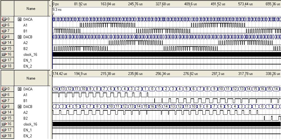
and here is Logic test code which I created in past few days it is just for testing purpose and to see if motor will work in microsteping mode.
[IMGW]http://content1-foto.inbox.lv/albums45359439/epps/Elektronika/microstep-4bitDAC-simulation.jpg[/IMGW]
all this month I was thinking about analog to digital conversion, currently I have comparator and DAC but it seams that this solution in not so good as I was thinking at the beginning, so I started to think about some multi channel ADC converter board, and I ended up that I need some 16 ADC channels for 4 stepper drivers and for 4 optical encoder sin encoders, and I found cheap ADC08060 4$ ADC with speed of 60msps and to get lot of channels will use sn74lv4051a MUX 1:8 and few op amps , I chose so high speed ADC because of small price difference for example cheapest 15Msps cost 3$ and all other lower speed converters are about 2-3$ so why not to buy 60mips + I could use it as oscilloscope If I will make 2 boards one for motor controll other for osciloscope )
-
09-10-2007, 07:20 PM #73
Registered
- Join Date
- Nov 2005
- Posts
- 72
this is my last modified stepper driver board I added opamp TL084 and comparator LM339 + 74Hc595 which I used for 4bit DAC (to use fewer fpga pins)
http://content1-foto.inbox.lv/albums...-DAC-Opamp.jpg
and here is Logic test code which I created in past few days it is just for testing purpose and to see if motor will work in microsteping mode.
all this month I was thinking about analog to digital conversion, currently I have comparator and DAC but it seams that this solution in not so good as I was thinking at the beginning, so I started to think about some multi channel ADC converter board, and I ended up that I need some 16 ADC channels for 4 stepper drivers and for 4 optical encoder sin encoders, and I found cheap ADC08060 4$ ADC with speed of 60msps and to get lot of channels will use sn74lv4051a MUX 1:8 and few op amps , I chose so high speed ADC because of small price difference for example cheapest 15Msps cost 3$ and all other lower speed converters are about 2-3$ so why not to buy 60mips + I could use it as oscilloscope If I will make 2 boards one for motor controll other for osciloscope )
-
10-13-2007, 02:15 PM #74
Registered
- Join Date
- Nov 2005
- Posts
- 72
Past few weeks I started to make software for motion controller(fpga board) that will send information to fpga board.
main tasks that software performs are:
1. G-code instruction read (currently Feed rate(F),+G01 instruction) :
2. calculate 3Axis speed,position, acceleration,deceleration for G01 linear interpolation instruction.(have code)
3. pack all Axis motion data to HEX file. (don't have code)
4, send information by Com port. (have code)
here is picture of current software window and also second window that I used for debugging where can see how software calculate acceleration, position, values for each AXIS reading 2 G-code instructions.
1 window (100) is numbers of steps in one mm
2 is feedrate (0)
3. is acceleration (3) mm/s^2
when software will send thees instruction to Fpga (or fpga board flash memory) fpga will start to generate Step/dir signals by calculating each step speed.
Firs Idea was to send to fpga all G-code instructions directly, and then fpga would need to calculate all axiss speed, acceleration another values to generate step signal, and then I started to think how far computer can make G-code instruction decoding and speed position precalculations to reasonable information amount (~5-20 bytes) for one instruction and this limit for linear interpolation was calculation off acceleration,deceleration,+ position, and NEXt level of calculation is one step speed and imagine if you have to move 1milion of steps (in some 1/8 of 1/32 microstepping mode) in constant acceleration then you will have to send 1M instructions to board and to store such enormous amount of data it would require few GB flash memory just to store some 1M step data that could execute in few seconds so it is not reasonable to make step calculations in PC and it must be done in motion controller for step/dir generation and this is what I am making right now
As I am still beginner in C# language then i think I could share my code making it open source but I will post some code later when i will finish hex file generation code and will connect it with "Com port sending" code to send data to board. + make some debbuging.
-
10-18-2007, 09:27 PM #75
Registered
- Join Date
- May 2007
- Posts
- 106
Hi Episs,your project seems interesting!
I am currently deseigning a servo controller on a dsPIC (during my rares free times ) and I have also been looking for making a G.C -> step dir gen, but It's rater more complex and tricky on a dsPIC :s
It's also my goal making my controller open source, so I think you're going the right way
Now some question^^
-Target steps/s?
-Nomber of axis?
-board price range?
-availability of the FPGA?
-Do you intend having a batch of pcb made by a pro and sell them?
Thanks for reading (and answering^^), and good luck!
-
10-21-2007, 06:19 PM #76
Registered
- Join Date
- Nov 2005
- Posts
- 72
I finished missing code part for information sending by RS232 (COM port) to board and added additional Items including new Text window were you can see data that software will send (each byte is displayed in decimal numbers) + SEND button for data sending.
I think that 1 part is completed and I will start to think about instruction decoder and step/dir signal generator for linear interpolation and about new PCB because I just ordered newest cyclone III fpga form digikey and they are in BGA256 package so my plan is to make new general purpose (ultra small) main board, just with all necessary things to run fpga
like: fast parallel 16Mb configuration flash with MAX3000 for configuration and 1,3Mhz DC-DC regulators.
board will be general purpose because this board will be 4 layer and it will be expensive thats why it is so important to make it as small as possible and to save some money I will order about 50 PCB's and will solder firs ordered 3 Fpgas and if they will work I will sell rest of PCB's with soldered fpga (becouse it is not so simple to solder bga chip.
Also I will make additional add on boards (cheap 2 layer) for additional component that don't require 4 layers and ultra small drilling holes (that are very expensive!)
So it will take time to make new cyclone III developing platform.
So I have lot of work to do.
-Target steps/s -> it would be great to get some 1Mega step/s but at beginning when I will make this step generation software in NIos II processor it could be some 100K steps/s and later will see how high step rate is possible (using some hardware acceleratorsNow some question^^
-Target steps/s?
-Nomber of axis?
-board price range?
-availability of the FPGA?
-Do you intend having a batch of pcb made by a pro and sell them?
-number of axis -> now there will be 3 axis but there are no limits because it is fpga - if need more power then simply take Larger logic density FPGA)
-board price range? -> main fpga board could be about 100$ price range, and add on boards with all connections (price is unknown)
-availability of the FPGA?-> Fpga's will be available all time and logic codes are portable to any fpga with little modifications but problem starts with embedded processor cores like nios II it is not portable to other fpga vendor chip, and newest cyclone III chip is cheapest logic FPGA chips that is available today.
-Do you intend having a batch of pcb made by a pro and sell them?
if i will sell Cyclone III board in BGA256 package then definitely they will be soldered by pro, about Add on boards currently I don't know !
-
10-21-2007, 08:48 PM #77
Registered
- Join Date
- Sep 2004
- Posts
- 1207
Are you planning to process G-code in FPGA? I think you'll run into problems with the complexity of this especially if you want to do some high performance contouring. It's better to pre-process G-gode on PC as far as possible so only simple realtime task is left on hardware.
-
10-22-2007, 08:35 PM #78
Registered
- Join Date
- May 2007
- Posts
- 106
256BGA, 4L board woah, serious work to go here!
but in the 100$ range there is plenty FPGA boards with up to 1000K gates (on a spartan chip I think) USB2, ethernet, plenty RAM etc.
is the Cyclone III worth making a board?
-
10-23-2007, 02:06 PM #79
Registered
- Join Date
- Nov 2005
- Posts
- 72
Not all G-code but pre-processed code to speed,acceleration position command level that my software (EpiCNC) is generating (supported G01 instruction Originally Posted by Xerxes
) and then rest of calculations will be done in fpga.
When I will post EpiCNC software C# code you will see that there are lot of calculations that is done to get those speed,acceleration,position values, and as i already told earlier that this is margin of possible pre-calculation on PC if you go to next calculation lever (calculating each step speed) then you will get enormous amount of data that you will need to send to external hardware in very very high data rates.
I searched in this forum topics about motion controller building and there was few where also was discussed this data sending problem and there are 2 choices you can send pre-calculated each step data (like step signal) or just send speed acceleration+position change commands using this method you can save all commands in some few Mb Flash memory and then execute them in real time + you don't need anymore PC! it is just for executable code generation.
Definitely yes and all parts (without PCB) will cost less than making board for cyclone II for example as my previous self made board it coasted more than this will (exept PCB) and this price reduction is on configuration memory previous cyclone II cheapest config.memory was EPCS4 price 13$, but cyclone III will configure with parallel flash +max3000 total price 5$ and it will configure some 20x faster than with EPCs4 thanks to FPP(Fast PasiveParallel mode) that wasn't in cyclone II generation fpga's, so we get much faster configuration Max.150ms (depends on file size) and 20% cheaper logic + aditiona features that wasn't in previous generation fpga +is the Cyclone III worth making a board?
new cyclone III chip support vertical migration in BGA256 package from smallest Ep2C5 (5K LE) to EP3C25 (25K LE) so it will be possible to solder 4 different density Fpga.
-
01-07-2008, 09:00 PM #80
Registered
- Join Date
- Nov 2007
- Posts
- 277
Having read the entire thread I can say there is a lot of useful stuff going on with your project Episs. I would only say that as a first step I would try interfacing with emc2 and have emc2 do all the g-code interpreting and write emc hal modules to send the commands to your board in whatever format you choose. I.e. Do all the real-time stuff on your board and emc2 hal is just giving the position/speed commands. The emc2 hal modules seem pretty simple.
Later you can impliment an on-board g-code interpreter too if you have the resources. Emc2 has good computation and flow control statements too that are really useful.
For example, I just finished making a gcode program to make protective bellows that is fully parametized. You can specify in variables, the bellow width, number of ribs, distance between ribs, rib angles, etc, and it adjusts. I plan on rewriting the code to cut a mould for making the bellows tonight.
However, I also was kicking emc2 a little because it didnt have a code to rotate the cordinate system. When I implemented the draw codes to draw the right side of the bellows I wanted to rotate the coord system 180 degrees and have it draw the left side going down. Emc2 only has coord system offset. Maybe there is a way but I couldnt find it. I ended up adding a subroutine parameter that is either +1 or -1 and multiplying all the draw code X/Y values by it, thus allowing me to mirror the drawing for that subroutine. My point is that when your gcode interpreter doesnt support a function...it sux!!!
Also, I have tried to use opencores.org code before. I have a lot of problems integrating a lot of the modules I tried, especially the processor cores, I think I tried them all. Many still had bugs in them. The PCI module seemed pretty solid tho, but I never synthesized it.
I even created my own core, and built an assembler using flex and yacc for it. But it's probably pretty useless overall, mostly just a learning experience and was intended to teach others how to make a core from the ground up using verilog. I started a very simple processor and modified it in each chapter. I use ModelSim to simulate my designs with a testbench --- definately learn how to do this with your HDL! Writing testbenches are usually pretty easy because the simulator provides lots of non-synthesizable grammer for this purpose.

 Reply With Quote