Well, up until a few months ago, I would have said that I'd probably never build an oscillating-cylinder steam engine. That was before I saw the little Cracker locomotive win April's Project Of The Month over at the Home Model Engine Machinist forum.
The winner was a guy that goes by the board name of "Shred", and his write-up and photos of this little 16mm-scale (G Scale Locomotives runnng on O-Gauge track, representing 2-foot gauge on the prototypes) were more than enough to convince me I needed to build it.
The plans are available for free in several places online, ( http://home.iae.nl/users/summer/16mm...ms/Cracker.htm ) and before long I had printed them out and was planning to build a PAIR of these little utility engines.
Here's my progress so far.
The first thing I had to do was come up with the gears, as the pitch diameter would set the axle and crankshaft spacing. I followed Shred's advice, and used RC pinion gears from Robinson Racing, as I've used their products many times in my younger days.
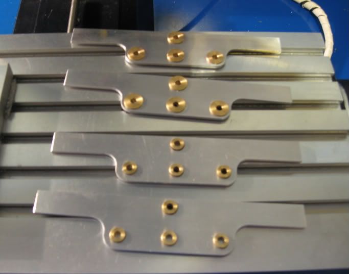
Cutting out the side frames was simple enough, and I decided to build TWO locomotives, one for myself, and one for my dad, who's fuelled my interest in all-things-mechanical since I was a wee lad.
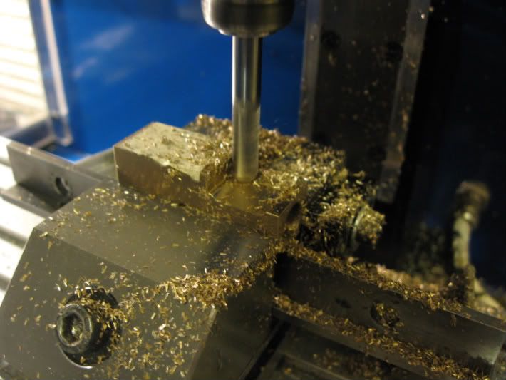
Here's the first frame side plate being cut out on my little Sherline mill.
This is too easy, so far.The loco frames are 10mm longer, 5mm added to each end, to make room for a slightly longer boiler, and more room on the footplate as well. Originally, I was going to add all 10mm to one end, and move the fuel tank under the footplate and between the frame rails, as I've read elsewhere online, but decided against it, at least for THIS build. ;D
I turned two sets of bushings from bearing bronze, again diverting from the plans, and making all 8 bushings to the same dimensions.
Here they are pressed into place in the frame sides.
Thread: Cracker/Cricket Locomotive Build
Results 1 to 20 of 35
-
06-16-2009, 12:19 AM #1
 Registered
- Join Date
- Mar 2006
- Posts
- 474
Cracker/Cricket Locomotive Build
-
06-16-2009, 12:23 AM #2
Registered
- Join Date
- Mar 2006
- Posts
- 474
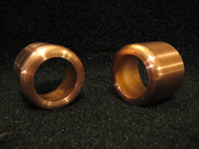
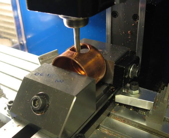
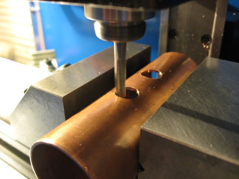
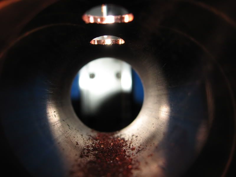
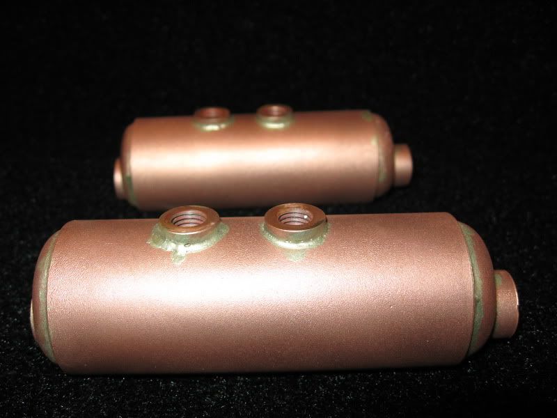
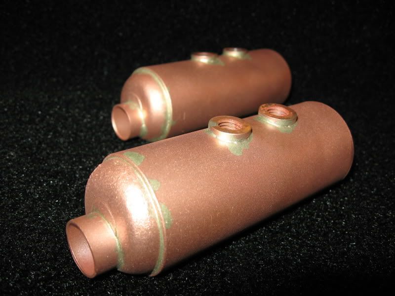
The first of the boiler parts I made for these little locomotives were the end caps that will be silver-soldered into each end of the boilers.
These were made from a slice of the boiler tubing stock, annealed and tapped down over a mandrel I turned in the lathe.
When I made my first set the radius I used was way too big...but at least it'll add extra water capacity. I'll use the big ends for the boiler backheads, but I turned a smaller radius on my mandrel, and made a second set.
Sorry for the blurry photo, the rest will be better. ;D
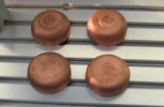
After this photo, all four end caps were drilled for the flue pipe that passes through the boilers, and set aside until later.
-
06-16-2009, 12:27 AM #3
Registered
- Join Date
- Mar 2006
- Posts
- 474
The wheels were fun, so I made an extra set...which will either be used on a THIRD loco, or some rolling stock.
I enjoyed cutting the back flange and tire angles; by setting the tool to cut one angle, and the compound slide to move along the other, these were quick and easy, taking about 2 hours to saw and turn them all.
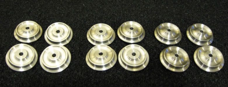
I added a .200" boss to the back side,which wasn't on the plans, so I could use 4-40 setscrews to secure them to the axle. The only place I want to use Locktite on these locos is between the crank throw and the crankshaft.
The frame end beams were easy millwork, and mostly featureless for this photo, missing a few holes.
-
06-16-2009, 12:30 AM #4
Registered
- Join Date
- Mar 2006
- Posts
- 474
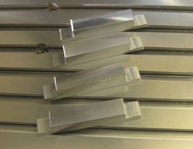
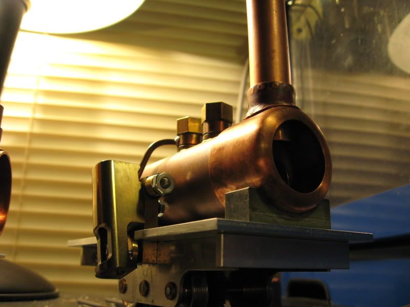
For the smokeboxes, the plans call for a split section of tubing, but I decided that using a pipe cap, with it's radius, would help give the Cracker a smaller, yard-loco appearance.
Here are both pipe caps, with a hole in one end for the smokebox doors.
Right now, they look more like engine cowlings for a radial. ;D
After more consideration, one of the two locomotives may not use this style smokebox... but I'll make that decision in a few more days.
These little "Crackers" have gotten me hooked on live steam locomotives after 40 years of playing with trains.
-
06-16-2009, 12:32 AM #5
Registered
- Join Date
- Mar 2006
- Posts
- 474
The pistons were easy enough, but I made them .375" instead of the plan's .3149"... I couldn't resist making the engine bigger on this little single-cylinder.
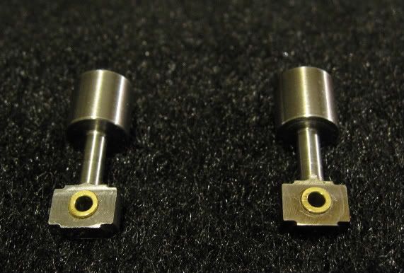
I guess I should add some oil grooves before I call them done.
-
06-16-2009, 12:34 AM #6
Registered
- Join Date
- Mar 2006
- Posts
- 474
My newest progress is a few more pieces;
The boiler bushings, made from Phosphur Bronze...I made them all the same size instead of the plan's 10mm/8mm, tapping them all 5/16-24.
Cylinders for both machines... they're a bit bulky compared to some of the other Crackers I've seen. As I mentioned earlier, with the piston photo, I've enlarged the bore from the plan's .3125" up to .375". I just couldn't help myself.
I wanted plenty of material at the contact face for future lapping, both of these locos are going to be runners, I'm planning for wear. I added brass bushings to the big-end of the pistons for the same reason.
...and a pair of flywheels. One of 'em is a day or two older than the other.
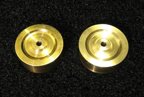
I made them thicker than the plan (like everything else). I'm trying to get these engines to run as slowly as I can, and figured the extra mass couldn't hurt. Besides, the thicker flywheel offsets the look (and balance) of the cylinder hanging off the other side.
Once again, I'm really happy with my little Sherline mill.
This is fun, I should have started sooner.
-
06-16-2009, 04:09 PM #7
Registered
- Join Date
- Mar 2006
- Posts
- 474
Oh yeah, here's the prototype.
Originally there was a commercial model based on this locomotive, called the Cricket, and now the Cracker is a free plan based on the Cricket, and this prototype.
-
06-16-2009, 08:12 PM #8
Registered
- Join Date
- Jul 2006
- Posts
- 1062
Now that's my old mans Christmas present sorted! What about the track? :cheers:
Nice work...keep going Keith
Keith
-
06-16-2009, 09:09 PM #9
Registered
- Join Date
- Mar 2006
- Posts
- 474
 Originally Posted by Kipper

Track's easy; it fits on O-gauge track, so even Lionel and old Marx track will work, even if it's too corroded to run the electric stuff.
Thanks for the compliment!
This thing is designed to be an easy build, or as complicated as you like. I've found many examples online, in many different styles.
-
06-21-2009, 07:42 PM #10
Registered
- Join Date
- Mar 2006
- Posts
- 474
Cut the chimney holes in the rounded smokeboxes yesterday... although, I might not use both of these after all. I think I'll be making one of these as a freelance O-scale locomotive, with an appropriately-sized cab and other details... and the rounded-edge smokebox might not be the best choice for that. I have two slip-fit couplers that I'll also try... it's easier to go ahead and run both of each part while I'm set up... not that this is really a "set up"...just a part stuck in a vise.
-
06-22-2009, 10:40 PM #11
Registered
- Join Date
- Mar 2006
- Posts
- 474
YouTube video link. Not terribly exciting, but I thought I'd post it anyway.
[ame="http://www.youtube.com/watch?v=rTfshaaOQsE"]YouTube - Cracker Live Steam Locomotive Construction: cutting a chimney hole in the smokebox.[/ame]
-
06-29-2009, 10:47 PM #12
Registered
- Join Date
- Mar 2006
- Posts
- 474
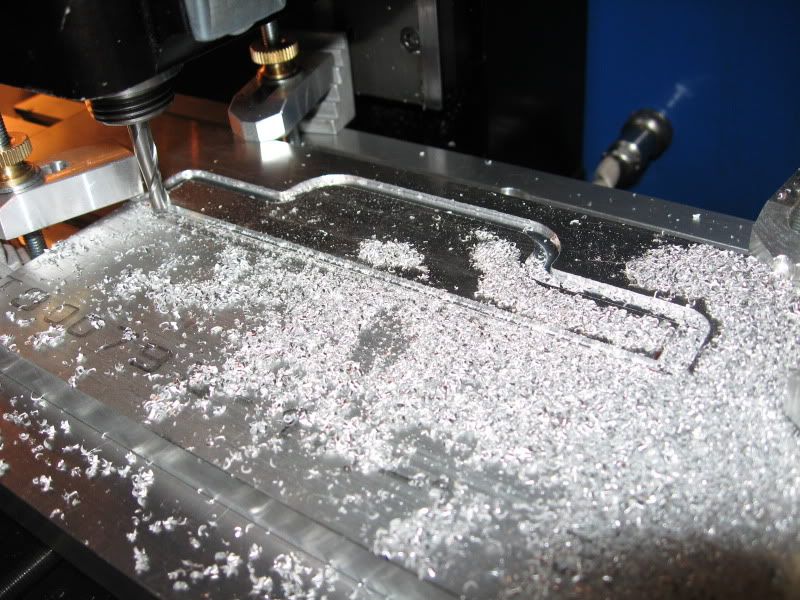
Yet another video...just a pass around the footplate for one of the locomotives, as I cut it out of .125" aluminum. Nothing special.
[ame="http://www.youtube.com/watch?v=CpCG-75cMLw"]YouTube - Cracker Live Steam Locomotive Construction: cutting out the footplates.[/ame]
-
06-30-2009, 10:59 PM #13
Registered
- Join Date
- May 2004
- Posts
- 600
I love following these sort of projects. Thanks for sharing.
-
06-30-2009, 11:57 PM #14
Gold Member

- Join Date
- Jun 2003
- Posts
- 3312
I do too! Nice job.
Phil, Still too many interests, too many projects, and not enough time!!!!!!!!
Vist my websites - http://pminmo.com & http://millpcbs.com
-
07-02-2009, 02:04 AM #15
Registered
- Join Date
- Mar 2006
- Posts
- 474
Thank you both!
I cut the bushing holes in the boilers yesterday. Straightforward, quick and easy.
-
07-02-2009, 09:34 AM #16
Registered
- Join Date
- Mar 2006
- Posts
- 474
Well, my first-ever silver soldering attempt didn't go too badly.
I managed to finish both boilers.
I see a few pinholes around the top bushings, but I went over that arrea twice. I wonder if they'll leak.
-
07-14-2009, 02:04 AM #17
Registered
- Join Date
- Mar 2006
- Posts
- 474
I made boiler mounting saddles from some mica block I had... very heat-resistant stuff.
Filler and safety valves are next.
Here's a few more pictures.
-
07-14-2009, 09:11 AM #18
Registered
- Join Date
- Jul 2006
- Posts
- 1062
Looking good matey :toot: :toot:
Keith
-
07-16-2009, 04:10 AM #19
Registered
- Join Date
- Mar 2006
- Posts
- 474
Thank you! Originally Posted by Kipper
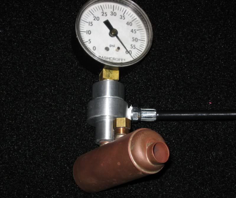
Yesterday I pressure-tested the boilers, ad ran one of the locos on steam.
[ame="http://www.youtube.com/watch?v=Seg6EcyFyiw"]YouTube - Cracker Live Steam Locomotive Construction: First Steam Tests[/ame][ame="http://www.youtube.com/watch?v=uakRJp4p7-M"]YouTube - Cracker Live Steam Locomotive Construction: The second Loco runs.[/ame]
-
07-26-2009, 01:18 PM #20
Registered
- Join Date
- Mar 2006
- Posts
- 474
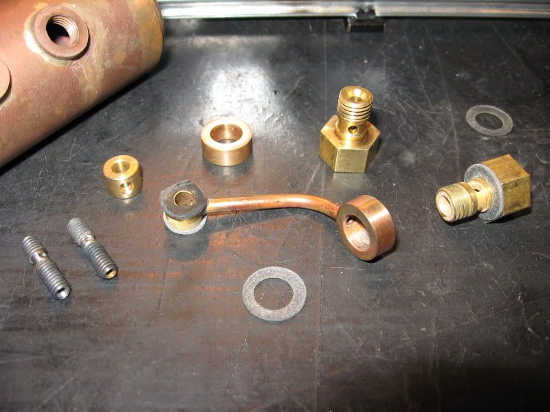
Another Cracker builder, on another forum, asked about the Steam fittings I had made so far. I made them mainly for testing, as a temporary line, but the Cracker's plan doesn't call for anything more complex than what I have here.
Sure thing!Hey,
How about some pics of the banjo fittings and screws. How did you make those ?
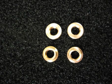
The steam dome fittings, ( the larger in the pic.) are 5/16-24 thread, turned from brass stock, with a lot of extra material left at the head, because I may drill and tap them for either a relief valve, or a filler. (Or, I'll toss these, and make something more suitable.)
The ring portion of the banjo is Phosphur Bronze, turned and drilled. I used one of them for the temporary test line, and since I've read that you can't silver-solder over ANY soft solder, I won't even try cleaning that one, I'll just make another. I'll probably add a groove around the inside at the same time.
The inlet and exhaust port fittings are a bit too simple, just a drilled and turned piece of 8-32 bolt, some turned brass rings, and a couple of nuts that absolutely refuse to seal, always leaking around the threads. The next attempt will use either a cap nut, a bolt, or a straight compression fitting, if only I could find a supplier for something that small.
I don't want any of the lines to be permanently attached at either end; like I said in an earlier post, I'm planning for future maintenance.
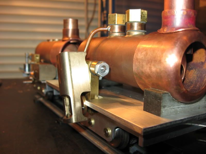
Here's a shot of the fittings. Left to right, two leaky bolts, next time, stainless. Two brass fittings, one soldered to a test line, a phosphur bronze steam dome fitting, and two steam dome banjo bolts.
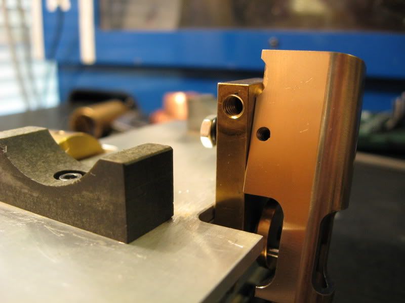
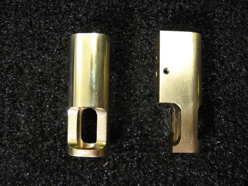
Here's a shot of the inlet port. Nothing special here, other than the clearance notches I had to cut in the cylinder to clear the banjo fittings.
Also visible are the setscrew holding my pivot bolt in place, and the mica-block boiler saddles. The rear saddle bolts to the footplate, the front is captured between the smokebox and the footplate by a through-bolt.