


shopmaninc.com sells liquid colored pigments that work for polyester, gelcoats, epoxy, and some urethanes. Who knows what the liquid medium is? My guess is that it is oil.
Another company sells pigment that is dispersed in epoxy resin:
http://www.raka.com/Accessories.html
If I add a small amount of the pigmented epoxy resin from raka.com to the US Composites epoxy resin from shopmaninc.com, will there be any compatability problem? I am inclined to buy the raka.com stuff, since I know it is epoxy resin that will harden in the final cure and not an oil-based paste. Maybe this is an important detail, maybe not. Any thoughts?
Results 2,041 to 2,060 of 5053
-
09-08-2007, 05:50 AM #2041
 Registered
- Join Date
- Dec 2004
- Posts
- 229
-
09-08-2007, 12:05 PM #2042
Registered
- Join Date
- Aug 2007
- Posts
- 20
McGyver
Increasing the flexural stiffness by putting a high modulus material like steel on the outside of the Filled epoxy core is maximising the performance of your design, nothing wrong with that. I know cast Iron machine bases are not the most efficient structures, though box ways are quite good. Other advantages of using a steel shell over an epoxy core like you mentioned may be, protecting the epoxy, providing a good bearing surface, providing an easier means of attaching machine components and a symmetrical structure is less affected by differential expansion.
Dfro your design seems complex but it might work, about supporting your linear rails, the mounting bases need good bearing on the epoxy base, I would suggest using some form of fine epoxy grout to fill any gap under the linear rail mounting blocks. I use epoxy to level machine parts but I use a machinists level to set up the part level with shims then remove the part smear on epoxy then replace it tap, it down, and check the level again, this is how many large machines are aligned, often cement based grout is used but this is useless for small parts and small gaps.
-
09-08-2007, 10:29 PM #2043
Registered
- Join Date
- Jun 2005
- Posts
- 1435
Surely the contact angle between liquid epoxy and solid epoxy will be virtualy zero, and thus the liquid will flow out with the smallest possible distortion from a truly level surface ?
In my earlier post, I was contemplating pouring the final surface over an existing casting, not greatly dissimillar for the conditions of the people making a floor level surface, where the final pour is over several layers of the same epoxy.
I wonder if a small scale experiment would produce the same surface effects as a larger one ?
If a small mix was produced, with a sample placed in a fridge while the bulk was poured into a small mold, and warmed, there would be the possibility of testing the effect with identical epoxy mixes.
JohnIt's like doing jigsaw puzzles in the dark.
Enjoy today's problems, for tomorrow's may be worse.
-
09-09-2007, 12:20 AM #2044
Registered
- Join Date
- Dec 2004
- Posts
- 229
E/G mill base
Here are some initial cad drawings of the mill table I want to make:
I propose to reenforce the table with 1" x 1" square steel tubing bolted to 1" x 3/4" solid steel bars. I will be drilling into the solid steel bars to attach the linear guide rails to the table, once I have poured the leveling epoxy. I will also drill an even grid of tapped holes in the other solid bars. There are four sets of four steel nuts that will secure the stepper motor plates on the sides of the casting. One set of four nuts wedges the other set which is across the table using threaded rod. Maybe overkill. I could just extend some bolts into the casting. Another set of four steel nuts will hold the leveling bolts and feet. These will be bolted and 'jb welded' to a steel tube before casting the table. All of these nuts will most likely be the long hex nuts you can get at any harware store - not round like I have in the drawing.
I also will fill the hollow steel tubing with some two part urethane foam that I have.
All of the reenforcement is probably overkill, but it is fairly cheap compared to the high quality, massive, stable, accurate table that I hope I will be getting. To me it seems so easy to cut some hollow and solid steel bars, drill some bolt holes, bolt and 'jb weld' everything in place, and cast the part. Then the real beauty of this method comes when you pour the leveling epoxy and let gravity create for you a super level surface, regardless of how big it is. It's just elegant. No worries about weldments warping. No hours, days, and weeks trying to get things lined up (at least on the table). I will gladly pay a few extra dollars in steel tubing to save all of that leveling, grinding, scraping, truing, and treating/aging of welded parts.

Top view of the table. Notice the raised rounded edge that circumscribes the top of the table. This is how I propose to contain the leveling epoxy. It is 1/8" deep. I will route this shape in the mold with a round endmill. The nuts that I attach the stepper motor plates to will extend 1/4" out of the sides of the e/g casting.

Here is a closeup of the rounded edge. I think the rounding will minimize the maniscus. The rectangles are where the 1 x 3/4 steel bars show at the surface of the rough casting. These will be buried under the 1/8" of leveling epoxy.

Here is a bottom view. The nuts that secure the leveling feet will extend 3/8" from the bottom of the casting. The table is 3" thick.

Please, let me know what you all think.
-
09-09-2007, 01:42 AM #2045
Registered
- Join Date
- Apr 2007
- Posts
- 777
Dave,
Your design looks quite good.
The only thing I wold worry about and this is gut feel, not analysis would be putting the threaded rod and nut for the axis mounting plate within less than an inch of the edge of the table. I don't know how much is enough but I am a touch anal and would worry. I'm pretty sure that you're using the steel tube in the middle of the sandwich mainly for alignment as steel on the neutral axis does relatively little good strength wise.
The threaded rods are excellent as they will ensure that any kind of tensile load placed by tightening the bolts will be borne by the steel instead of the E/G which doesn't like tension.
The only other thing I might suggest and this is also intuition rather than analysis would be to use trapezoidal shaped steel bars: mill the sides at an angle so that they end up fitting in like keystones. I don't have any data on the adhesion of E/G to embedments but if you cranked a bolt really tight onto the embedment with a part that put the force on the E/G, there is a small potential for it turn out poorly which would be lessened by the trapezoid shape placing the E/G above it in compression.
I'd have to agree with greybeard that epoxy on epoxy ought do make the meniscus as small as possible. When trying to attain .0001 to .001 accuracy however, I don't know what the effect of the meniscus will be and how far towards the middle of the table it goes. I think Dave's answer is as close as we can come for constrained epoxy at minimizing the meniscus.
Also, on the matter of carbon black, it definitely can be hard to disperse. An apps engineer at Cabot suggested the use of Monarch 120 as it is easier to disperse than some of the finer grades. Everybody looks at me funny but I think well dispersed fine carbon black will provide some interesting surprises in the material properties and when I get my disperser ordered, it will be among the first things I try.
Regards all,
Cameron
-
09-09-2007, 04:34 AM #2046
Registered
- Join Date
- Jul 2006
- Posts
- 1256
plates etc.
Never had any mix problems with carbon black AKA Monarch 800.Walter may have used it.Any comments Walter?
To use Raka pigment dispersed in their resin,added to 635 is an unpredictable result.
Miniscule meniscus is miniscule.It only occurs at the miniscule edge.Just mount your rails one inch or so from the edge which is a good idea anyways.
Gravity will work for us,leveling the epoxy to the curvature of the earth,or 8"/mile.Some plate pics:
For Walter&Martin"The beer is flat":cheers:L GALILEO THE EPOXY SURFACE PLATE IS FLAT
-
09-09-2007, 05:51 AM #2047
Registered
- Join Date
- Dec 2004
- Posts
- 229
I am having a 'duh' moment. I could blend the carbon black power in the US Composites 635 resin ahead of time, just like raka.com does. Whip it in for as long and as hard as I want. I could also put the resing in a glass pan and scrape and mull the powder into the resin with a putty knife. I could then pull a vaccuum on the resin and let any other bubbles settle out over night. Then I can mix the carbon black/resin mixture with the hardener when I need it. However, it might be really cool to put a logo on the table and cast the leveling epoxy clear, so that the logo and the steel bars are visible. Might look very pro, like the precisionepoxy.com surface plates.
Premixing all of the various powders (except the quartz) into the resin ahead of time, might be a good idea for the e/g mixture, also. Then the air can be fully vaccuumed out without the worry of the epoxy curing. And it can be given time to settle out over several hours or days. Maybe the resin is too thick for this to be practical. Or do this to the hardener, whichever one is thinnest in viscosity. What do you guys think?
Cameron and Larry, where can I get the carbon black powder that you are talking about. Cameron, I like your thoughts that the carbon powder will make the leveling epoxy harder. Some experiments on this would be good. What is a disperser? Are they expensive?
I agree with you about placing the motor plate nuts deeper in the casting. I will change that.
When you talk about making the trapezoidal shape, do you mean the smaller surface of the steel bar is facing up, touching the leveling epoxy, and the larger surface is facing down, touching the crosswise hollow steel tubes?
Cameron, I am not sure what you mean by neutral axis.I'm pretty sure that you're using the steel tube in the middle of the sandwich mainly for alignment as steel on the neutral axis does relatively little good strength wise.
Another thought. I have read many times about how costly it is to recondition mills and lathes - several hundreds to several thousands of dollars. Just shipping a lathe or mill to a reconditioning company can be several hundred dollars. Part of why I want to build these machines myself is to engineer easy reconditioning into the machine from the start. If you ever wanted to 'recondition' the surface of the e/g mill table, just attach a hand router to a board, set the router bit to an 1/8" depth, and route out the leveling epoxy. Then, relevel the table and pour another leveling epoxy coat. Relocating and redrilling and tapping the holes might be a little challenging, though. I would probably plug them with steel plugs that are epoxied in place and redrill and tap them after the new leveling epoxy is cured. Still not a very difficult operation.
Thanks for the comments,
Dave
-
09-09-2007, 06:46 AM #2048
Registered
- Join Date
- Jun 2005
- Posts
- 334
Dfro,
In an E/G mixture with a low resin/aggregate ratio, entrained air is not something that should be solved with vacuum.
As Walter pointed out from his castings; vibratory compaction is crucial.
You must vibrate the aggregate/epoxy mixture into its optimal packing density. The entrained air will take care of itself (or should I say, physics will take care of the air) and can be helped using de-airing agents like BYK A525.
Having said all this, what are your plans for vibrating this mass? How much will it weigh?
Have you thought of molding this upside-down? You can get rid of 2/3 of your steel this way.
Jack
-
09-09-2007, 06:57 AM #2049
Registered
- Join Date
- Jun 2005
- Posts
- 334
Cameron,
On the subject of carbon black; I think you're right but I suspect the only way to optimally mix this with a low resin/aggregate ratio would be to use ultrasonic mixing.
Excluding the carbon black discussion, I wonder what packing density could be achieved using ultrasonic’s. Some of the aggregate would abrade down to smaller sizes and liquefaction would allow the epoxy to mix in very nicely!
On the down side, my gut tells me you’d need lots of energy (Kilowatts) to vibrate something like 100 lbs of E/G. Emitters of that power aren’t cheap if I remember, but I’ve not checked eBay yet.
Jack
-
09-09-2007, 08:35 AM #2050
Registered
- Join Date
- Dec 2004
- Posts
- 229
Jack,
In respose to your comments:
I plan to buy a $40 cement vibrator from Harbor Freight. It looks like what Walter is using. I will probably glue a sheet of rubber to the bottom of it to make it stick a little to whatever it is vibrating. I suspect the table will weight a couple hundred pounds.Having said all this, what are your plans for vibrating this mass? How much will it weigh?
Molding it upside down is exactly what I plan to do. I also plan to put a melamine/mdf caul plate on the top of the mold (the bottom of the mill table casting) and vaccuum bag the casting, while it cures. I am hoping this will help to get a dense casting with few air pockets. I have a 18 x 24 surface plate that I will place the mold and vaccuum bag table on to ensure the top of the mill table is as flat as possible after it is cast and turned right side up. Before I cast the mill table I will test the vaccuum bagging on a sample, most likely.Have you thought of molding this upside-down? You can get rid of 2/3 of your steel this way.
The six solid steel bars on the top of the table are to provide steel that I can drill and tap holes into for affixing the linear guide rails. Not knowing exactly where the holes are going to be, and not wanting to worry about perfectly aligning all of the holes, I have chosen to imbed solid bars in the casting. Once I get the guide rails, I can center punch, drill, and tap the holes. I also plan to attach another table surface that I can mill flat once the whole machine is working. It will probably sacraficial pieces of mdf to start with. I do not plan on using the level epoxy surface plate as a table to hold down workpieces and vices. Drop an end mill on the table and there goes your perfect plane (8"/mile curve is pretty perfect to me).
Casting some kind of drain into the table for coolant would also probably be a good idea.
-
09-09-2007, 11:56 PM #2051
Gold Member
- Join Date
- May 2003
- Posts
- 792
That's a good looking table Dfro, you are going to enjoy it.
As Jack mentioned, vibratory compaction is the key. Although these $40 vibrators are quite helpful, they are limited in their usefulness. I've had two under my 150lb mold and always felt a bit limited in terms of frequency. 3400 vpm seems way too low for this kind of work; Still, they're powerful and a real bargain.
I never had problems dispersing carbon black- it gummed up the composite so I quit using it. Here's carbon black:

And here's one of the botched samples, it's been 5 months and the surface "plate" is still soft:
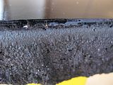
I did overdose, no doubt about it.
I started thinking about surface plates when Bob Warfield posted his table design. Since then, I became a big fan of reverse casting and forgot about making plates. I'll revisit the topic next month when making my rail supports; the idea will be to cast the part, then layer the unfilled epoxy. Once the perfect level is achieved I'll mount a layer of mic6 ground plate on top and entomb the whole thing in (another) casting. I want the level but I also want tough mounting surface. Another reason is that I saw tough E/G surface and it's hard to go back to plasticky unfilled epoxy.
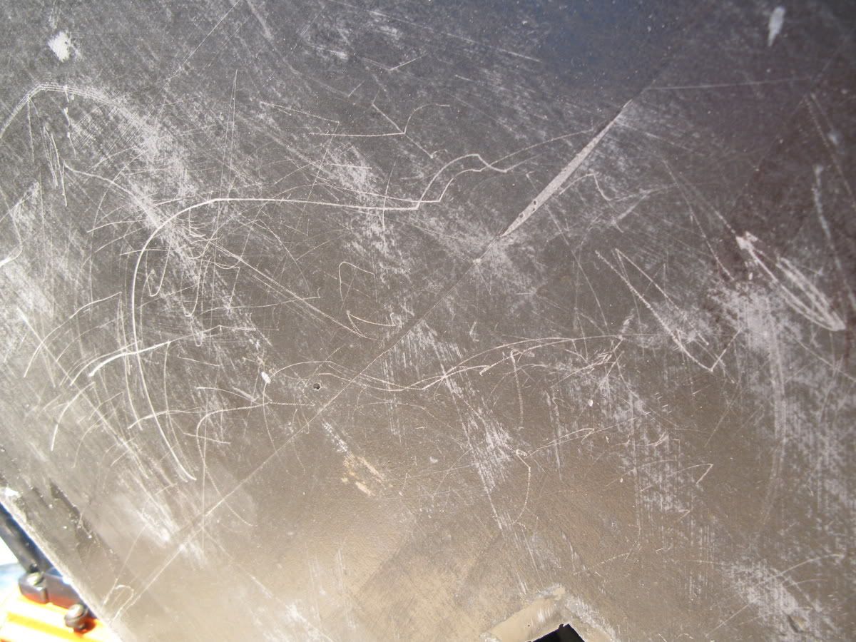
Here it is: tough as nails, from the bottom of the mold and dense beyond belief:

It sounds like rock when tapped; large blacks spots are aluminum oxide, quartz is white/yellow

There is a way to get this tough surface on tables, probably too complicated though. You'd have to cast a standalone surface plate- using TT epoxy- and then reverse cast on that perfect surface. This way, you get the level and the tough surface. But then it still wouldn't be accurate to 0.001" (because of wax release agent).
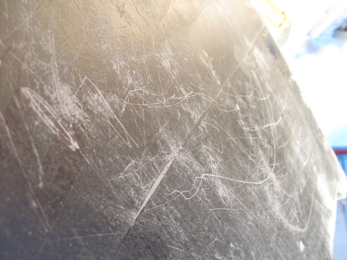
Here's another test. I sanded down the shiny surface of my casting and started using it as a table, throwing things on it, etc.

With solid results.

Overall, I have to say I'm extremely satisfied with this material. It's still in it's infancy, with no additives, way too much epoxy, amateur techniques. And it's already happening- pretty amazing really..
Some commercial E/G companies should definitely start to worry.
_
-
09-10-2007, 12:43 AM #2052
Member
- Join Date
- Dec 2005
- Posts
- 1408
Dear Larry, Originally Posted by lgalla

The last time I looked, there were quite big bubbles on the surface. Somewhere on this thread there are suggestions of how to remove them with blowtorches , exotic chemicals, etc etc.
OK, OK, your particular beer will never be "sporty", but Ireland has a product that might prove more visually acceptable to Walter. I am not sure if the formula is widely available....maybe it's time to start looking...
Best wishes
Martin
-
09-10-2007, 01:01 AM #2053
Gold Member
- Join Date
- May 2003
- Posts
- 792
lol!
Good to see you Martin, always enjoy your posts.
-
09-10-2007, 02:25 AM #2054
Registered
- Join Date
- Jul 2006
- Posts
- 1256
Dave,the carbon black is made by The Cabot Corp.I believe Cameron got free samples.Requesting samples is easy if done through a company name.Good idea to premix the CB and vacuum.I have used Monarch 800 in huge loadings and never had a problem.There are hundreds of different C/B's.Monarch 800 worked for me.
Like the Urethane foam/steel tube.UF has 20psi if contained and the bubbling or foaming action scrubs the inside of the tube,resulting in a good bond.What density foam do you have?US Composites has up to 16/lbs/cuft.
Premixing the aggregates is a no,no.To start a mix the A&B are first.Hard to disperce are second,such as carbon black and micro fillers.
Just hit me,(chair) Walter had surface plate/C/B problems as he probably used 635 slow which will take light years to harden in a thin section.TT/E is for leveling and cure in thin cross sections.Probably TT epoxy has de-arin additives.
Stupid question.If one is making a mill,do you still need a cast iron table with T-slots for clamping fixtures?
Dave you are not aposta drop endmills on your surface plate.Since the purpose of the plate is to have a level surface for rail mounting and alignment of the gantry any endmill drops will not affect the accuracy of the plate other than you will have a hard time combing your hair from the mirror of the plate.
LarryL GALILEO THE EPOXY SURFACE PLATE IS FLAT
-
09-10-2007, 03:23 AM #2055
Registered
- Join Date
- Apr 2007
- Posts
- 777
The resin and hardener both are the viscosity of light corn syrup (600 cps). Once the mixture gets very deep, with lots of aggregate in it, it will be somewhat difficult to vacuum deair. Carbon black can be used to make epoxy harder according to the theory but it has to be dispersed to nanometer sized particles. Unfortunately, this is very difficult to do by simple means so one needs a disperser. The best disperser is an ultrasonic cavitator at $6000-$9000 such as a Sonics and Materials VCX750 or VCX1500. The next best means is something like an ultra-turax T25 ultra-high shear mixer (from IKA USA) with the finest turbine head they make which unfortunately disperses down to about 1 micron where as .05 micron is what's desirable. Originally Posted by dfro
Interestingly enough, Treating the resin component with 20kHz ultrasound from the cavitator causes a 25% increase in strength because the sound intensity is so great that it damages the chemical bonds of the epoxy such that it causes it to crosslink more extensively! I'm going to acquire an ultrasonic cavitator and a materials test machine in the coming weeks.
Carbon black as a nanomaterial is not likely to work unless you have a cavitator or can get the materials dispersed in a compatible liquid. BYK's line of Nanobyk nano-aluminum-oxide might be an option as well. I initially thought it would be fine just to dump some carbon black in and give it a stir but I haven't tried it yet. It may sort of work but from what everyone says, a job of mixing that is beyond the average home shop may be necessary to see decent results.
<pre>I agree with you about placing the motor plate nuts deeper in the casting. I will change that.
When you talk about making the trapezoidal shape, do you mean the smaller surface of the steel bar is facing up, touching the leveling epoxy, and the larger surface is facing down, touching the crosswise hollow steel tubes?
TOP
--------
/...........\
</pre>
Put the big side of the trapezoid towards the bottom so that when a bolt pulls up on the embedment, it will be pulling against epoxy rather than just trying to unbond it from the bottom and sides. As an aside, I was reading along in Slocum's book yesterday and he pointed out that the differing thermal expansion between the E/G and the embedments can cause varying flatness errors on the order of .0001 inch depending on the thermal gradient.
The neutral axis is defined by mechanical engineers as the area in the part where there is no load carried. It is a plane that runs down the geometric center of a beam. You can drill holes in the center of the flange of an I-beam without effecting the strength because the center is the neutral axis. Materials that are farther from the neutral axis are under more stress. In fact, my very first post on this thread was on the topic and had an ascii art diagram:Cameron, I am not sure what you mean by neutral axis.
http://www.cnczone.com/forums/showpo...&postcount=944
Reconditioning is harder than just the table. If the ways wear, then they have to be re-trued and scraped etc. but what you said about the table is true. I'd just make some teflon shoulder bolts and screw them into the holes rather than worry about retapping etc.Another thought. I have read many times about how costly it is to recondition mills and lathes - several hundreds to several thousands of dollars. Just shipping a lathe or mill to a reconditioning company can be several hundred dollars. Part of why I want to build these machines myself is to engineer easy reconditioning into the machine from the start. If you ever wanted to 'recondition' the surface of the e/g mill table, just attach a hand router to a board, set the router bit to an 1/8" depth, and route out the leveling epoxy. Then, relevel the table and pour another leveling epoxy coat. Relocating and redrilling and tapping the holes might be a little challenging, though. I would probably plug them with steel plugs that are epoxied in place and redrill and tap them after the new leveling epoxy is cured. Still not a very difficult operation.
Thanks for the comments,
Dave
I'm going to be on travel this week so I may not manage to post quite as much.
Regards all,
Cameron
-
09-10-2007, 03:32 AM #2056
Registered
- Join Date
- Apr 2007
- Posts
- 777
John,
I've got the data from de Larrard I promised you and a paper by Staynes in an envelope and it should get out in a day or two.
Martin,
In regards to our discussions on meniscuses, if you PM me with your mailing address, I can send you a small piece of teflon sheet in a week or so after I get back from travel.
To all,
If anybody has a use for a box of 25ea 2 inch long 3/4 dia 10tpi Grade 5 machine bolts, PM me and we can discuss it. I got a part number wrong the other day and accidentally ordered a box. . .
Regards all,
Cameron
-
09-10-2007, 04:55 AM #2057
Registered
- Join Date
- Dec 2004
- Posts
- 229
But seriously, once I have this glass smooth flat mill table surface, (which I never concieved would be possible until you thankfully brought it to my attention) I want to protect it from wear and tear. I am considering attaching aluminum bars, to make a 'T' slot table configuration, like the x2 mini mill e/g table that is being sold:Stupid question.If one is making a mill,do you still need a cast iron table with T-slots for clamping fixtures?
Dave you are not aposta drop endmills on your surface plate.Since the purpose of the plate is to have a level surface for rail mounting and alignment of the gantry any endmill drops will not affect the accuracy of the plate other than you will have a hard time combing your hair from the mirror of the plate.
http://www.cnczone.com/forums/attach...chmentid=23056
If I don't do that, I will attach sheets of mdf to the epoxy surface plate, most of the time.
Larry, would you recommend the 'Kleer Koat Table Top Epoxy' that shopmaninc.com sells to make the epoxy surface plate?
With all of the comments on how hard it is to fully disperse carbon black powder into the resin, here is what I propose to do. I will mix and mull a small batch of c/b into some TT epoxy resin, vaccuum it and wait a day for it to de-air, mix it with the hardener and pour a very thin coat of the black epoxy on the table - just enough to cover the steel bars and any surface imperfections in the rough casting. I will wait for it to cure a little and then pour a clear coat up to the top of the ridge around the table. Then there are no worries about the powder messing up the surface.
Cameron, thanks for the explanations.
Here is another thing I am going to add to my mill table design. In order to attach the linear guide rails straight in the 'y' direction, I would like to have a flat surface on one of the sides of the e/g mill table. So, I will also cast a ridge into one of the sides of the table. Then after the top of the table has the leveling epoxy cast and cured, I will turn the table on its side, level it with machinist jacks and water (and my precision level), and cast an epoxy surface plate along one side. Now I can use that surface and a dial indicator to indicate the rails' straightness along the 'y' axis. Once that rail is straight, I can use it to get the other rail straight. What do you guys think?
More cad sketches on the way.
-
09-10-2007, 08:12 PM #2058
Registered
- Join Date
- Nov 2006
- Posts
- 1698
Here ya go: Originally Posted by martinw
http://www.barkeeper.ie/3page.asp?me...63&Subpage=108

-
09-11-2007, 12:00 AM #2059
Registered
- Join Date
- Dec 2004
- Posts
- 229
Walter,
Those are really beautiful e/g parts you have made, recently.
Could you share what formulation you used to make the table you describe in post #2052? What you are describing is good enough for me. I want to get casting and building my first cnc machine, pronto! As you guys perfect the formula, and find cheap and easy ways to find most of the materials, hopefully I will be on to an e/g cnc lathe or a larger mill, where I can benefit from the new formulas.
I have found a local foundry supply company that will sell me 100 lb. bags of foundry silica sand in these sizes - F110, F95, F80, F70, F55. I am assuming that F110 means #110 screen sand. I believe F55 will give me grains that are approximately .011" in size, and F110 gives me about .006". Do I need larger silica grains - fish tank kind of stuff? Are you putting small rocks/pebbles in your mix anymore?
Also, where did you find the aluminum oxide, what mesh size, and what percentage of it are you using?
I also plan to use US Composite 635 epoxy for the e/g and Kleer Koat TT epoxy for the surface plate, sold at shopmaninc.com.
As far as the de-airing BYK-A 525, I think I might skip it. Is there a company that sells it in small quantities? I got on BYK's web site and they have a shopping cart function to order samples, but they do not give you a price. You send them your mailing address, and then what? What if you are not a company? How long will it take to arrive, whenever they feel like sending it? What if I need more of it in the future? I don't think I want the success of an e/g formulation to hinge on whether or not a big, high-tech, global corp decides to give out a sample.
Another idea for a cheap and available way to add carbon powder to the mix might be powdered charcoal, available from art supply companies, i.e.:
http://www.dickblick.com/zz289/51/
I just googled 'charcoal' and read that charcoal is 50-95% carbon. Any thoughts?
Thanks,
Dave
-
09-11-2007, 12:41 AM #2060
Member
- Join Date
- Dec 2005
- Posts
- 1408
Dear Cameron, Originally Posted by ckelloug
Thank you so much for the kind offer of a sample, but there is really no need . I have just realised that there is a small strip of PTFE on my skis between the boot bindings. That should be a big enough area on which to observe the phenomenon.
BTW, it's menisci...( prononced ..SKY,not SKI)
Safe travel
Best wishes
Martin

 Reply With Quote
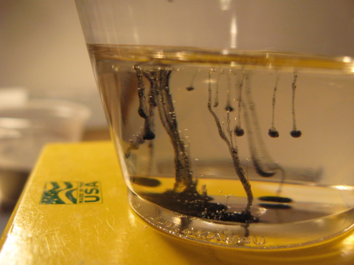


Similar Threads
-
Epoxy Granite In Practice (Mineral Casting, Polymer Concrete)
By johnohara in forum Epoxy GraniteReplies: 71Last Post: 08-25-2020, 01:18 PM -
Voice Your Opinion On "POLYMER CONCRETE FRAME" Thread!
By walter in forum PollsReplies: 14Last Post: 11-13-2015, 02:57 AM -
Epoxy granite (Mineral casting, Polymer concrete)---Particle size distribution
By Steven.ji in forum Epoxy GraniteReplies: 9Last Post: 01-15-2014, 11:39 AM -
Index to "Epoxy-Granite machine bases" thread
By walter in forum Epoxy GraniteReplies: 13Last Post: 12-02-2011, 05:45 AM -
Epoxy-Rice Machine Bases (was Polymer rice frame?)
By mdierolf in forum Mechanical Calculations/Engineering DesignReplies: 18Last Post: 11-02-2008, 04:16 AM
