


during the casting the epoxy heats as it cures. this makes the steel expand, but the granite (quartz) does not expand very much. the epoxy expands too but flows through the quartz. if the mix of quartz is right, it will not shrink much when it cools.
so shrinkage in the steel could cause the deforming.
i imagine the big companies compensate for, or control expansion and contraction when mixing precision metal parts into the casting. there are likely lower temperature epoxies, and there are also steels that might have an expansion rate more in line with the granite. (they use Inconel for precision carbon moulds for this reason).
ive been wanting to try an EG structure but this exact problem has me thinking that i shouldn't try to embed steel parts into it. schneeberger uses a separately cast aluminium oxide mix for linear rail beds which is what i think i will try.
Results 4,741 to 4,760 of 5053
-
01-04-2014, 12:04 AM #4741
 Junior Member
- Join Date
- Jun 2007
- Posts
- 3891
-
01-04-2014, 09:48 AM #4742
Registered
- Join Date
- Jul 2013
- Posts
- 27
Sure. The steel strips are 20x20mm, C45 (1.1730) material, 770mm long. Epoxy concrete thickness above the steel is 45mm and the threaded rods meant as 'anchors' between steel strips and subassembly (and later subassembly to rest of the EC) are M8. Originally Posted by gozos

Some more information: here is a rough drawing of the entire mill. It is rough in the sense that I stopped drawing as soon as I figured out the dimensions of the parts needed. I did not draw all the bolts, for example.

Table base is 800x800mm, working envelope will be somewhere around 650x500x200mm with a part of it intentionally outside the base table.
The mill is intended to replace my current CNC-ed BF20 (G0704) and supposed to do at least what that mill can do. Most of the milling I do is aluminium and some steel. Pure hobby work, no production or otherwise paid jobs.
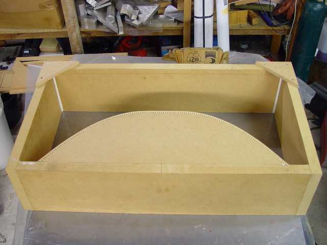
The gantry excluding the 'feet' measures 780x400x200mm and contains an arch in the middle to increase stiffness. I am either milling 'high' parts that are not so large, or flat and low parts (sheet material), so no need to have the same working height everywhere.
Because a massive EC casted gantry would become far too heavy, I intend to make it partially hollow. I intend to put a lot of 50mm polystyrene balls on the inside, keeping the outer wall thickness at >25mm and the webbing between the balls at 10mm at the thinnest location or so. This results in a 'torsion box'-like structure with an estimated weight of 70-100kg.
Here is a drawing with rectangular pockets:

But I will use spheres as the pockets instead of box sections.
An early picture of the mold for the gantry:
Here is a picture of the base of the machine:
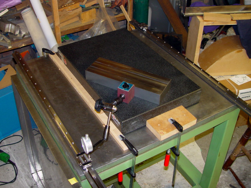
The entire idea behind this machine was to buy a table with a flat surface which I could use as reference for almost every step in the construction process. Mounting surface for the rails, reference surface for the steel strips in the gantry while casting the EC, etcetera. I am doing this in my shed and I do not have access to gridning machines etcetera. This idea did not work out too well since the flat surface was not flat enough. So I borrowed a granite surface plate to use as reference and mounted the rails on secondary cold rolled steel strips that are adjusted flat and parallel. After adjusting I filled the space between table and strips with an epoxy/quartz flour mixture.
Well, that is what keeps me busy lately in a nutshell. It is a little offtopic, but it might provide some insight in what I am trying to accomplish with the EC so I hope the moderators won't be too mad.
I used epoxy with a very long pot life (240 minutes) and hardening time (R&G resin L plus hardener GL2). I can hardly imagine a lot of heat generated in such a thin slab. Although I did circulate 30-35 degrees C air over the EC during the curing; temperatures in the shed are a bit too low for room temperature curing only (ca. 15 degrees C was the best I could do; my shed has a lot of, uhm, 'natural ventilation'). Maybe I should not have done that. Originally Posted by ihavenofish
So do I. The question is: how do they do it?i imagine the big companies compensate for, or control expansion and contraction when mixing precision metal parts into the casting.
-
01-04-2014, 10:24 AM #4743
Registered
- Join Date
- Jun 2013
- Posts
- 31
You have answered you're own question to a degree. The use of aluminium trihydrate has also featured well , not only as a filler and flame retardent ,but also as a shrinkage inhibitor.
-
01-04-2014, 10:42 AM #4744
Registered
- Join Date
- Jun 2013
- Posts
- 31
Another thing we have used in reducing(not stopping) shrinkage in epoxy. PUR, and polyester castings is temperature control of casting materials and the reinforcing. The term "exotherming" is generally applied to this heat creation caused by chemical reaction. This is necessary to attain structural strength and integrity of your finished component. If you need further advice regarding reduction of shrinkage, I could suggest you contact the technical departments of either Sika Group | Sika AG , Dow Chemical Corporate Website - The Dow Chemical Company , or any other top line epoxy manufacturer. The are generally very helpful. I have been involved with mold making in epoxy, polurethane and polyester and other materials for over 25 years and have always referred any queries to the relevant chemists in involed and have saved a lot of money and time by not trying to hack it on my own.
When I have spare cash and time I love experimenting!
-
01-05-2014, 01:31 AM #4745
Junior Member
- Join Date
- May 2007
- Posts
- 68
Hi DaBit
Nice to see you using a surface plate to create a flat plane. The so called "negligible" shrinkage of epoxy appears to be working against you, that might explain the bow
Did you set the screwed rods very tightly in the tapped holes at the back of the steel support rails? I suspect you did?
Did the mould exotherm much and heat up? that might cause contraction on cooling?
Looking at the images the you have achieved a very good finish what percentage of epoxy did you use by volume?
I have cast on a surface plate before and it worked well using cast in tapped metal inserts to attach other parts to later. This should eliminate the differential shrinkage that appears to have bowed your rails as shown in the following link.
New technology in Model Engineers Workshop | Model Engineer
I did use steel reinforcement, the casting did not bow, maybe that is because the steel reinforcement was placed in the approximate centre of the mould?
I am surprised that your mould bowed.
Regards
John
-
01-05-2014, 10:10 AM #4746
Registered
- Join Date
- Jul 2013
- Posts
- 27
The shrinkage seems to be the root cause. The 'bow' is also worse on the larger first cast (lighter part on the picture in post #4739), and less on the smaller remainder (darker part; I played a little with dye percentage). Originally Posted by JohnMcNamara
Hand-tight and then a little twist with a pair of pliers. Not extremely tight, but I did use some Loctite 2701 on the threads to make a very solid connection.Did you set the screwed rods very tightly in the tapped holes at the back of the steel support rails? I suspect you did?
No. The epoxy system used is very, very slow. But I did heat the mixture slightly on the top with ~35C air coming out of a modified hair dryer to keep temperatures above 20C. This is done because I was not able to get the room temperature up to above 15C.Did the mould exotherm much and heat up? that might cause contraction on cooling?
I suspect that I should not have done that....
By volume, I don't know. I mix the aggregates and epoxy by weight which I find much easier. I also used weighting while determining the optimum mix.Looking at the images the you have achieved a very good finish what percentage of epoxy did you use by volume?
By weight it is somewhat more than 8%. 8% results in a dry mixture (fully wetted out aggregate, but not pourable), 9% is already too wet.
Since I did not have too much success vibrating the mixture, the method to make the second pour was this:
- Make a dry mixture with ~8% epoxy by weight.
- Fill the mold with a layer of approximately 20mm.
- Using a hammer and a piece of wood, compact the mixture.
- Using a paintbrush, wet out the surface of the layer with neat epoxy. No pooling, just shiny and wet.
- Add another layer of epoxy concrete, and hammer it. While this compacts, the small layer of epoxy added to the first layer is forced through the new layer. compaction is done when the surface of the new layers starts getting wet.
- When needed, use the paintbrush to make the surface 'shiny' again and repeat until the mold is filled.
I will check the flatness of the casting itself, but I think the casting itself is as flat as the wood used for the mold was. It is the steel that bowed (and you need a surface plate or indicator to determine that it is bowed; visually everything is straight).I have cast on a surface plate before and it worked well using cast in tapped metal inserts to attach other parts to later.
I did use steel reinforcement, the casting did not bow, maybe that is because the steel reinforcement was placed in the approximate centre of the mould?
I am surprised that your mould bowed.
Using threaded inserts and atttachting the steel parts later would have been a better idea. Or using smaller pieces of steel strip independently mounted in the mold. Then, if there is a 1mm gap between the separate pieces in the uncured EC it would shrink to, say, 0,98mm gap but the surface would still be flat.
-
01-05-2014, 03:05 PM #4747
Member
- Join Date
- Jan 2005
- Posts
- 15362
DaBit
To eliminate one problem, would be to have the steel stress-relieved, the C45 steel like you are using is also not flat to start with, it should be reground after everything is finished anyway
You could use regular EN36 MS stress-relieved, rough machined & finished machined/ground/scraped after casting, would be the correct way to do it, even cast iron inserts/bar would be better to use then C45/1030 materialMactec54
-
01-05-2014, 07:55 PM #4748
Registered
- Join Date
- Jul 2013
- Posts
- 27
I used regular cold rolled ST37 strip to mount the rails on the table, and these strips are beautifully flat. Measured from the (class 0) surface plate onto the carriage reference surface there is +/- 0,01mm deviation. I do have 2 set screws next to each rail mounting screw, but once the first few were adjusted the rest was a piece of cake.
Therefore I thought that using pre-ground C45 strip in the gantry mold would be a good idea. These were available in 1000mm lengths, many other steels only in 500mm length, and they are quite affordable.
I am fairly new in the mechanical/construction world, so I really cannot tell all those different flavors of steel apart. I also didn't need special properties besides being flat. Before molding them in they were flat to within 0,025mm, and that 0,025mm was mainly caused by a light bend in one of the strips.
BTW: the end goal is not a machine that is accurate up to several microns over the entire working envelope. If I can mill smaller parts with a precision better than 0,05mm I am happy. I can do that now on my BF20 also. Larger parts are often wood or plastic, and +/- 0,1mm tolerance is OK then.
That said: more accuracy is always better and often it is just as hard to do things accurate than inaccurate.
I will see what milling/grinding the surfaces flat again will cost me. It is necessary anyway.
-
01-06-2014, 08:54 AM #4749
Junior Member
- Join Date
- May 2007
- Posts
- 68
Hi DaBit
Some machine builders I have seen on the net using epoxy mineral cast frames bed the rails, rail supports and other parts in an epoxy grout as a secondary operation after the main casting has been made with threaded steel inserts placed ready for attachment of other parts later, than allowed to cure for a few days.
This is a good method, particularly if you design in small jack screws to bear against the main casting and oppose the actual attachment cap screws to correct any small errors. They can be in the smaller parts or on the main frame itself
Actually an old idea, My lathe a 30 years young VDF 21RO originally had a copy attachment. When I removed the attachment assembly all the parts had small grub screws to precisely jack everything into alignment against the main bed casting. I have seen it on other machines too.
I like the way you placed the small surface plate on the machine base to slide you indicator around (your photo above in this post)
So extending the jack screw idea the process is simple.
1. Set the part up with jack screws and your measuring method. Then carefully remove (or use a pourable grout)
2. you may need to make a dam around part to contain the epoxy grout. (Or better still shallow pockets in the casting to create a dam), the pockets do not have to be high accuracy.
3. Pour or place the epoxy grout. and install the part
4. Recheck the alignment before the epoxy grout sets!
The above covers levelling but not straightening parts.
For that one method is to make small disks with an eccentric hole off centre for adjusters. if you place threaded inserts around the edge of the part you can use the disks on a set screw to lever the part sideways into precise alignment. They can be removed later and painted over if you don't like the look for aesthetic reasons.
The accuracy using this method can be very high, Constrained only by the instrumentation you have to hand and the time it takes to tweak out that last tenth.....
Regards
John
-
01-06-2014, 10:18 AM #4750
Registered
- Join Date
- Jul 2013
- Posts
- 27
Hi John,
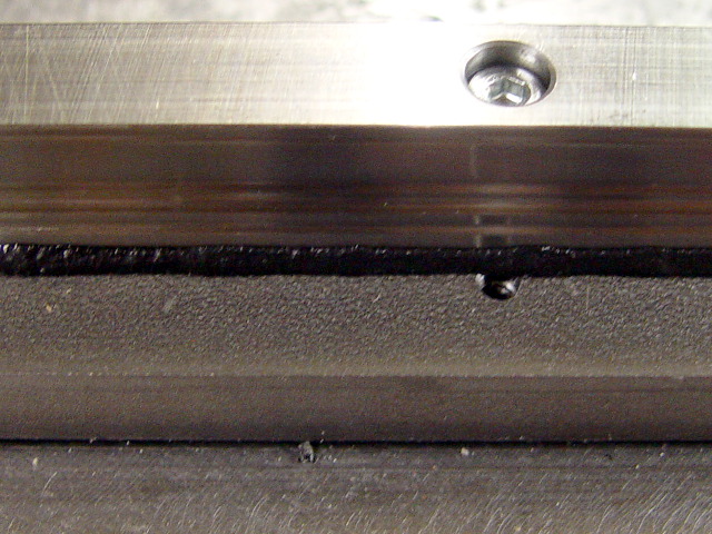
I used that setscrew/jackscrew thing for the rails on the table:
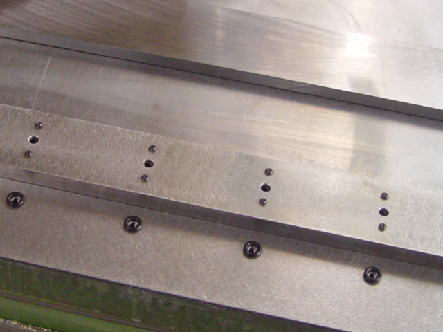
There are small rubber rings between the strips and the table surface to keep the filler injected between the parts away from the cap screws used for mounting the rails.
Straightening the rails was done using a reliable flat ruler and a feeler gauge. I straightened measuring on the reference surface of the (preloaded) carriages. After all that is what must be straight:
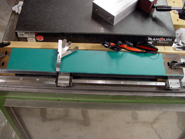
No need for eccentric discs; the mounting holes in the rails are slightly oversized so some adjustment is possible. +/- 0,15mm or so, which should be plenty.
After levelling and straightening the rails a few times (things tend to pull slightly out of 'flat' after the first adjustment; a second session is needed to correct that), I filled the space between table and strips with an epoxy + quartz flour + 0,25-0,4mm aggregate. Also epoxy concrete, but without the larger aggregate.
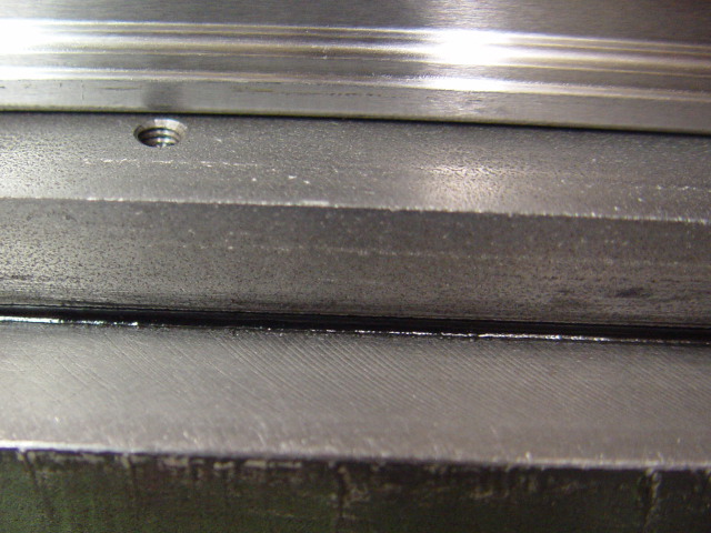
The 'master' rail was secured horizontally using a simple bead of EC:
The mix used for this is very stiff and contains the absolute minimum of epoxy and maximum of sand (0,25-0,4mm). This makes a very stone-like mass which is fairly easy to break if I need to replace the rails for whatever reason.
Note: the slave rail was not secured horizontally. That's not necessary if the gantry is stiff enough.
I will use the same method for mounting the gantry on the carriages. Steel plate molded in the gantry, steel plate on the carriages, a few set screws, and once everything is level and square I will fill the space between the two steel plates with EC.
I really wonder why on earth I didn't use the same method for the rail mounting surfaces on the gantry...
Probably too confident that casting on a surface plate would work out fine. Oh well, another lesson learned.
I will request prices for milling/grinding the gantry strips flat, but if that is too excessive, I might still go that route. Although the lack of MDF and aluminium might fool one into thinking otherwise, this is a fairly low budget build (~$2500 excluding electronics; I already have that on the BF20).
-
01-06-2014, 11:59 AM #4751
Registered
- Join Date
- Jun 2013
- Posts
- 31
Very neat job done!!
Hi DaBit
When you compact 20mm layers in future, it is not necessary to wet out the top before placing and compacting the next layer. It is better to take something like a dinner fork and scarify (scratch) the already compacted surface to a depth of 3- 5mm, in other words ,just fluff the surface up. Then place your next layer and recompact. We normally use pneumatic sand rammers to compact polymer concrete that have low resin ratios. An electric Kango rammer/hammer with a 6" x 4" x 1/2" steel plate attached to an old moyl.
Maybe useless info, But thought it might help in future.
P.S: We are in the business of casting everyday
-
01-06-2014, 12:47 PM #4752
Registered
- Join Date
- Jul 2013
- Posts
- 27
Stonemason101: thanks for the information!
The theory behind wetting out the top layer is that the liquid epoxy (with a mixed viscosity of 250mPa.s, which is pretty fluid) is forced through the next layer, driving out the air and reducing air bubbles in the mix. This seemed to work to some extent; the second pour on the rail-strip casting contained less air pockets than the first pour while the epoxy content of the final EC is approximately the same.
If I add the little extra epoxy upfront, the risk of a mixture that is too slushy and sticky to compact by hammering is large (and I did not have much success using vibrating the mix; I probably need to build a decent vibration table for that but hammering a slightly dry mixture works fine). The line between too little epoxy and too much is small, less than 1% by weight.
Speaking of automated hammering: this weekend I bought one of those $20 air-hammers for this purpose. Like this one; the same device is sold under at least 100 brand names. I will weld a steel plate to one of the chisels that came with it, and see how that works. If it doesn't, well, piece of wood and the manual hammer worked well so far.
I will try your dinner fork trick too.
-
01-06-2014, 01:33 PM #4753
Registered
- Join Date
- Jun 2013
- Posts
- 31
Hi D,
The use of a vibe table is only suitable for wet and semi-wet mixes. The ramming system is widely used worldwide in mould making epoxy/sand 'dry' mixes for everything from auto cylinder head blanks to architectural components. By the way , you will have to machine the chisel down to a spigot, which will fit into a sleeve/collar welded to the plate with grub screws on the side for locking. Tried the same thing a couple of years ago, just kept on snapping as the chisels are hardened. Hope this helps. If I get a chance I will video a casting session and post it for you.
Regards Kevin
-
01-06-2014, 01:38 PM #4754
Junior Member
- Join Date
- May 2007
- Posts
- 68
Hi DaBit
Your work looks great.... And it is good to see quality machinery being built in this thread, Lets hope others follow. It needs to move to the applied engineering side, there is a lot of theory that needs to be put into practice.
Yep a good Idea! I also have one of those hammers... However it is an air hog, it also hits really hard and will happily break a brick into pieces. To reduce the consumption use it with a pressure regulator turned way down, it will save your compressor. and make it a lot more manageable. I have not used it for compacting epoxy, just demolition and removing tiles. To do fine work you can set the pressure to just faintly vibrate, at full pressure the chisel will move about an inch unless it is held up against a hard surface.
You mentioned injecting epoxy How did you do that?, with a disposable syringe? or do you have a better tool. at one time I tried to get empty plastic silicone or builders glue cartridges and nozzles to fill by hand then throw away, and use in a cheap builders dispensing gun. Alas I was unable to find a supplier in Australia... Maybe you will have better luck in your part of the world.
Regards
John
-
01-06-2014, 02:17 PM #4755
Registered
- Join Date
- Jun 2013
- Posts
- 31
Hi again D!
Forgot 2 mention that we normally have a wet out ratio of between 0.75% and 0.85% resin to aggregate, depending on aggregate, resin viscosity, and weather ( believe it or not!). The lowest resin to material ratio you can get away with will be your strongest. Even better if you can de-air in a vacuum chamber at -100kpa before casting. Just make sure your timing is spot on , otherwise you have resin going off whilst casting, which I'm sure you know. Check out this vid at 4:02 Haddonstone - YouTube . This is not a "vibrator", this is a rammer for dry casting. It "RAMS" the product into the mould so dense you can de-mould immediately if you have negative rake angles in your mould.
Cheers Kevin
-
01-06-2014, 02:49 PM #4756
Registered
- Join Date
- Jul 2013
- Posts
- 27
@StoneMason101: I am looking forward seeing one of your videos. If you Google around it seems that you won't have any success using EG unless you use the perfect specialty aggregate mix and a high frequency vibrating table setup. My experience is different; the hammered/rammed mixes are of high density (>2100kg/m3) and extremely tough. But I have yet to fill a large and more complex mould....
With the slow epoxy system at least I have the advantage that I can take all the time I need, and with the ramming/hammering system I can use different mixes in different locations (fill a 5mm gap with a wet mixture containing no large aggregates and use dryer mixtures with large aggregate elsewhere)
[edit]
What is the trick behind the 'vapour curing chamber', around 4:23 into the video? Less than 1% of resin certainly is very, very little. Are there any datasheets on the properties of that stone? E-modulus, compressive strength, etc.?
[/edit]
@JohnMcNamara: my posts are becoming slightly offtopic now and then but that's the side effect of posting a question without a separate topic to refer to; without a little background information it is hard for others to provide help. At least I do use some form of epoxy concrete at almost every construction step. Hi, my name is DaBit, and I am an epoxy addict
I tried injecting the EC between the table and strips using a disposable syringe, but that does not work without designing in special features such as holes for injecting.
You will have to mix up to a peanut butter like consistency to prevent the quartz filled epoxy from running out, and then it is too thick for a syringe and generally hard to force into a small (1,5-2mm) gap. The sand filler also tends to block the exit of the (20ml) syringe.
What I did instead: I placed clear packing tape (an excellent release agent) on all the surfaces I didn't want any epoxy on. Then I put a large bead (10x10mm or so) of EC next to the strip, and used a piece of aluminium strip to force the EC bead into the gap by having the aluminium contact the table/strip and forcing the aluminium towards the gap. This is a messy job. You could also use a putty knife, but I preferred the longer (~500mm) aluminium strip since it prevents EC from oozing out and going everywhere at the sides.
Repeat a few times until a royal amount of filled epoxy has exited the gap on the other side so you are fairly sure that there are little or no air pockets left. This method requires you to mix up much more EC than needed to fill the gap, but the minimum batch of epoxy I can accurately mix up is 65 grams. Combined with quartz flour and sand this results in a full disposable soup mug. Plenty to fill many gaps.
Then it is mess cleaning time. As you probably noticed while working with EC, the stuff is fairly hard to wipe away. Paper towels etc. tend to smear the 'mud' around and leave grains of sand everywhere instead of absorbing it, Some acetone or thinner works, but I don't really want to use towels drenched in solvents near fresh epoxy. Some of it might end up in the fresh epoxy. But luckily 'fight fire with fire' also works with EC: you still do have a little neat epoxy in your first mixing cup since you are supposed to weight component A and B, mix in a cup, put the mixture in another cup, mix again, add pigment/fillers, and then use it. Put some of that clear epoxy from the first mixing cup on a paper towel, and use that to wipe the area around the gap clean. Then remove the packing tape, and voila, there is your shiny bead.
BTW: I can get the empty 310ml cartridges here, but in fairly large minimum quantities and high shipping cost. They would be better than a syringe but you are still left with making an auxiliary construction with dams, injection holes, etc.
-
01-07-2014, 10:46 AM #4757
Registered
- Join Date
- Jun 2013
- Posts
- 31
Hi D,The vapour cure is more for GRC and structural components which require continuous moisture to achieve maximum chemical cohesion in the shortest possible time. With epoxy, polyurethane and polyester systems post curing is normally done at 60 degrees C, for a minimum of 8 hours.
Try a little sample mix with 0.85% resin and hammer into whatever mould you have lying around , stick it in your oven overnight and send it in to your local concrete testing station for a test .I think you'll be quite surprised. The average test block should be no smaller than 100mm x 100mm x 100mm.
Ciao , Kevin
PS: For increase in E-mod try adding some Fibrin into your mix, the stuff is incredible for increasing flexural and tear strength in any chemical cast mixture
-
01-07-2014, 11:51 AM #4758
Registered
- Join Date
- Jul 2013
- Posts
- 27
Hi Kevin,
I wonder how I am going to distribute 0,85% of resin evenly through the aggregate? Just keep on mixing, I presume.
I also suppose that I better leave out the quartz flour in the aggregate mix and use 0,25-0,4mm quartz sand as the smallest aggregate fraction? I would say that the flour absorbs a large percentage of the resin due to the enormous surface area of the micron-sized particles, and 0,85% resin is barely enough to coat the surface of the grains.
I do have a 2-stage vacuum pump capable of pulling a much deeper vacuum than required for this, and with the (according to Haddonstone) porous mixtures it might add some benefits to vacuum the mixture. With 8% resin pulling a vacuum doesn't do much.
Regarding the fibrin: do you mean the Sika Adfil fibrin (synthetic polypropylene fibres), or the blood-type fibrin?
Based on the Sika datasheet and polypropylene properties I don't see how those fibers would increase the E-modulus of the final cast. Strength in tension and cracking resistance, yes, E-modulus no. E-glass (or carbon fiber if you have money to burn) seems a better choice then.
I know some pig blood in a cement-based concrete mixture can do wonderful things, that would be the natural fibrin. But I have no clue about it's properties.
-
01-07-2014, 12:29 PM #4759
Registered
- Join Date
- Jun 2013
- Posts
- 31
Hi D,
We use ribbon blenders for mixing. These are very high output machines,e.g. a mix of 350kgs will blend in between 60 and 90 seconds depending on type of mix. You might consider making a mini unit,i.e. 15-20 kgs, for small mixes. Believe me, it's well worth the effort. Here's a pic of my first build, a 400 kg unit in 304 stainless steel.Attachment 217464 (not me in pic, but my good man, Friday!)
You have to experiment with your different micron sizes until you find something that YOU are happy with. The concept of 'dry' mixes goes back about 4000 years, as far as my research picked up! Same as being a kid on the beach with a bucket making sand castles, no different....promise you! Yes, super fine fillers will tend to absorb more resin. Good for wet mixes , not great for dry......... Also make sure that your fillers are denser and glassier. Have you tried micro-balloons or ceramic/porcelain fillers? I even used our local river sand, dried and sieved, as it is high grade quartz.
Anglo-Danish developed Fibrin in 1995 with resounding success in the construction industry. However ,I do not not know if they ever delved into the dark arts of composites.
When I first got my hands on this stuff in '96, I spent months adding it to everything but my breakfast cereal. Epoxies , urethane, polyester, vinyl, silicone and God knows what else. I would take a normal mix of epoxy/acrylic resin/polymer concrete, cast 2 strips , one with and one without Fibrin. Then I'd spend the next day pulling, stretching , twisting, with gauges attached. This was how I found out about the benefits of using Fibrin, not from a data sheet. Adfil also make various types of fibre, not only one generic.
Have FUN!!!
-
01-07-2014, 03:17 PM #4760
Registered
- Join Date
- Jul 2013
- Posts
- 27
Although the entire synthetic concrete mixture optimization thing surely is interesting I am more interested in creating The Almost Perfect Gantry For My Machine.
Mixing up a couple of 0,85% batches with and without quartz flour and the largest aggregate size to see how they perform is certainly worth the effort. Experimenting until mixture #337 is 0.31% better than #336 is not.
Same for the ribbon blender: I have a similar mixing device attached to a hand drill. If yours is only a larger one I think it will do the job. After all I only need <100kgs of epoxy concrete.
The filler materials used so far are:
- ground quartz flour. Grain size several microns up to a few 10ths of a millimeter.
- Washed, sieved and kiln dried quartz sand with grain sizes 0,25-0,4mm.
- Washed, sieved and kiln dried quartz sand with grain sizes 0,8-1,4mm.
- Washed, sieved and kiln dried quartz gravel with grain sizes 2,0-4,0mm.
All clean, pure quartz meant to be used in filtration systems. Makes a very hard mixture. I tried to sand smooth a few rough spots: forget it. The sandpaper is blunt before you can blink your eye. Attacking the EC with a sharp knife only leaves a scratch and a blunt tip.
I do have a bucket full of 60 micron microballoons, but I liked the quartz flour better. Much easier to mix in, and much easier to determine the amount needed since with equal densities (they are all pure quartz..) for the filler materials they can be weighted. But in a very dry mixture I can see the advantages of using spherical microballoons.
Comparing E-modulus of epoxy concrete with and without fibers is more interesting. I don't think it differs that much. Tensile and flexural strength is a different story; the fiber-filled EC would be much harder to break. If fibers also improve E-modulus, how much gain can one expect? A few percent gain is not worth the cost of aquiring; my gantry is a stiff structure by design and doesn't rely on space age material to keep deformation low. Deflection should be very low even with a less than optimal E-modulus for the EC.

(inaccurate simulation at 10GPa E-modulus which provides order-of-magnitude information at best)
If there is time I'll try a dry mix tonight. Very curious. Such a dry mixture would solve all possible shrinkage problems. If there is almost no resin, there is almost no shrinkage.
One question: the aggregate particle size distribution. Do you shoot for a maximum density mixture, or a mixture with slightly more large grains?

 Reply With Quote
Similar Threads
-
Epoxy Granite In Practice (Mineral Casting, Polymer Concrete)
By johnohara in forum Epoxy GraniteReplies: 71Last Post: 08-25-2020, 01:18 PM -
Voice Your Opinion On "POLYMER CONCRETE FRAME" Thread!
By walter in forum PollsReplies: 14Last Post: 11-13-2015, 02:57 AM -
Epoxy granite (Mineral casting, Polymer concrete)---Particle size distribution
By Steven.ji in forum Epoxy GraniteReplies: 9Last Post: 01-15-2014, 11:39 AM -
Index to "Epoxy-Granite machine bases" thread
By walter in forum Epoxy GraniteReplies: 13Last Post: 12-02-2011, 05:45 AM -
Epoxy-Rice Machine Bases (was Polymer rice frame?)
By mdierolf in forum Mechanical Calculations/Engineering DesignReplies: 18Last Post: 11-02-2008, 04:16 AM
