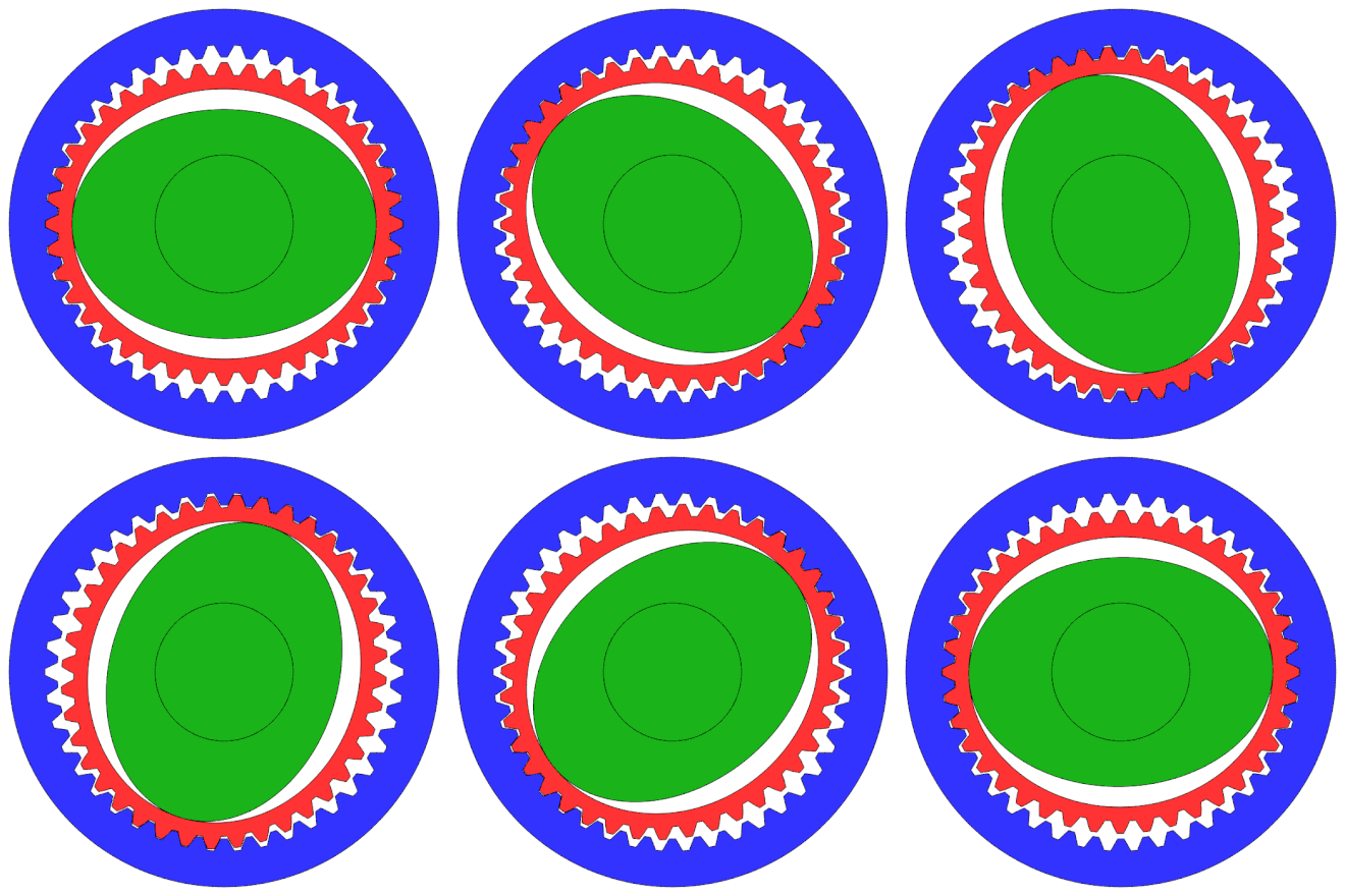
For my latest crazy project, I've been experimenting machining a homemade harmonic drive, and I thought I'd share my progress with you all. For those saying 'harmonic wha?', they're very simple devices which produce high ratio, zero backlash gear reductions in a very tight package, however they're potentially difficult to make (reflected by their crazy price tags).
Through my searches I've been unable to find any homemade examples apart from a couple of 3D printed ones which have limited use due to their low strength, so we may be in uncharted territory!
The biggest challenge is producing the teeth on the flexspine and circular spine, these need to match precisely, and the circular spine has internal teeth so that pretty much leaves us with broaching as the only option. For the broaching tool we need something very tough and precision ground, as luck would have it there's an easy source of these - carbide lathe inserts! The combination of insert you use dictates the number of teeth required to get perfect meshing, given by 360/(A - B), where A and B are the insert angles. Below is a list of the tooth count in the circular spine for each combination...
Attachment 356322
I figured a sharper tooth angle would be best, as it would reduce the radial loading when the unit is under torque, which could result in slipping teeth. In the end I settled for DCGT11 (55°) and TCGT16 (60°) inserts, which dictates 72 teeth on the circular spine, and 70 teeth on the flex spine, giving a gear ratio of 1:36. I machined up a couple of insert holders for the mill, and also machined up a spindle collar to stop the spindle rotating which also relieves the loads on the spindle bearings. I quick trial showed great success, I managed to broach teeth 4mm deep in aluminium with no problems, I also tried steel but chipped the insert at about 2mm depth (I was using an aluminium carbide insert).
Attachment 356342 Attachment 356344
Next up I turned a lump of aluminium to the correct external profile, and mounted it in the 4th axis which was placed vertical on the mill table. The program was simple, broach in 0.1mm steps with a spring pass at the end, rotate the table one tooth and repeat. The last step was to machine the bulk of material from the centre, which I left during broaching to minimise deflection, for the final pass I rotated the 4th axis to ensure it was perfectly concentric to the teeth. The circular spine was much the same deal.
Attachment 356332 Attachment 356334 Attachment 356336 Attachment 356338
Commercial harmonic drives use elliptical bearings for the wave generator, that's beyond this mere mortal, so instead I used a pair of opposing regular deep groove bearings. I don't think this is much of a compromise, and it allowed me to design in adjustability. The bearings were held in a pair of aluminium housings, the separation can be adjusted with an M4 screw, and a shaft attached to the back allows it to be connected to a motor.
Attachment 356328 Attachment 356330
I assembled it all together and a gave it a few turns, sure enough the circular spine slowly rotated around the flex spine, and I could not detect any backlash. Since this is a 1st prototype I thought I've give it a torture test, I hooked it up to a power drill and locked it in a vice, and ran it at about 2000rpm. After about 5 minutes, the flex shaft started to fracture at the teeth roots, not exactly suprising as it's an aluminium prototype! There was also some brinelling from the bearings on the flex spine, again not surprising. The teeth themselves were in good nick though, no signs of wear.
Attachment 356324 Attachment 356326
So overall I'd consider it a success, I'm already thinking about the Mk2, improvements I'm looking into...
- Steel flex spine (not sure what grade - suggestions??)
- Brass circular spine (to minimise wear/friction)
- Tweaks to the flex spine geometry (to reduce stress)
- Larger diameter flex spine (for higher load capacity)
- Needle rollers instead of deep groove bearings (to reduce brinelling)
- Redesigned bearing housing (easier to assemble and adjust)
- Helical motor coupling
As always, I'd love to hear anyone's thoughts or suggestions
Thread: Harmonic Drive - Mk1!
Results 1 to 2 of 2
-
03-25-2017, 11:00 PM #1
 Registered
- Join Date
- Jun 2008
- Posts
- 49
Harmonic Drive - Mk1!
-
03-25-2017, 11:28 PM #2
 Registered
- Join Date
- Jun 2008
- Posts
- 49
Re: Harmonic Drive - Mk1!
A few CAD screenshots...
Attachment 356360 Attachment 356362
I also did a very rough FEA to verify the teeth wouldn't bind...
Attachment 356356 Attachment 356358
Similar Threads
-
DIY Harmonic Drive
By drakke in forum Mechanical Calculations/Engineering DesignReplies: 8Last Post: 10-27-2015, 06:42 AM -
Harmonic drive help
By irishjam in forum DIY CNC Router Table MachinesReplies: 8Last Post: 01-01-2012, 10:46 PM -
Harmonic drive experts....help please
By HereinCS in forum DIY CNC Router Table MachinesReplies: 13Last Post: 03-02-2011, 10:11 PM -
Is this a harmonic drive?
By HereinCS in forum DIY CNC Router Table MachinesReplies: 4Last Post: 02-14-2011, 08:06 PM -
Harmonic Drive
By juzwuz in forum Mechanical Calculations/Engineering DesignReplies: 13Last Post: 12-03-2005, 08:28 AM


 Reply With Quote

