


Hi All,
I had these parts milled by a company. As the cost is high when someone is doing it. I thought I will do it myself. So currently in the process of getting myself a cnc mill.
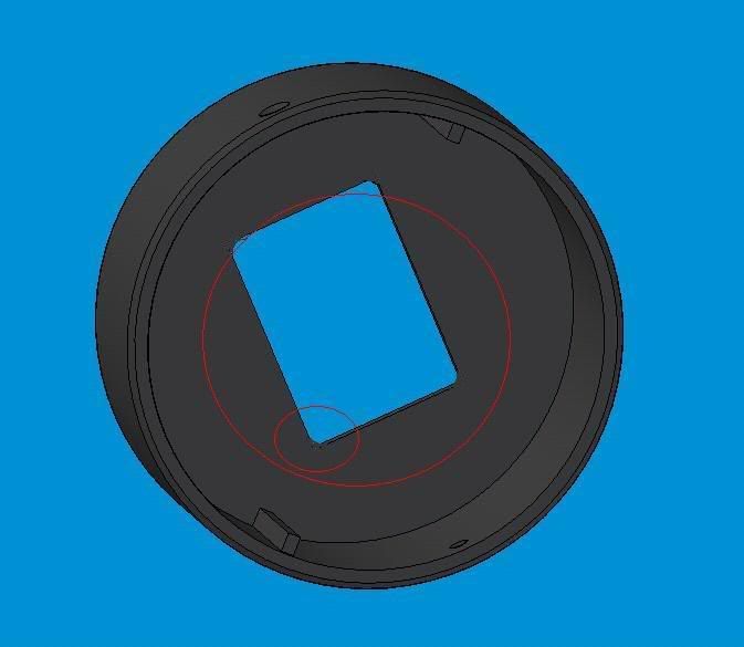
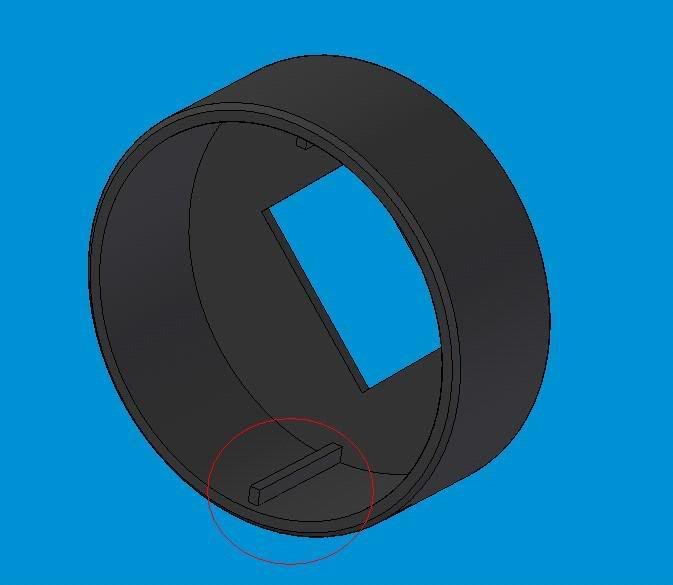
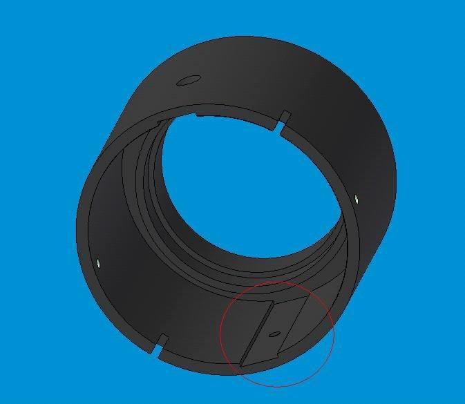
I have a few questions as to how some of the parts are milled? If you look at the photos, circled red are the recess and protruding parts that I am curious as to how they actually milled it. Its 90 degrees so I don't see how they can use an endmill to mill it without having some curve chamfers. Can anyone advised?
Thanks in advance.
Thread: How to make these parts?
Results 1 to 20 of 33
-
03-06-2007, 04:09 PM #1
 Registered
- Join Date
- Feb 2007
- Posts
- 632
How to make these parts?
-
03-06-2007, 04:43 PM #2
Gold Member
- Join Date
- Jun 2003
- Posts
- 2103
Broach or edm and I don't think you can broach a blind hole. I am not a machinist but have been around a lot of it. You have your work cut out making these with just one machine. I'd be willing to wager that the price you paid for them will not look nearly so high when you get through with the process of making them yourself!
 Ask me how I know!!!!(nuts)
MikeNo greater love can a man have than this, that he give his life for a friend.
-
03-06-2007, 04:57 PM #3
Registered
- Join Date
- Feb 2007
- Posts
- 632
Hi Mike, Thanks for the quick response. I know its not going to be easy to do this after reading some of the threads here. When you say the part may need to be milled with a few machines, what are the other machineries that the fabricator may have used to do this? Originally Posted by turmite

I might not be bothered to mill this out eventually and let the expert do it but knowing how its done would really help me to understand more about milling.
Its so funny that the fabricator informed me before fabricating the part that they couldn't do a perfect rectangular hole for me as shown in the model. So what they ended up doing was giving me a rectangular hole with curve chamfer on all four corners. Now I know how they made that. By using an endmill right? So if they can't do a perfect rectangle or square, how come they could do a perfect 90 degree recess and a protrusion?
I will probably ask them personally but if anyone can offer me an answer here. that will be great. I doubt very much if they would want to tell me so mcuh info on this seeing its their business.
Here is the picture I mentioned about the square hole.

They ended up giving me this instead.
Thanks
-
03-06-2007, 05:25 PM #4
Moderator
- Join Date
- Sep 2005
- Posts
- 1660
So your building a cnc mill to make this part? I'd think you should have looked at EDM, I don't think you'll find that you can make these on a mill, that is unless they are huge, and you have a teeny 5 axis head to reach inside there and cut them. 90deg corners on a milled part like that is pretty much outta the question..
JerryJerryFlyGuy
The more I know... the more I realize I don't
(Note: The opinions expressed in this post are my own and are not necessarily those of CNCzone and its management)
-
03-06-2007, 05:54 PM #5
Registered
- Join Date
- Aug 2006
- Posts
- 74
They probably did this in many pieces and then welded them.
-
03-06-2007, 07:24 PM #6
Monkeywrench Technician
- Join Date
- Jan 2004
- Posts
- 3154
Mill then EDM
www.integratedmechanical.ca
-
03-06-2007, 09:12 PM #7
Gold Member
- Join Date
- Jun 2003
- Posts
- 2103
I forgot to ask and made an assumption that this was metal. Is it metal or plastic? If plastic it would be injection molded, but the additional machines would still be needed. Originally Posted by alexccmeister
If the "square" hole had radiused corners it was milled. I would approach it by lathe and edm, for the part and a mill to make the electrode for the edm, so there is three machines.
Now where is HU when you need him?
MikeNo greater love can a man have than this, that he give his life for a friend.
-
03-06-2007, 09:15 PM #8
Registered
- Join Date
- Mar 2007
- Posts
- 6
making part
This part could be made on a mazak integrex and you could do internal hobbing or broaching to make internal parts but this is a expensive machine around 300,000.00 for a small one
-
03-06-2007, 11:38 PM #9
Registered
- Join Date
- Feb 2007
- Posts
- 632
Hi All,
Thanks for all your replies. The part is aluminium and the internal diameter is 70mm exactly. The thickness of the wall is 3mm. Well, the person informed me that the whole thing will be milled. She didn't mentioned anything about any other type of machine to do the job.
I would love to do this with a CNC machine of my own, but if its too difficult, I may need to redesign the parts taking account of the limitation of the cnc mill. Can a six axis machine do this part? I am sure their equipment is expensive, but unless their chuck or what evre is holding the endmill is small enough to get into a 70mm round space, I dont see how they can do it. I think EDM method may be the answer.So your building a cnc mill to make this part? I'd think you should have looked at EDM, I don't think you'll find that you can make these on a mill, that is unless they are huge, and you have a teeny 5 axis head to reach inside there and cut them. 90deg corners on a milled part like that is pretty much outta the question..
I am pretty sure this is milled as well. But that begs the question why they didn't do EDM on this part when they could do it on the most difficult part. I don't get it. They specifically told me they can't do it when I ask if they can give me sharp corners. Not that they won't do it as the square corner isn't that critical and I can live with round corners. They just can't.If the "square" hole had radiused corners it was milled. I would approach it by lathe and edm, for the part and a mill to make the electrode for the edm, so there is three machines.
I am not so sure as the part is really smooth and nicely done, no indication of any welded joints. I am convinced it is milled from a solid block of aluminium.They probably did this in many pieces and then welded them.
Thanks guys. I will put in an email to the fabricator and see if they can offer an answer. If they do, I will post the answer here. Thanks.
-
03-07-2007, 12:43 AM #10
Registered
- Join Date
- May 2003
- Posts
- 550
Interesting looking part - what does it do?
I have to ask; Does the function of the part *need* the difficult to machine elements as designed? Could you make the part easier to machine by including radius to allow simple milling?
Too often a part gets designed by people without much machine room experience and the part is unnecessarily hard or expensive to produce...
-
03-07-2007, 12:51 AM #11
Registered
- Join Date
- Feb 2007
- Posts
- 664
to make this part you will need to
mill ,broach and or scrape
or cast then finish with machining process
or forged then finish with machining process
or precision cast to finish
-
03-07-2007, 01:27 AM #12
Registered
- Join Date
- Feb 2007
- Posts
- 632
I have just emailed the fabricator regarding this issue. Will see what they have to say.
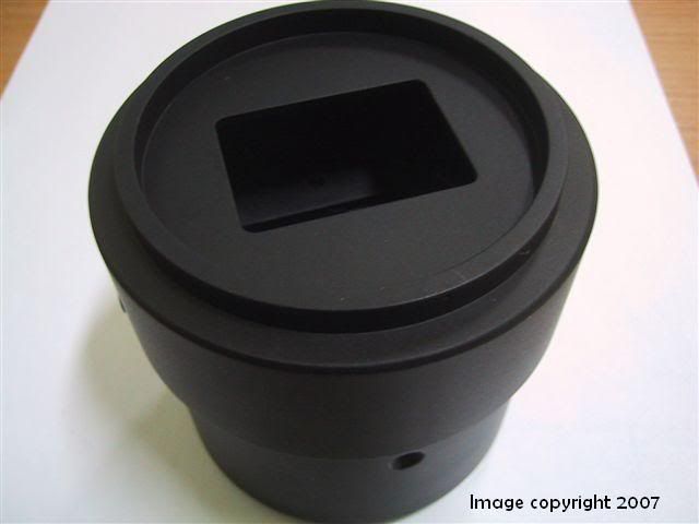
Its part of an imaging device I am working on. The prototype is already done by the fabricator. real; professional. Cost me a bomb having it made by a third party. So planning on getting some of the parts done myself. Here's the part after it was made, polished and anodised.Interesting looking part - what does it do?
I have to ask; Does the function of the part *need* the difficult to machine elements as designed? Could you make the part easier to machine by including radius to allow simple milling?
Too often a part gets designed by people without much machine room experience and the part is unnecessarily hard or expensive to produce...
Reply With Quote
I could probably just have the mill cut the piece out but with the curve chamfer instead of a 90 degree corner. Probably a very small end mill will do the job to finish off the corner portion?
-
03-07-2007, 02:54 AM #13
Registered
- Join Date
- Mar 2007
- Posts
- 8
The removal of material in the blind hole can be done by broaching using a single tooth custom broaching tool...I have done similar jobs in aluminum by mounting the part in a lathe chuck, locking the chuck solid with a brake/wedge/strap. The tool is mounted on the tool post and centered in the part using shims, and the cross slide is used to for depth of cut, the carriage is used by hand as the ram for broach. Set up a stop on the carriage just shy of the end a few thou so the chip dont break the tool. You can hand grind the tool out of square tool steel blank starting with a minimal relief angle. ...couple degrees...if u get chatter of deflection increase it a bit till its right. If you use too much it will dig in much like a chisel. Use WD 40. The part that extends into the ID can be done by machining and the broach can also be used to square up the radius thats left. I am not sure what the accuracy needed is...the tool can be made to size, or the chuck can be indexed a bit on an undersize tool with a small sacrifice of angle on the edge. Hope this helps.
Emmery
"Quit complainin, I wanna see chips'
-
03-07-2007, 06:13 AM #14
Registered
- Join Date
- Feb 2007
- Posts
- 632
Hi Guys,
Got the reply from the fabricator,
Looks like they used the broach method of getting rid of the chamfer. A really good job I must admit but I guess i can cut cost by not doing it this way. Will redesign the part so it can be easily milled.Dear Alex,
Nice to hear from you.
CNC is unable to achieve 90 degrees angle as the cutter are all round. So there will definitely be radius and the degree of radius depends on the cutter that is used. For Pic 1, the circled area had actually been manually polished after machining. Slight polishing was done to ensure there is no problem with fitting. This is why the corners appeared to be 90 degrees. For the rectangular hole in Pic 3, no polishing was done. Hence, the raw radius is more visible.
Hope the above clarifies
-
03-07-2007, 06:16 AM #15
Registered
- Join Date
- Feb 2007
- Posts
- 632
HI Emmery, Originally Posted by nupeswv
Thanks for the method of fabricating. Looks like the same method was used. So at least I know they didn't use a 300k machine to do the job. Just your everyday hand filing works.
-
03-07-2007, 02:03 PM #16
Registered
- Join Date
- Mar 2005
- Posts
- 1136
I've done the same, but in a blind hole? standard practice with a shaper would be to drill a hole at the end of the flat so the tool doesn't slam into the shoulder with no place to go. broaching in the lathe or mill is similar challenge if its blind. then again the old timers would have just had at it with a chisel and hammer, so a lot is possible with simple tools. Originally Posted by nupeswv
Alex i think you've come to the right conclusion, redesign the part. This is why its so valuable that designers also understand machining and imo where disdain between machinists and engineers comes from.
whats a bomb btw? its all relative, but its a big assumption that you can bring it in house and save money. If the outsourced supplier was selected in a competitive environment, and his price is based on the cost of his equipment, tooling and time, you are going to incur the same costs or more given you may not be as efficient as the specialist.
for production, would plastic work? i don't know loads or tolerances but the part could easily be injection molded.
-
03-07-2007, 02:41 PM #17
Registered
- Join Date
- Feb 2007
- Posts
- 632
Hi Mcgyver,
Your suggestion is a lot work me and I will probably not see myself slaving away filing and polishing the parts after being CNCed. So redesign it is.
"bomb" is just a figure of speech I use when something is expensive. I haven't decided what I will do as far as the part fabrication are concern. But once my cnc mill is here and all set up, i will be doing some fabrication myself to see how much I can do. It probably won't be as good as the expert, but if I don't try I wouldn't know. As there are many parts that I need to fabricate out of both plastic and metal, I may just do some of the simple parts and leave the rest to the expert and cut cost there.
The other reason why I would want to do it myself is that the parts I am doing are in the early stage of the design and the one that was made by the expert was a prototype. Still need some more testing before I finalise the design. So the parts I need made are costly and although not as costly as a new set of cnc mill, I will be spending quite a bit having them made and they won't necessary work. So its back to the drawing board redesigning and going back to the expert . Very troublesome, so why not get a cnc mill and I can test all i like until i get it right. I gain experience and a set of cnc mills. Oh! and the nearest cnc milling company to me is by a plane ride that takes 2 hours to get there. So that too was a deciding factor for me to go with my own CNC mill.
I have thought about plastic injection molding. But I can't source for the right equipment where I live and most of the parts are in aluminium anyway.
Thanks.
-
03-07-2007, 07:12 PM #18
Registered
- Join Date
- Mar 2007
- Posts
- 8
I did not have a problem doing blind hole in aluminum with broach but solved the problem on a steel part by using a small woodruff cutter to cut a 1/8 " wide crescent shaped relief at the end of the groove. The tool and chip can run out there without worry of breaking tool. It also does not show as a hole on the exterior of the part if cosmetics are a concern. The job can be simplified also by running the woodruff cutter down the groove to remove most of the material to proper depth, mark with magic marker and use the broach tool to just clean up the rads in the edges till mark is gone. The cutter needs to be of the offset side cutting variety.
-
03-07-2007, 07:38 PM #19
Gold Member
- Join Date
- Dec 2004
- Posts
- 524
In doing your re-design consider:
which aspects of the design are functional
which parts of the design are esthetic
which parts of the part are visible
An example: I had a part that had a rectangular LED display passing through the aluminum housing. Since the corners of the LED had a small radius, it was not cost effective to cut a rectangular hole. Instead, I made a hole with 'dog ears'. I let the cutter run past the corner by an amount equal to the radius and then back up before doing the adjacent side. Since there was an overlay covering the hole, the end user couldn't see the funny looking hole and I could just mill it without any secondary operations.
Keep us informed as you go through the redesign. I'd be interested in seeing the next few iterations.
As a reference, I went through at least ten different designs on the manifold of the anesthesia machine we sell. And that doesn't count the designs that were just on paper.
KenKenneth Lerman
55 Main Street
Newtown, CT 06470
-
03-07-2007, 11:37 PM #20
Registered
- Join Date
- Feb 2007
- Posts
- 15
Looks like a milled casting.
Just another chip in the pile.
aaron

 Reply With Quote
Similar Threads
-
New eStore Added to AAC Vibration Mounts Web Site to Make it Easier to Order Parts
By carolpratt in forum News AnnouncementsReplies: 1Last Post: 05-31-2010, 09:05 AM -
How would you make this?
By Art Ransom in forum Wood Lathes / MillsReplies: 5Last Post: 01-09-2007, 01:03 PM -
trying to make a die.
By Dougotio in forum Diemaking / DiecuttingReplies: 9Last Post: 04-08-2006, 11:37 PM -
Mini Mill to make camera parts
By Moesian in forum Benchtop MachinesReplies: 1Last Post: 04-17-2005, 04:40 PM -
How can I make
By cncman in forum CNC Machine Related ElectronicsReplies: 3Last Post: 03-23-2004, 08:49 PM
