


I have been lurking around here for some time now and have started to build my own CNC router.
I didnt find any plans that really fit my needs. (Mainly the amount of Cutting area I want)
So I have been messing around with my own design for a while now, and am now starting to build it.
I am planning to use Gecko G201's for all axis's, 600+ oz-in nema 34 motors, and Nook rolled ballscrews.
The X and Y axis are using 20mm supported rails with 6 bearings for the X and 4 for the Y.
The Z axis will use supported 1/2" rails and 4 bearings.
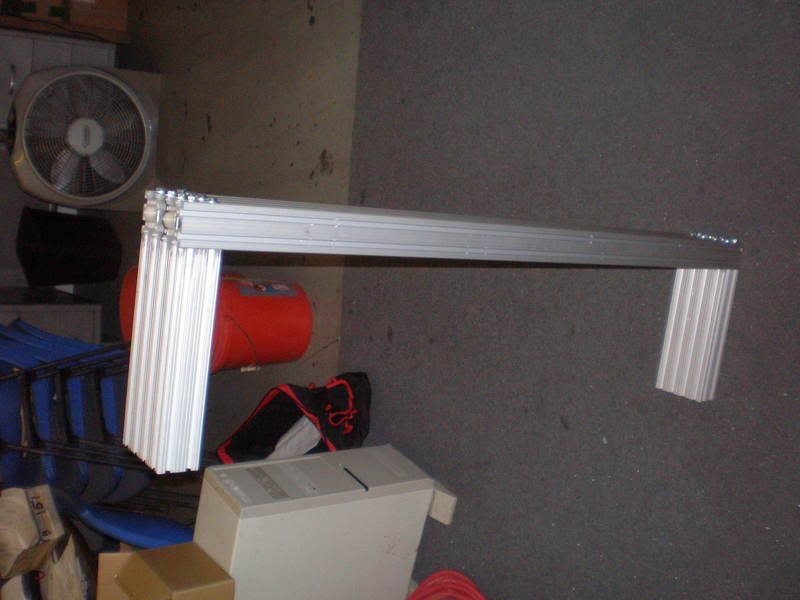
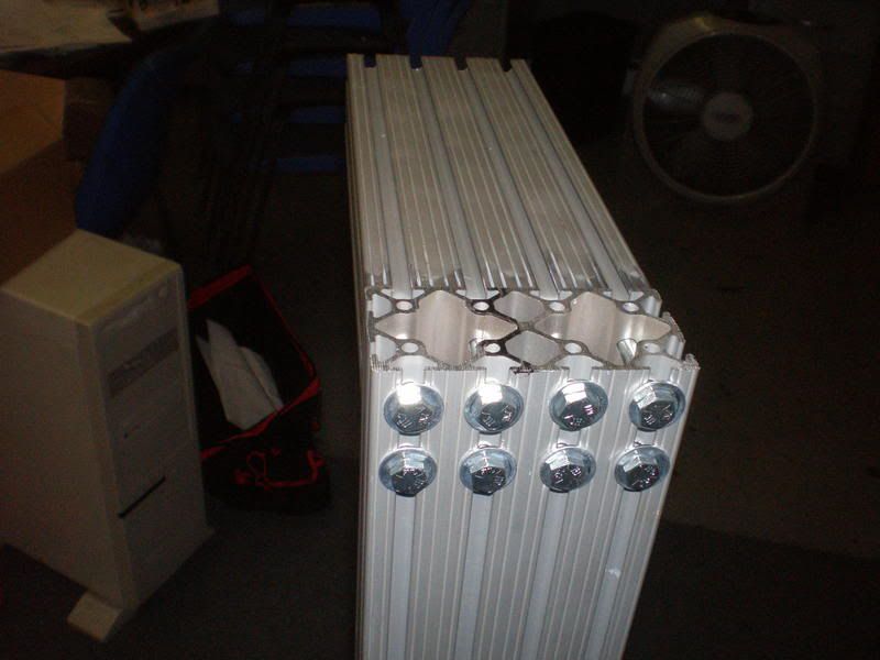
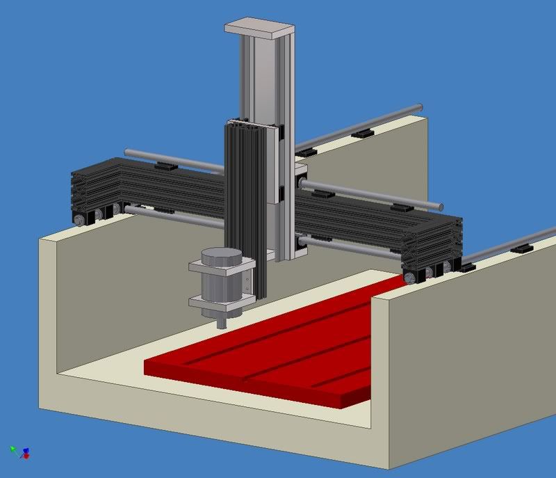
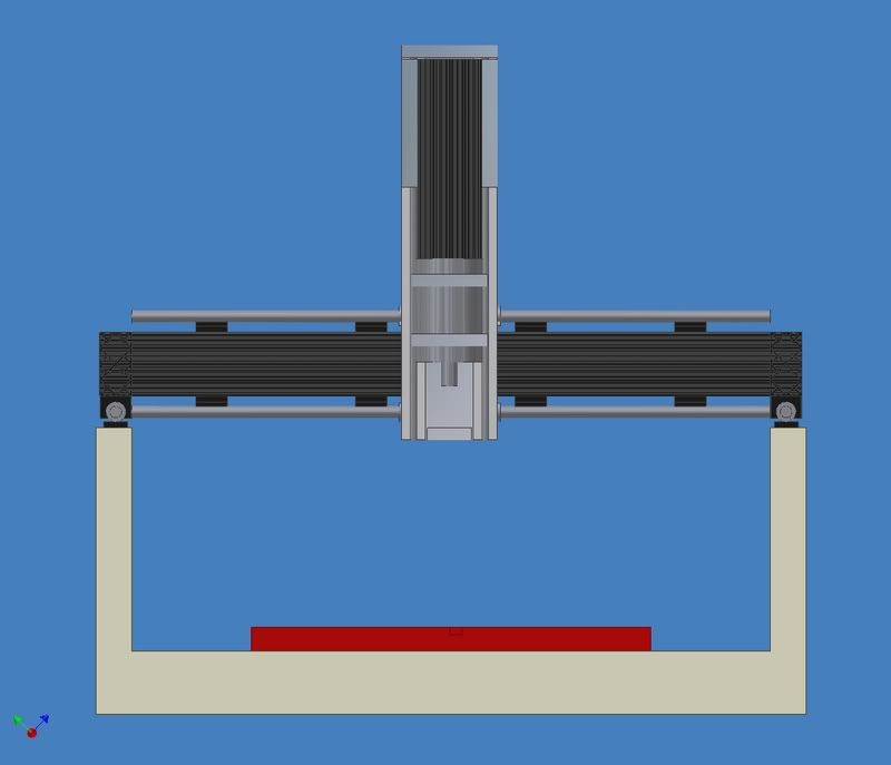
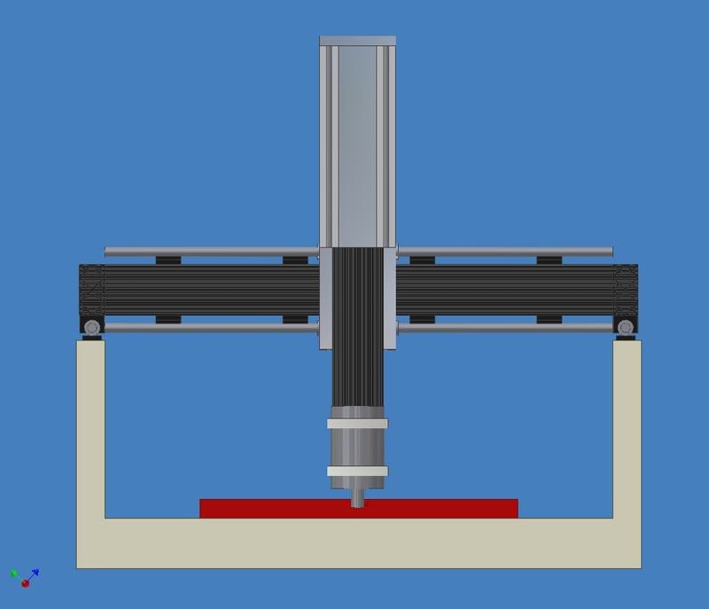
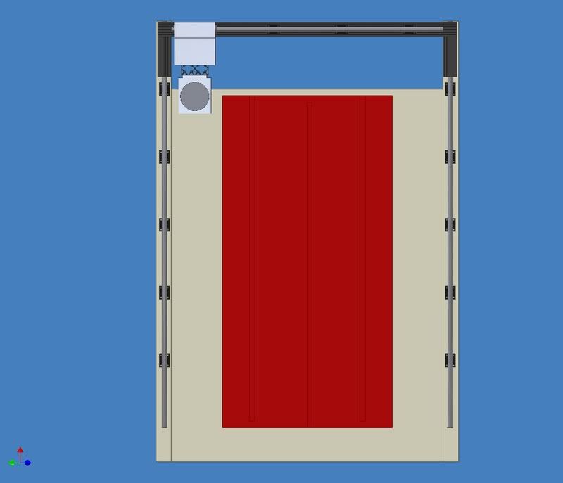
The whole moving structure will be made out of 2" x 4" 8020 and 3/4" aluminum plate.
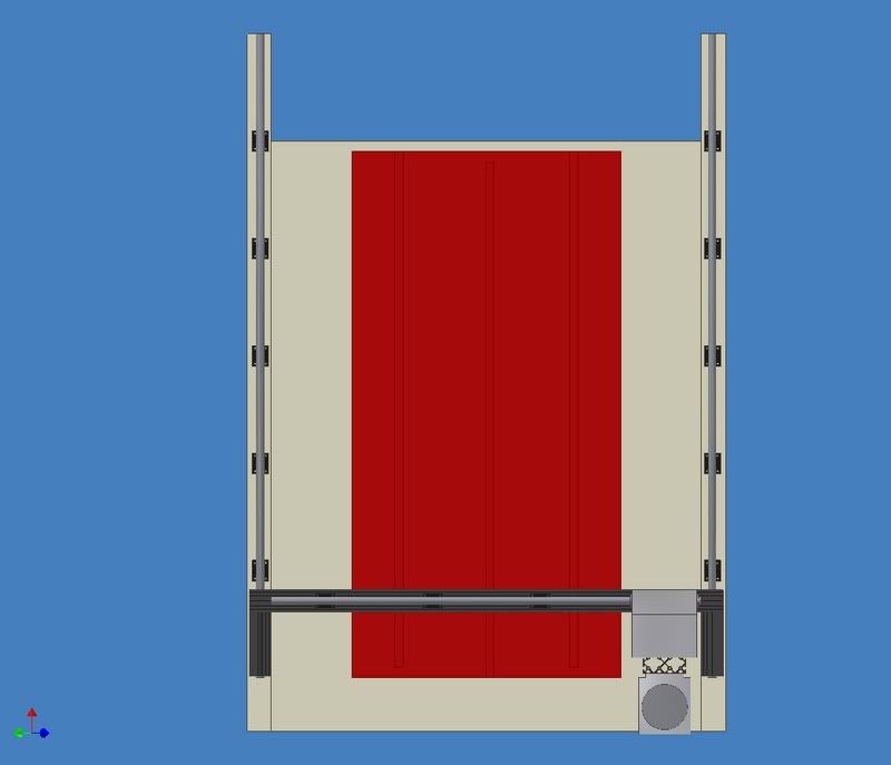
i estimate the travel of the finished unit to be around 50-51" on the X, 32-34" on the Y, and somewhere between 13" and 16" on the Z (in the pictures it is about 16"
for some scale, the red piece is 25" x 49" x 1.5"
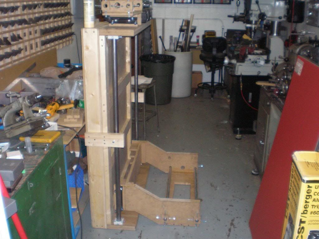
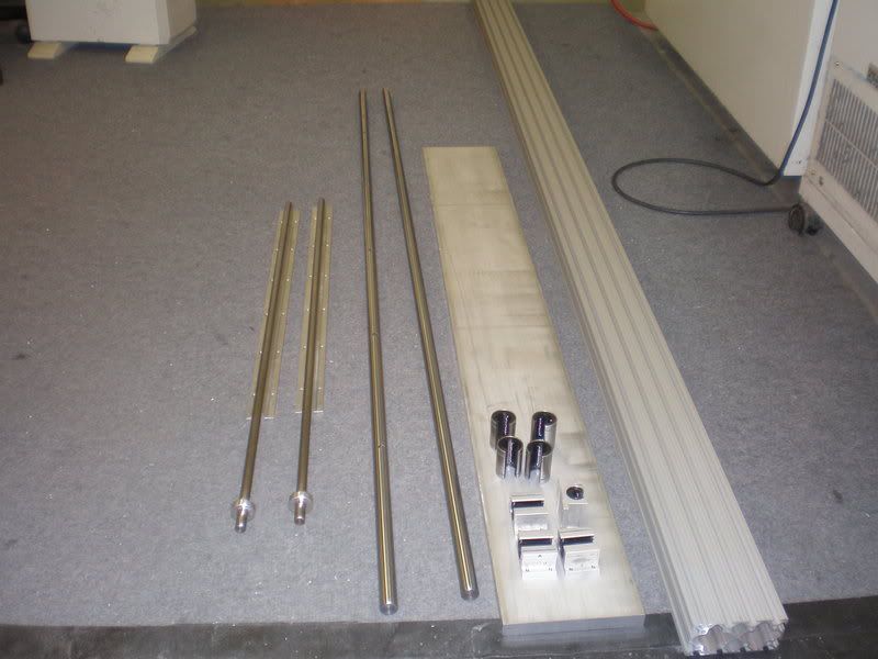
here are some pictures of what i have so far, everything is there except the screws/motors since i havent figured out exactly where i want them placed.
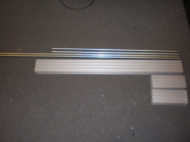
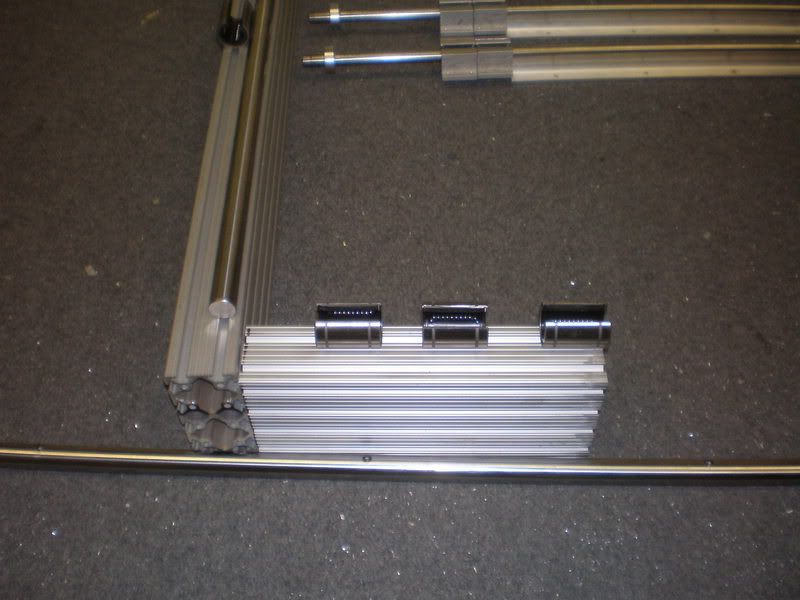
the y and z rails, and the aluminum stock. (Not Pictured, 2 more 20mm rails and 6 more bearings)
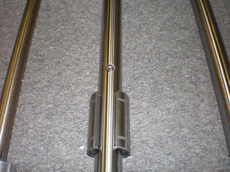
Y rail with bearing
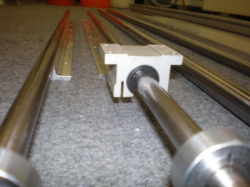
Z rail with bearing block
The mounting blocks for the Y bearings (still need to be wire edm'd)
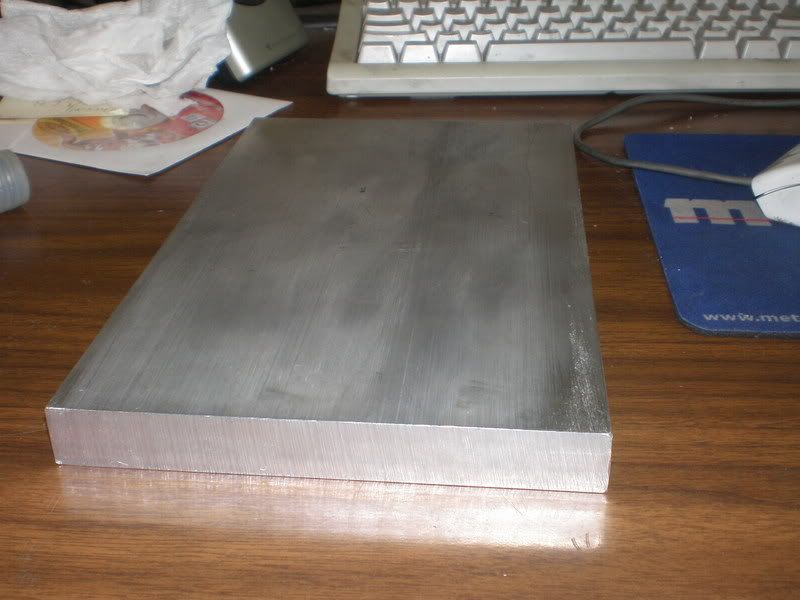
A piece of 3/4" plate for the x/y support blocks.
SEE POST 13 FOR MORE PICTURES OF THIS.
here are a couple pictures of how i think it will look.
my main question is on driving the X axis, I really want to avoid having to use 2 seperate motor/driver/screws to drive it, since that would add another $300 to the already expensive machine.
And there is no good way to drive it from the center.
Would it be okay to drive it from just one side if evrything is nice and solid?
that is part of the reason i went with 3 bearings per side on the x, and they are spaced out to cover 8" so that should help a bit.
I will be adding some bracing to the y axis to strengthen it some more and holefully prevent racking/binding.
And with 5/8" nook rolled ballscrews will a 64ish" span be okay?
i will be doing the largest part of my cutting towards the center of the x travel, so they will be supported by that most of the time.
any and all comments/suggestions are welcome.
Thanks,
~Magick_Man~
Results 1 to 20 of 52
-
04-07-2007, 05:20 AM #1
 Registered
- Join Date
- Nov 2006
- Posts
- 51
New machine in the works. Plenty of pictures.
-
04-07-2007, 11:19 AM #2
Member
- Join Date
- Dec 2004
- Posts
- 1316
Looks pretty good. The Z axis will have lots of travel.
To easily get the X axis driven from both sides, cogs can be attached to the lead screws on each side of the X axis with a belt running between them.
Jason
-
04-07-2007, 12:42 PM #3
Registered
- Join Date
- Mar 2005
- Posts
- 1673
Hi,
Interesting design.
The answer about the X axis screw/s will depend on how much cutting force you are expecting at your spindle. So will depend on materials to be cut, feed speeds, cutter type and geometry and depths of cut.
Is the planned use of this machine going to be timber only, timber and some aluminium, both or other?
Sorry if I missed it but what are you using for the machine base/sides?
John
-
04-07-2007, 04:29 PM #4
Registered
- Join Date
- Nov 2006
- Posts
- 51
Yeah, I want to be able to do some relatively large 3d models so I needed quite a bit of z travel. Originally Posted by Jason Marsha

And I think I might have to go to a belt drive for the x axis to easily drive it from both sides.
Originally Posted by Oldmanandhistoy
It's main use is going to be shaping/cutting MDF and other woods, But I want to be able to do some aluminum and copper every now and then also.
The main base will be made of a mdf/2x4 torsion box that I already have built from a previous try at a jgro type machine.
And the sides will be made of 3 layers of 3/4" mdf.
I dont imagine i will have a problem with the side panels flexing since they will 2.25" thick.
But I will find out when I start to put it together.
~Magick_Man~
-
04-07-2007, 06:30 PM #5
Registered
- Join Date
- Mar 2005
- Posts
- 1673
MDF does not require that much cutting force (depending on cutting depth and size of tool). As for aluminium; I recall reading some where that using a ¼ “end mill with a 1/8 “ depth of cut at around 20 ipm would require approximately 25 lb force on the tool tip (do not quote me on this and it may be worth your while getting a second opinion). So if you could fix one side of your gantry, put the Z axis to its opposite side limit, then put 25 lb + force on your spindle colet and then measure the movement of the none fixed side of your gantry it will give you a good idea to whether you need the second screw. Originally Posted by magick_man
If you do use two screws with belt drive are you planning to direct drive one of the screws with the stepper and take a belt to the other screw? Or fix the stepper in the centre of the two screws then take belts to each screw?
If you plan to direct drive one of the screws from the stepper; if it were me and the deflection test was in a reasonable amount I would go with one screw and see how it goes. If the gantry racked too much in use I would then add the second screw.
Hope this helps and good luck with your build,
John
-
04-07-2007, 10:54 PM #6
*Registered User*
- Join Date
- Feb 2007
- Posts
- 2
Where do you get the "T" slot aluminum bar stock from?
Great design! I've been lurking here for quite a while and stumbled on this thread. I'll be building a cnc machine of my own soon that is very similar to your design. What is that "T" slotted aluminum bar called and where do you get it from. I would like to use it as a table top/hold down table.
I've attached a pic to explain what I mean.
Thanks
Kelvin
-
04-07-2007, 11:27 PM #7
Registered
- Join Date
- Nov 2006
- Posts
- 51
I guess I will have to wait till I get the machine mostly built and test for racking before deciding how I want to drive it. Originally Posted by Oldmanandhistoy
Right now I am looking at 600 or maybe 960 oz-in RS steppers from homeshopcnc.
If I go with the 600's I will probably direct drive the ballscrews for all axis's (if I stick with the ballscrews)
But if I go up to the 960 (which I probably will on the x and y) I will gear them to bring up the speed of the motors since I will have plenty of torque at my disposal.
And to answer your questions if I go with belts I will just use the belts to drive the axis, and not use leadscrews/ballscrews
Now I almost wish I could find 72" tapped rails (Instead of the 60" I have) for the X axis, Then I could spread out my X bearings alot more and still get the travel I want.
Originally Posted by kavic
I purchased it on ebay from a company called 80/20.
There are banners for 80/20 on this site all the time.
So if you click on one of those it will take you to their ebay store.
That particular one is called 2040, It is 2" thick by 4" wide.
But they make some thae are thinner and wider that would be better for a table top.
~Magick_Man~
-
04-09-2007, 07:48 PM #8
Registered
- Join Date
- Nov 2006
- Posts
- 51
Question, would it be better for me to extend the side pieces on my y axis so that my bearings are in line with the router like shown in the picture below.
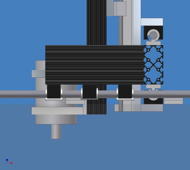
the way i have them right now the side piece is a bit shorter and the router sticks out past where the bearings are.
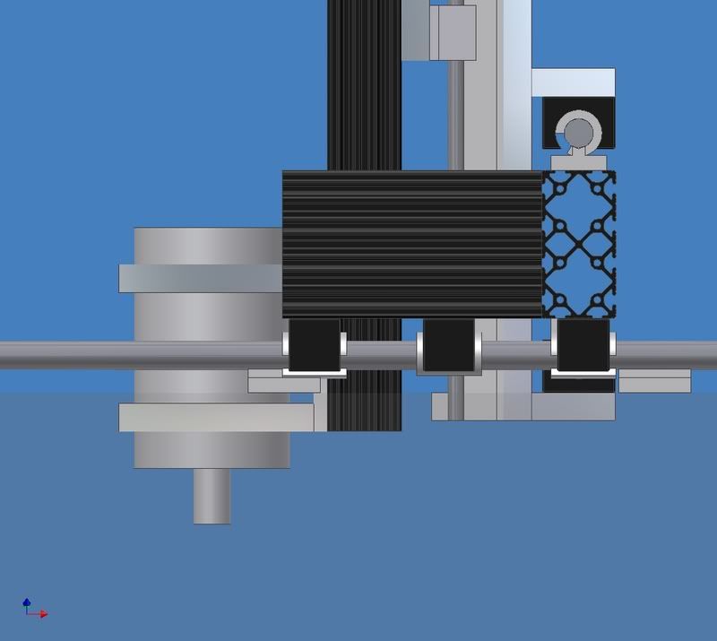
would it really gain me anything?
i can explain it a bit better if that is confusing.
Thanks,
~Magick_Man~
-
04-09-2007, 09:35 PM #9
Registered
- Join Date
- Mar 2005
- Posts
- 1673
Hi again,
In my opinion the further you have the bearings apart the more rigidity you will have in your gantry.
The first picture with the bearings inline with the spindle is the way to go; it will decrease the lever effect from your spindle on the x axis.
Just my opinion,
John
-
04-09-2007, 10:47 PM #10
Registered
- Join Date
- Mar 2007
- Posts
- 38
Mr. magick-
Nice design. :rainfro:
So nice in fact that you're forcing a small redesign of mine.
I had intended to go with something like in the attached but think now that raising the X-axis up would be better.
To reduce both flex and nasties getting into the bearings.
Actually, probably be a complete overhaul.
Thanks for that.
And thanks for the idea.
And keep us posted.
Greg
-
04-09-2007, 10:55 PM #11
Registered
- Join Date
- Feb 2007
- Posts
- 27
Magick_Man
What cad program are you using that produced your drawing?
Thanks
Nils
-
04-09-2007, 11:15 PM #12
Registered
- Join Date
- Nov 2006
- Posts
- 51
I think I am going to end up with 8-8.5 inches for the bearings, That is about the max I can use and still get my 50" travel on the x axis. Originally Posted by Oldmanandhistoy
And I think you are right, The first one seems that it will be a bit better.
Hopefully I will have enough of the 8020 extrusion to make them that long:stickpoke
And also thanks for your continued input.
Any little thing I can do to help Originally Posted by 11bravo

Originally Posted by sailfl
The program I am using is Autodesk Inventor 7
~Magick_Man~
-
04-11-2007, 02:19 AM #13
Registered
- Join Date
- Nov 2006
- Posts
- 51
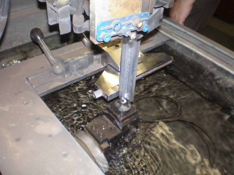
Well I finally got the pictures off my camera.
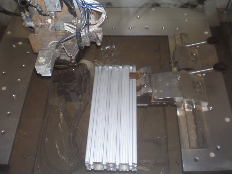
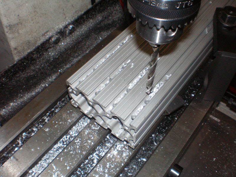
So here are some pictures of the support blocks I made for the x and y axis.
In the edm ready to be cut into smaller pieces.
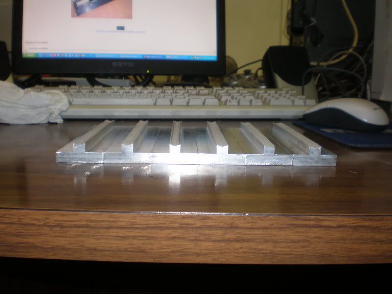
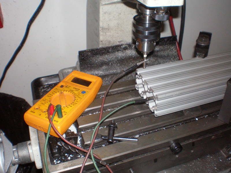
One of the 1.5" wide strips cut from the larger block ready to have the V groove cut into it.
The 6 1.5" strips with the V groove cut into them.
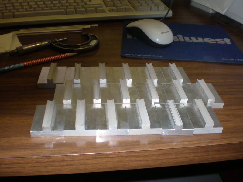
And finally 18 separate support blocks cut from the 6" long strips.
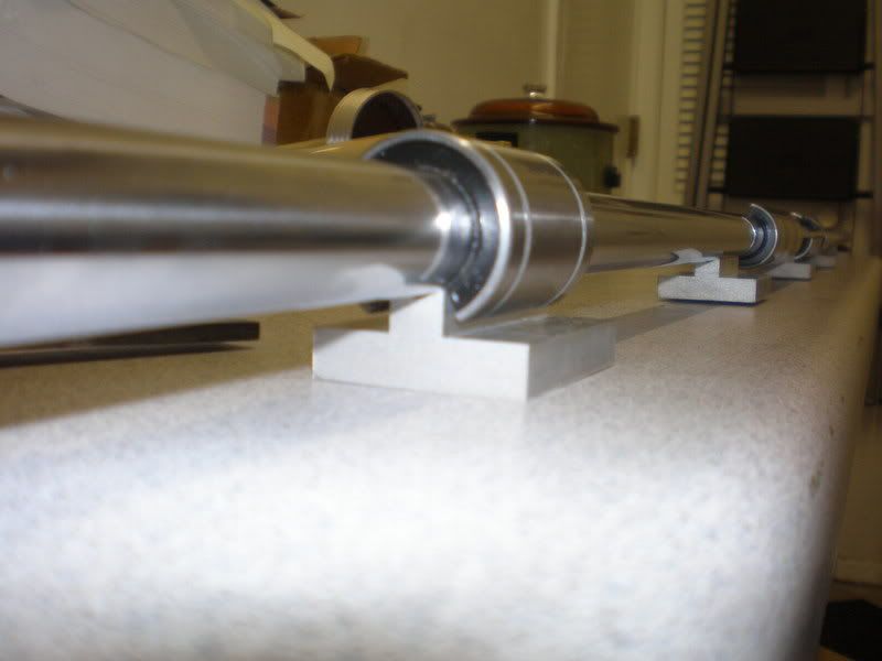
One of the 60" rails with 5 support blocks mounted on it.
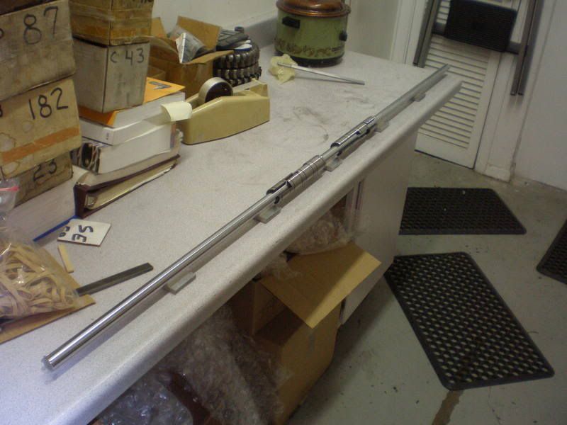
Not a very good picture, But you can see how the bearing clears it.
Hopefully i will make some progress on the base of the machine this week.
~Magick_Man~
-
04-11-2007, 10:03 AM #14
Registered
- Join Date
- Nov 2006
- Posts
- 296
Niiiiice, supported rails, that's the way to go, i think i like what i'm seeing, i'll be watching your progress from here on.
-
04-11-2007, 10:05 AM #15
Registered
- Join Date
- Nov 2006
- Posts
- 296
Drat, double post, browser glitch, sorry.
-
04-11-2007, 01:07 PM #16
Registered
- Join Date
- Nov 2006
- Posts
- 51
Thanks, I looked at unsupported rails first and they just wouldn't cut it for what i want. Originally Posted by tajord
Especially for my 60" long x axis.
~Magick_Man~
-
04-13-2007, 05:25 AM #17
Registered
- Join Date
- Nov 2006
- Posts
- 51
Well I have gotten a bit done on the machine.
The y rails are cut to size, And so are the extrusion pieces for the yaxis.
I also got the 3 extrusion pieces for the y tapped and bolted together.
Hopefully tomorrow i can get the table sides built and attached.
The y rails and extrusion cut to length.
The short pieces for the y on the edm to make the ends nice and square.
My ghetto rigged edge finder.
Drilling the holes to bolt them together.
The y axis is all bolted together.
I went ahead and used the longer side pieces, so the bearings are in line with the router.
8 Bolts per side, I don't think this is coming apart any time soon.
Well that is pretty much it for now.
Hopefully tomorrow I will have some more done.
~Magick_Man~
-
04-13-2007, 05:42 AM #18
Registered
- Join Date
- Feb 2006
- Posts
- 1187
EDM, I,m impressed. Where do ya work? Its lookin sharp, looks like ya got a full machine shop to use.
-
04-13-2007, 05:46 AM #19
Registered
- Join Date
- Nov 2006
- Posts
- 51
Originally Posted by ZipSnipe
I work at a tool grinding shop in hurst tx.
We do alot of wire edm so luckily i get to run a part of my own through there every now and then
~Magick_Man~
-
04-13-2007, 07:29 AM #20
Registered
- Join Date
- Nov 2006
- Posts
- 51
i feel so unloved, nearly 700 views and only 7 people have replied

:stickpoke
~Magick_Man~


 Reply With Quote
Similar Threads
-
G41 and G42 How are works ?
By bunalmis in forum G-Code ProgramingReplies: 25Last Post: 06-29-2018, 01:31 PM -
How does this works
By Syphonics in forum Mechanical Calculations/Engineering DesignReplies: 18Last Post: 03-01-2007, 03:59 PM -
Can someone tell me how this PIC works?
By KPyro in forum Stepper Motors / DrivesReplies: 10Last Post: 12-09-2006, 10:48 PM -
Gibbs & Machine Works
By cadman in forum GibbsCAMReplies: 5Last Post: 02-20-2004, 05:15 PM -
How does G 41, G42 works ?
By BanglaTech in forum Uncategorised CAM DiscussionReplies: 7Last Post: 11-04-2003, 06:38 PM
