


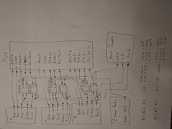
Sure, here are some pics of the wiring diagrams and the board I made to do the interfacing. The analog pairs don't go through the board but rather are direct connected. The EStop connection shown is to my EStop relay which for this item is wired normally open (E-Stop tripped) to digital ground. R1, R2, and R3 should be 200 - 1K ohms and R4, R5, and R6 should be 1K - 6K ohms. I used 1K for all 6. Ideally R4, R5, and R6 would be closer to 5K to reduce the current draw. Let me know if you have any other questions on this.Originally Posted by CATCH22

Attachment 421156
Attachment 421158
Results 1 to 20 of 27
Hybrid View
-
05-30-2019, 05:46 AM #1
 Registered
- Join Date
- Apr 2005
- Posts
- 72
Re: Setting up AMC BE25A20 in torque mode?
-
05-30-2019, 07:36 PM #2
Member
- Join Date
- Mar 2005
- Posts
- 271
Thanks Sean, now all I have to do is figure out how to read electrical schematics. Lol Originally Posted by seanano
-
05-30-2019, 07:38 PM #3
Member
- Join Date
- Mar 2005
- Posts
- 271
Hey Sean where did you get the stuff to make your own boards? Originally Posted by CATCH22
-
05-31-2019, 04:26 PM #4
Registered
- Join Date
- Apr 2005
- Posts
- 72
Re: Setting up AMC BE25A20 in torque mode?
Most of the parts I had left over from previous projects. The only thing I had to buy were the CPC1333G chips and I got those from DigiKey: Originally Posted by CATCH22
https://www.digikey.com/product-deta...388-ND/3077506
Mouser also has them. I tend to get most of my chips from those two places. The circuit board and terminals can be found in sets at a lot of different places including Amazon and eBay. I just bought a set off of Amazon for making my spindle encoder board:
https://www.amazon.com/gp/product/B07PD1HFHQ
I haven't actually used it yet so this is not an endorsement of that particular item. You can solder the CPC1333G chips directly to the board but I prefer to use IC sockets so they are easier to replace if necessary. A single 24 pin DIP socket is sufficient for this board. I had a couple of 14 pin sockets laying around so I used those with a gap between each pair of chips. You can find the sockets at DigiKey, Mouser, Amazon, or eBay. Depending upon where you live there may still be an actual electronics store locally that may have them.
For the resistors, 1/2 watt and pretty much any tolerance will work. Might as well get them from where you are getting the chips. Note that if you aren't using 24VDC for the 7i77 Field I/O then the resistor values may need to be changed.
As for reading the schematic, just follow the lines. Any big dots are junctions. Squiggly lines are resistors. The CPC1333G chip pins are labelled on one of the drawings. Pay attention to orientation. For each axis, I have the chips flipped 180 degrees since one chip is output from the 7i77 and the other chip is output from the AMC drive.
A disclaimer... I am not an electronics pro, just a hobbyist. I have only been using the board for about a month and it functions as I expected. Before you go through the effort of making this, do make sure your drives are functioning properly if you haven't done so already. Go through the drive setup section in the manual I referenced earlier as it walks you through this.
-
05-31-2019, 05:11 PM #5
Member
- Join Date
- Mar 2005
- Posts
- 271
Awesome, thanks Sean. Originally Posted by seanano
-
03-03-2020, 04:19 AM #6
Member
- Join Date
- Mar 2005
- Posts
- 271
Hi Sean, I am just starting to get back to it, just wondering if you have had a chance to try your boards out yet and if you have made any changes before I drive in. Originally Posted by seanano
Thanks Mike
-
03-03-2020, 04:16 PM #7
Member
- Join Date
- Mar 2005
- Posts
- 271
Hey Sean, could you also tell me what size boards you used. Originally Posted by CATCH22
Thanks Mike
-
04-02-2020, 05:34 PM #8
Member
- Join Date
- Mar 2005
- Posts
- 271
I made one of these boards that Sean so kindly shared with me, but I can't figure out where the fault goes into the 7i77 board, can't see anything in the manual about it. Originally Posted by CATCH22
If anyone can help me out I would really appreciate it.
Thanks Mike
-
05-20-2020, 02:52 PM #9
Registered
- Join Date
- Apr 2005
- Posts
- 72
Re: Setting up AMC BE25A20 in torque mode?
Mike, I apologize, I must have missed the notification there was a reply in the thread. Did you get this figured out yet? I have each of the fault outputs from the board going into one of the 7i77 24VDC capable inputs. It really doesn't matter which one. I have that input pin then set as a fault for the axis in the hal configuration (IIRC I did that in pncconf). I know that isn't real specific. I can go grab the configuration from the machine if it would help. Originally Posted by CATCH22
Sean
-
05-22-2020, 03:07 AM #10
Member
- Join Date
- Mar 2005
- Posts
- 271
Thanks Sean, but I have it up and running now. Originally Posted by seanano
Thanks Mike

 Reply With Quote
Similar Threads
-
What is - Torque Mode? Position Mode? Speed/Velocity Mode?
By sunmix in forum Servo Motors / DrivesReplies: 48Last Post: 01-20-2024, 10:34 AM -
Speed vs. Torque mode
By arvidj in forum Dynomotion/Kflop/KanalogReplies: 5Last Post: 06-17-2013, 03:55 AM -
Step Response graph in Torque Mode
By Dr.Nos in forum CNC Machine Related ElectronicsReplies: 2Last Post: 10-27-2012, 09:57 PM -
Torque Mode vs Velocity
By K&T EB in forum CamSoft ProductsReplies: 4Last Post: 01-06-2010, 03:40 PM -
AMC BE25A20 drive in encoder velocity mode.
By lucas in forum Servo Motors / DrivesReplies: 0Last Post: 04-02-2009, 06:58 PM
