


i build a brassy babe 2 wobbler engine a few months ago, and it ran great at anything over 45psi. i remade some parts and cleaned it up, and it would run for about 30 seconds at 15psi. then for some reason it just stopped and now wont run under about 30.
so i built a new one today, and it ran for a few minutes around 50psi, and now its realy stiff. so i was trying to polish the piston and cylinder and i broke off the piston in the cylinder.
so now onto the questions:
1. if i wanted to make one that could be run off of lung power, what would i have to change?
2. would it make a difference if the piston and cylinder were made form different materials. right now im using aluminum for everything?
3. would different types of oil/grease make a difference? im using 3 in 1 stuff right now, and its really thin and just runs off of everything.
thanks for the help.
Thread: Wobbler Questions
Results 1 to 13 of 13
-
06-04-2007, 11:18 PM #1
 Registered
- Join Date
- Dec 2006
- Posts
- 45
Wobbler Questions
-
06-05-2007, 01:54 AM #2
Registered
- Join Date
- Mar 2005
- Posts
- 1136
same materials make a poor bearing surface, but that is usually in the context of galling/wear, can't see it being a big factor in creating drag. use a very light oil, like instrument oil; haven't used 3in1 in ages but iirc its heavy. after that is matter of design, construction (everything square, no binding etc) and how tight or loose it is (clearance between mating parts). These little wobbler engines are not very efficient though, ie no matter how precisely you build it, there's a lot of friction between the cylinder and stand, held together by the spring, still you'd' think 10-15 psi would be more than enough. How freely does the engine turn over?
-
06-05-2007, 03:25 AM #3
Gold Member
- Join Date
- Jul 2005
- Posts
- 12177
Aluminum running against aluminum is not good, it can readily gall up and seize solid. Originally Posted by dragons_fire

Whenever you have two materials running against each other as in a sleeve bearing or a piston and cylinder they nearly always should be different. There are two exceptions that I know about:
One is brass, brass will run against brass very successfully and this also applies to some of the bronzes. In fact it is possible to run some brasses and bronzes against themselves even without lubrication and this was done in old clocks.
The other is cast iron, ductile or nodular cast iron which is what machine tool ways are made out of. Although with cast iron you do not really have two identical materials you have a mixture of materials; it is the graphite inclusions in the cast iron that permit it to slide with suitable lubrication without galling. Dry cast iron running against itself may gall and seize.
In general however, if you are making a bearing or a piston and cylinder, the best choice is a harder or stronger material running against a softer or weaker material.
But the weaker material should not be aluminum, it can gall and seize with almost any other metal. Some aluminum alloys are okay such as the ones used for cheap electric motors where the shaft runs directly in the alloy end housing but these are specialized diecasting alloys.
Notice that I say aluminum can gall up; it is not guaranteed that it will. It is possible to have aluminum running against aluminum with good lubrication, particularly a lithium or graphite grease and it might work for a very long time at light loads. But it is courting sudden failure to do this.An open mind is a virtue...so long as all the common sense has not leaked out.
-
06-05-2007, 05:06 AM #4
Registered
- Join Date
- Dec 2006
- Posts
- 45
so this second one that i made, has a bore of 5/16" and a stroke of around .4". i had it running for a couple minutes, and it completely seized up, and then when i tried to get it out, i broke the "con rod" off of the piston. i completely remade the piston and cylinder, polished them both and made it a little cleaner. it ran really nicely for a while, (i let it run for about an hour). it would idle around 11psi, and go really nicely on 16psi from my airbrush compressor. i think because i let it run for so long, it has loosened up so much that it wont run below about 15psi.
i enjoy turning aluminum and it seems more like a chore to machine any other metals I've tried. so on my next wobbler i may try other metals, but i will make whatever i can from aluminum.
so what about using aluminum for the piston (and maybe anodizing it) and then a copper sleeve inside an aluminum cylinder? the next one is going to be bigger, so I'm just thinking it could use a piece of copper plumbing pipe, or a copper coupler.
would anodizing the aluminum piston (first then bore the cylinder so that they fit together) make it last longer?
-
06-05-2007, 05:55 AM #5
Gold Member
- Join Date
- Jul 2005
- Posts
- 12177
Yes, probably; I don't like to be definite when it comes to using aluminum as a sliding or rotating bearing. Originally Posted by dragons_fire
Anodized aluminum, particularly hard coat anodized which is much thicker than regular anodizing, will often run very successfully against aluminum, other metals or itself...with lubrication. This is because the surface of anodized aluminum is not aluminum it is hydrated aluminum oxide which is very hard. Two other names for aluminum oxide are Corundum, an abrasive and sapphire a gemstone.
To understand this you have to know the mechanism of galling for any metal, not just aluminum. No matter how smooth you might think the surface of something is it has humps and hollows, When two surfaces are passing each other as in a bearing the humps may bump into each other. Whether they do bump depends on how high the hump is and how thick is the film lubricant separating the parts.
When the humps do bump the local contact pressure can be enormous. Humps are small so the area of contact involved is small which leads to very high pressure; the pressure can be so high that pressure welding occurs. So now there is a welded joint, a very tiny one, between the two parts that are sliding past each other. What can happen is that this little weld results in a large piece, in relative terms, being torn out of one surface and being wedged into the space between the two surfaces. This creates a lot of much bigger humps that create much bigger welds that create much bigger tears and everything galls up solid.
To go back to my previous post about the best choice being a strong metal and a weak metal for bearings, The same pressure welding can occur but because one metal is much weaker than the other the tears do not get as big, the pieces broken off do not get as big and because one metal is soft these pieces can get embedded into it out of harms way.
But to get back to anodized aluminum. The surface is no longer metal, it is an oxide. Oxides don't weld, oxides are the stuff you do not want when you are trying weld because they prevent the weld from forming.
But the surfaces have to be smooth. Because if they are not smooth maybe when your oxide humps bump they are so large that a big, in relative terms, chunk of aluminum oxide gets broken off and wedged into the gap between the sliding parts.
So the answer is polish the surfaces to a very nice finish, anodize and use a lubricant and probably you will be okay; but only probably .
An open mind is a virtue...so long as all the common sense has not leaked out.
.
An open mind is a virtue...so long as all the common sense has not leaked out.
-
06-06-2007, 05:34 AM #6
Registered
- Join Date
- Dec 2006
- Posts
- 45
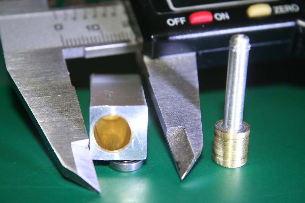
so i took your advice and now it has brass on brass. its nice and smooth and doesn't seem to leak too much. heres a pic, but before anyone says anything, the piston isn't done yet. the epoxy is still hardening to hold the brass on the aluminum piston. i also used a cheap macro lens to take the pic, so thats why the piston looks bent. im also working on a new Crankcase so that i can make it a 2 cylinder "boxer"...
and here is a pic of the completed single cylinder engine..
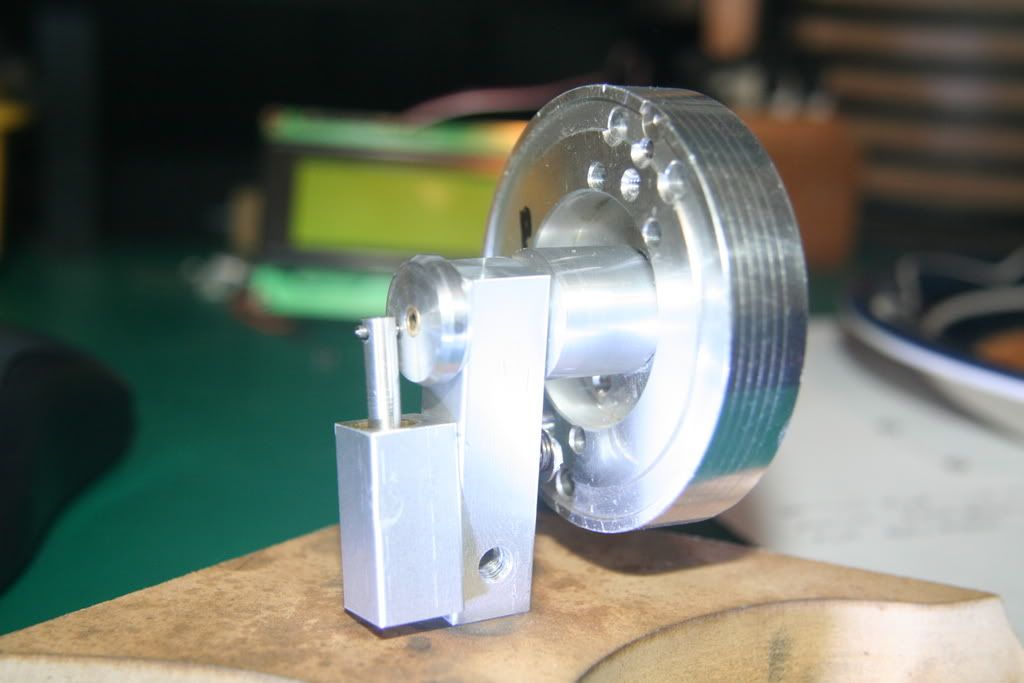
the intake hole at the bottom is threaded and then i have a hose from my compressor that threads into it...
i will put plans up after i get it all straightened out, but it was made completely on my 10x18 lathe with a 3-jaw chuck. the holes in the cylinders are offset because it was square stock in a 3-jaw, and all the side holes were done by clamping the aluminum in the toolpost and putting the drillbit into the chuck.
Betcha ya cant guess what the flywheel is from!!!!
-
06-06-2007, 02:07 PM #7
Gold Member
- Join Date
- Jul 2005
- Posts
- 12177
Betcha ya cant guess what the flywheel is from!!!!
It looks a bit like the scan head from a VHS machine.An open mind is a virtue...so long as all the common sense has not leaked out.
-
06-06-2007, 02:16 PM #8
Registered
- Join Date
- Dec 2006
- Posts
- 45
yup... its cheap and easy to get!!!
-
06-06-2007, 03:47 PM #9
Banned
- Join Date
- May 2006
- Posts
- 138
What is your bearing material and crankshaft made from? Brass or bronze would be good for bearing with steel crank.
Why did you go to the trouble of making liners for cylinder and piston? it would have been far easier to just machine from solid brass!
-
06-06-2007, 06:29 PM #10
Registered
- Join Date
- Dec 2006
- Posts
- 45
i wrote a big long reply, and it disappeared so here it is again. Originally Posted by nick.gilling
the crankshaft is a brass tube (i know its not the best, but it works), and it runs on ball bearings.
i made the liners because i dont like machining brass, and the only brass stock i had was 1"dia. i also made it all out of aluminum originally, so all i had to do was turn down the old piston and drill out the cylinder. and as a bonus, the piston and cylinder (the moving parts) are lighter because there aluminum.
even if its not the best way to do it, it still works, its made entirely out of scraps, and im having fun doing it.
-
06-06-2007, 06:37 PM #11
Banned
- Join Date
- May 2006
- Posts
- 138
Oh in that case it was a good idea to avoid making new components. I am sure you will find it will run much better now.
The flywheel looks fine. If it still doesn't run freely and on a low pressure, the only area's I can see as a problem are the port faces, again you have aluminium to aluminium which isn't ideal. You could mill out a relief in the bearing pedestal as it isn't all needed, that will reduce friction.
What are the crank pin and big end made from? I usually use silver steel and brass for those, but it's that thin it shouldn't cause undue friction anyway.
The only other problem you get with these is how accurately the ports are machined, is there a way of telling if they line up when the crank is at 90 deg after TDC and 270 deg after TDC?
-
06-06-2007, 10:36 PM #12
Registered
- Join Date
- Dec 2006
- Posts
- 45
Originally Posted by nick.gilling
ok, so i guess there really isnt a magic way of making it run off of low presure, other than getting rid of as much friction as possible and making parts fit perfectly.
my ports probably arent perfect, i just drilled them where it looked good. the next "crankcase" is going to be different and actaully designed first instead of just sticking parts together....
-
06-07-2007, 06:35 PM #13
Banned
- Join Date
- May 2006
- Posts
- 138
Yeah that's the way to do it, either have a system where you can drill right through the cylinder and plug the outside hole (then they'll be spot on) or calculate where they should go and make it as accurately as possible.
To get one to run on low pressure the bore sizes we're talking about are too small. Go for a bore and stroke of maybe 5/8". That way you get a bit more torque on the crankshaft and more force on the piston for a given pressure. A flywheel like you have is also important with the mass concentrated around the outside to give it a high moment of inertia and keep the thing turning over until the next power stroke.

Similar Threads
-
CNC mill questions - thrust bearings, leadscrew mounting, general questions
By tonofsteel in forum DIY CNC Router Table MachinesReplies: 8Last Post: 02-03-2012, 10:42 PM -
Some CAD/CAM questions... new to CNC
By Cool625 in forum Uncategorised CAM DiscussionReplies: 25Last Post: 02-06-2006, 03:19 PM -
VFD questions
By chrispy in forum CNC Machine Related ElectronicsReplies: 2Last Post: 08-30-2005, 04:03 AM
