


Thanks Bob, Yes a gang tooled slide would be nice. I'll have to get pretty motivated again one day before I put much work into this machine again. For now it is a just a lot of fun to use as is.
Will, the turnbuckle link just stops the belt from tugging/pulling on the headstock. I should have had it there from the get-go. Without it in place, vibrations/ resonances would be transferred into the surface finish, mainly at higher spindle speeds while feeding slowly. It made a pretty big difference.
Steve
Thread: A benchtop cnc lathe build
Results 241 to 260 of 296
-
07-09-2008, 11:45 PM #241
 Registered
- Join Date
- Mar 2006
- Posts
- 357

-
07-13-2008, 09:50 PM #242
Registered
- Join Date
- Mar 2006
- Posts
- 357
Possible new lathe build ? version 2
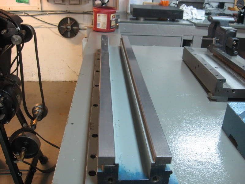
I scored an unreal deal and brought home this 36" Gilman slide. It appears to have never been used and just stored away.
Box ways, hardened and ground, .0005" /3ft accuracy.
Super smooth motion. It weighs in at 200lbs. The carriage would need to be shortened.
This would make a fantastic z axis and base for a nice cnc bench lathe.
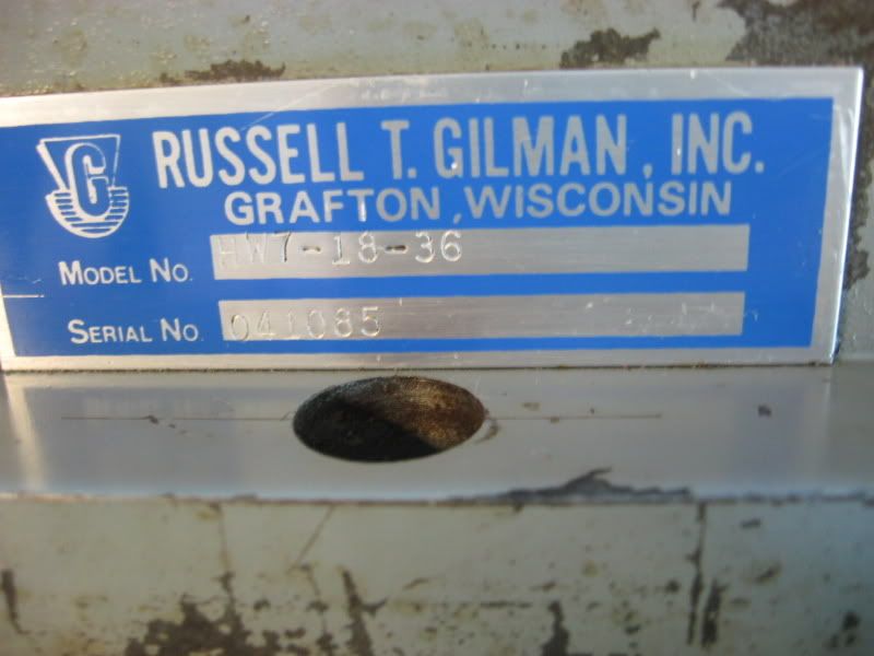
Gilman was acquired by SKF some years back, Product specs- http://www.skfpt.com/hrd-way-features.html


Steve
-
07-14-2008, 12:50 AM #243
Registered
- Join Date
- Sep 2006
- Posts
- 607
Make a mill! Use it as the collumn!
-
07-14-2008, 03:03 AM #244
Member
- Join Date
- Sep 2006
- Posts
- 6463
Hi Steve, quite an aquisition, and in your shoes I'd also grab it.
As it stands it's quite useless for anything resembling a CNC machine, just too much weight.
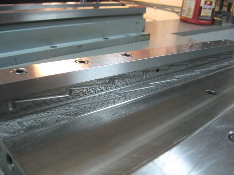
The first thing I'd do was to remove the carriage and the two slide ways as they are, this leaves you with an accurate base with machined mounts for the linear rails.
Next the carriage would have to be cut in half (or shorter) to build the headstock on.
Then the two rails would have to be cut short the same as the head mounting part to accept the now headstock base.
Although this seems like a bit of butchery it would then would be a very quick build CNC lathe similar to your previous model.
In it's present state the slides are just too massive to even contemplate using as a lathe configuration, even as a conventional lathe, due to the carriage slideways spanning the total width of the two slides, whereas the normal lathe practice, for absolute accuracy, is to have the front slideway only as the X axis guiding factor, and the rear slideway as the carriage rear slide support.
Anyway, the slide design is obsolete in favour of the raised Vees used in all modern centre lathes, but as you're contemplating using it as a super model CNC lathe this would not matter as the linear rails are so much better.
The first firm I worked for in OZ, when I arrived here in 1981, made slides like these for linear transfer machines having 21 stations making parts for the car industry.
This particular slide way as it was originally designed, requires a boxed in base to mount it on, or else the weight of the carriage and the slide itself will bow in the middle under use.
As you won't be mounting a huge machining head on the carriage, which is what it was intended for, you should not have a problem just mounting it on the bench as your previous CNC project was.
In the new design I'd mount the motor directly on the back of the headstock and use toothed belts for the drive.
More capacity, more scope, more horse power, probably will keep you busy for quite a while yet, don't you ever sleep? LOL.
Ian.
-
07-14-2008, 03:38 PM #245
Registered
- Join Date
- Mar 2006
- Posts
- 357
Ian,
Thanks for your input! I am not quite in agreement on some things though.
There are many cnc lathes being built with box ways. Do a google. And they all claim superior damping and heavier cutting ability. Such as this one-

The carriage is 18" long as it sits and weighs 38lbs. I would cut it down to size which would reduce the weight. Since the Mill head on my x3 weighs roughly 100lbs and is on a much cruder built dovetail slide and can easily rapid at 75ipm with ballscrew , I do not think there is any issue at all getting this carriage to travel at some pretty good speeds. I can easily rapid my dovetailed mill table at 100ipm and it is much much heavier than this carriage would be. Using just some regular oil this slide is easy to move with 2 fingers.
As far as accuracy, Well Gilman slides are high quality. They claim .0005" in both horizontal and vertical plane over 3 feet. That is better than the slides on any machine I own.
Lot's of thinking and planning needs to be done before /if I start this project!!
-
07-15-2008, 02:46 AM #246
Member
- Join Date
- Sep 2006
- Posts
- 6463
Hi Steve, true, at least you have a good starting point whichever way you go.
That's an awesome bit of Meehanite in post #245.
Ian.
-
07-15-2008, 02:54 PM #247
Registered
- Join Date
- Mar 2006
- Posts
- 357
Well, I had a little brainstorm last night while staring at that slide. I have 3 lathes right now. I only have 1 mill but it's decked out pretty good with a 4th axis. So making another cnc lathe is sort of a waste of my time. But once in a while a job comes up when line boring is the best procedure. Such as when I line bored my SB9A headstock to fit bronze sleeves- This is the thread where I described my process in detail-
http://bbs.homeshopmachinist.net/showthread.php?t=26578
Now it sure would be nice to have a specialized setup just for line boring.
So what I'm thinking of making with this slide is a sort of Horizontal boring machine. For line boring mainly. This bed is dog gone accurate and If I split the carriage into 3 units It might just work. First carriage unit would mount a small milling head on a vertical slide. Second unit would be a t-slot table with an x-axis slide. 3rd unit would be for an out board bearing that also would be adjustable vertically.
This would be a manual machine but I'll probably put a stepper on it just for power feed.
Any thoughts?
Steve
-
07-15-2008, 03:11 PM #248
Gold Member
- Join Date
- May 2005
- Posts
- 2502
Set the slide up as a generic axis with a ballscrew and stepper. Fixture the moving plate with a grid of threaded holes and dowel holes alternating for precision location.
Now you have a "modular axis" that you can use as you see fit to create Line Boring rig are anything else that suits. If you decide to turn it into a machine down the line, you've done nothing to it to interfere with that function and indeed done part of the work.
Cheers,
BW
-
07-15-2008, 08:41 PM #249
Registered
- Join Date
- Apr 2007
- Posts
- 521
Steve,
How much Z and X travel do you have on the lathe?
-
07-16-2008, 04:36 AM #250
Member
- Join Date
- Sep 2006
- Posts
- 6463
Hi Steve, a horizontal borer, wow, in at the deep end.
I worked a Kearns Horizontal borer for 20 years on and off from '58 to '78, nice machines and so user friendly.
The vertical column and head will get your design team working overtime, but nevertheless, an interesting project.
Ian.
-
07-16-2008, 07:26 PM #251
Registered
- Join Date
- Mar 2006
- Posts
- 357

ah hell, I think it'll just cover it up and store it for now.
Will, around 10" or so of Z and 4.5" of X.
-
07-17-2008, 11:59 AM #252
Member
- Join Date
- Sep 2006
- Posts
- 6463
Hi Steve, just looked at your link in post #247 and would like to point out that this method while achieving two round bores is not considered line boring as such, and no claim can be made for accuracy, although to some degree, while not apparent, innaccuracy is present.
Line boring, and it's inherently accurate results, are achieved by having the boring bar rotating with a single tool in a fixed position relative to the X axis, and moving the job along it.
On the SB lathe this would have best been accomplished by sliding the headstock along the bed with the saddle, if the base of the headstock also had the vee bearing grooves as the saddle to bed arrangement, and having the boring bar between the centre and the rotating mechanism to the left of it.
I line bored many bearing set-ups on a horizontal borer and this is the only acceptable way it's done.
You can line bore proper, in the lathe, by having the boring bar between centres and the job on the saddle, traversing the saddle along the boring bar as required, as long as you can allign the job to the datum faces.
You cannot have the tool in a different position along the bar if for instance the bores are far apart and the carriage doesn't have enough travel, otherwise you will produce two holes, although round, will not be in line.
The boring bar in an exageration can be off centre to the X axis of the borer/lathe etc as long as the job traverses past the single tool that is rotating in the bar which is also fixed.
These are fundamental facts and any deviation is not considered accurate as would be had in line boring proper.
Boring a hole in a job in a vertical mill with a boring head will achieve the same results as line boring provided the quill is alligned to the job datum faces in two planes
The only problem with boring with a boring head type set-up is the deflection in the boring bar that can take place, but this will only likely occur if the boring bar diam to length ratio exceeds 4D, and then only on the initial roughing cuts, which will eventually decrease but not completely dissapear as the finishing cuts are applied.
To sum up, the job moves, the tool rotates but stays put.
In all cases the datum faces of the job will have to be alligned to the horizontal axis of the traversing slides in two planes.
As a matter of interest I bored the headstock bearings in my lathe, (only .002" to clean up and verify the truth of the existing arrangement), by having a rotating boring bar in the tool post and using the saddle to move the bar through the two bearings.
The bar being 2 inches diam and a foot long with the end turned down to bore the end bearing which was a smaller diam.
I reckon your new slide would make a great borer, just takes a fair bit of work to make it, but it's one of the most accurate machines you can get, that's why horizontal borers (the person) were always paid extra for their skill aquired over years.
There's no such thing as a bad horizontal borer (the person), if you can't make it you don't get the job.
Ian.
-
07-17-2008, 02:12 PM #253
Registered
- Join Date
- Mar 2006
- Posts
- 357
Ian,
A SB9 uses the inner ways to locate the headstock.
I suppose you are technically correct about the term "line boring" That I used for my SB9A procedure. It was IMHO the best method to use with the equipment at my disposal.
You can't argue about the results of the operation though!!!
The 2 bearings are dead in line with one another and inline with the lathe bedways.
Study how I went about it.The makeshift powered boring head was mounted to the carriage. The carriage was moved to the far left of the bed where it was unworn and I verfied this. The headstock was moved to the far left and mounted firmly.
For the first operation of cutting the right hand journal, a close fitting sleeve was made to fit the headstock rear journal to support the outboard end of the boring bar.The headstock pinch bolt was tightened and shimmed as it would be in normal operation on each side. Then the first journal(right side) was cut by moving the carriage along the ways a total of around 2" travel. Once that journal was finished a new sleeve was made to fit the now finished right side journal, the toolbit on the boring bar was moved to the rear position to cut the left side journal and a steady rest installed for outboard support of the boring bar. Then the carriage traversed once again along the exact same 2" of the bedways that was used to cut the front journal.
The spindle turns wonderfully smooth with only .0005" TOTAL clearance on each bearing.
Of course I do not run it that tight and keep it around .00075".
My SB9A even with it's worn bed will turn a 6" length 2" OD bar with only .0004" taper. I'm pretty happy with that. This machine was destined to be scrapped before I took possession!
The spindle will spin at 1500rpm without issue. Spindle runout is well under .0002".
My plans for the Gilman slide however, were in line with your above descriptions.
That is the work would will be moved and the bar stationary.
I might still do it. The slide is to nice to not do anything with it.
Steve
-
07-18-2008, 04:47 AM #254
Member
- Join Date
- Sep 2006
- Posts
- 6463
Hi Steve, yep I know what you mean, all roads lead to Rome etc.
If you had all the machinery you could possibly need then that's a different matter.
I see the SB has a bed like the old Colchester Bantam, (circa 1930) I have, with the saddle also carried on two raised Vees, but the Colchester having a gap bed and the headstock a part of the bed casting all in one.
When I got the Colchester it was much the worse for wear, in that the bed had .013" of wear from midway to the chuck, making it impossible to adjust without the saddle lifting at the chuck end when running if it was adjusted to be a sliding fit further towards the tailstock.
So I recut the Vees by hand with a hand planer device I made, that slid along the bed using the unworn parts of the bed between the slideways.
I think I showed it before, so I won't bore you with details.
Looking at the size of the Gilman slides you've got makes me think that you could get an old lathe similar to the SB and use that standing vertically as the vertical column for the borer.
Would probably take little time to mount it compared to going in cold and fabicating from new.
I think just maybe a milling machine vertical column and head would do if the column was detachable from the base, and of a square design with dovetails and with a head that could be swung round 90 degrees to give the horizontal axis.
That would be about 75% of the work in one package.
Ian.
-
07-18-2008, 02:06 PM #255
Registered
- Join Date
- Mar 2006
- Posts
- 357
Ian, Yes my bed suffers from a similar wear ridge that just gets progressively deeper near the chuck. If I snug the carriage lock near the chuck I can only traverse about midway to the tailstock before it will lockup.
I do remember seeing your planer. Very interesting. I'm not sure I have the skills to try something like that on this lathe. I do need to rebore the tailstock quill bore though. It has already been rebored and fitted with a bronze sleeve by somebody before me who did not do a good job and is out of alignment with the ways.
Well I do have my old mini mill dovetail z axis column. A spare mini mill head, and lots of other spare machine parts that could get me started on this project.
Another member posted a link to this old machine. What do you think of the vertical slide arrangement? Is that the way I would want to go about it?
-
07-19-2008, 04:39 AM #256
Member
- Join Date
- Sep 2006
- Posts
- 6463
Hi Steve, I really like that old borer you showed.
Pretty basic, but definately a horizontal borer proper.
The planer thingy I made was just an afternoons "gotta do somthing to fix it" solution to a situation that just wouldn't go away.
I utilised the unworn metal between the slides and on the edges as unworn datum faces that were as accurate as the machining when it was made.
If you carefully examine your lathe you will find a number of unworn machined surfaces that can be used as tracks to carry something like the slideway planer I made, nothing exotic, I didn't even have a mill to make the bits and pieces then (1982).
If you ever want to go down that track of bed restoring, and I can assure you it's the easiest thing in the world if you have patience, I can email you direct or post on the forum a heap of photos of the device, and as long as you're prepared to do a bit of real scraping (not the grinder bit LOL) you'll end up with a bed that is so true you can bore a hole that is parallel and with no trace of taper, which takes some doing even on a new Chinese import.
With the borer project the biggest task you will face is to attach the vertical column to the machine base, as in the real thing the base swells out at the headstock end to make a flat mounting face that the vertical column casting can be accurately and firmly bolted down to.
An alternative to this is to make a right angle box affair that can be bolted to the back of the base you now have, and attach the vertical column to it depending on how the column is made.
If you can get a vertical mill column that has a seperate attachment point at it's base, then you're almost there.
Otherwise you'll have to make a base casting or fabrication interface etc etc to mount it.
Either way you will need also to have the milling head, that will form the new borer headstock, in the horizontal plane, so the mill derived head will have to be able to rotate to achieve this, something like a Bridgeport head that can turn 360 deg.
If you look at a Bridgeport type head in the horizontal plane you will see the controls are exactly in the right orientation for your project, that is the quill lever will be at the top with the spindle bore pointing to your right side or to the tailstock end, also it's self powered.
In the photo you posted you will notice the drive mechanism is by off the head drive belts which are a problem with a fixed motor and and a moving head.
Having the controls on top may be awkward to use so the fine feed wheel on front would be the most used control, but for drilling etc the quill feed lever now on top shouldn't be a problem to use.
You could also make a right angle drive to bring the quill rapid movement to the front.
On the Kearns borer I worked on we had a set of light verniers that read the rules that were on all slides.
You would probably fit a readout on all slides, especially the tailstock, which MUST be at the same height as the headstock for line boring.
Your problem here with readouts is they are of no fixed starting point, unlike like a conventional fixed vernier scale that is attached to the headstock and tailstock being both zeroed at their starting point.
I personally like conventional vernier scales with magnifiers to read the scales, they're inherently accurate, but readouts are so much more user friendly if a bit costly.
This would be an awesome machine that would more than rival a conventional mill for most projects, but then so is a vertical mill, both have merits.
Ian.
-
07-19-2008, 07:29 AM #257
Registered
- Join Date
- Mar 2005
- Posts
- 1673
 Originally Posted by handlewanker


-
07-19-2008, 04:57 PM #258
Registered
- Join Date
- Mar 2006
- Posts
- 357
Ian,
Yes, I would very much like to see everything you have on the lathe bed planer you made! I think many of us would like this information so please feel free to post the photos and information in this thread if you like.
Well, The mill head I have is just a stationary spindle, like the lathe head. For this project, if I do decide to give it a shot, Do you think a milling head without a moving quill would be satisfactory? I realize It would lose some functionality.
Lol, Yes, I'll be doing some real hand scraping this time.
Steve
-
07-19-2008, 11:06 PM #259
Registered
- Join Date
- Mar 2006
- Posts
- 357
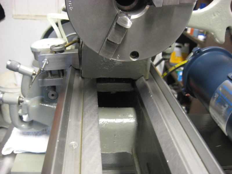
It's official. I have started the horizontal boring mill project. I'm uploading pics of initial work done today and will start a new thread as this new machine buildup has nothing to do with the cnc lathe I built.
Steve
-
07-25-2008, 04:22 AM #260
Member
- Join Date
- Sep 2006
- Posts
- 6463
Wow Steve, you little ripper, (OZ for great guy, blessed with unimaginable advantages that mere mortals are without), is there no stopping for breath...LOL.
This is going to be one hell of a ride, and as it's a topic close to my heart, I'll be watching with bated breath.
When you get to the vertical column design bit, make sure you design for rigidity, as there's no room for compromise here.
A very usefull feature is the quill in the head, (like a vertical mill head) as opposed to a fixed spindle in a lathe, and makes drilling so much easier with the more sensitive feel, but I've worked on some old borers that didn't have the quill, so it's not really an El Biggo disadvantage if you decide to do without.
Another feature you might want to consider is the built in facing slide in the head that is so very usefull when boring large holes and facing etc (what else..LOL)
This resembles a large boring/facing head, as used on mills, and is like a 4 jaw chuck without the jaws, and is designed to move the facing slide as the spindle is rotating.
With this feature the quill is pulled back into the spindle proper, so that it doesn't interfere with the working of the facing slide.
So, you have a large spindle diam with a bore that has bonze bearings to allow the quill to slide in and out, no need, as in a lathe, for material to pass through the spindle.
In addition the real thing has a counterbalanced head mechanism that exerts positive up pressure to the head so that you are always trying to push the head down against pressure, so avoiding backlash in the screw.
This is accomplished with a counterweight that hangs down behind the column and is carried on two pulleys on top of the column.
One of the most interesting design features of the Kearns (among others) I worked on was the actual work table, that resembled the crosslide of a lathe, but with another Tee slotted table on top that rotated, and was located with a long key to the side so that you could mount a job on it, work on one side, and then rotate the job 180 deg to work on the other side, and be absolutely square to the previous side, well, as good as, depending on the state of the machine.
I'll post the photos of the hand planer device, and as it's mostly self explanatory, won't go into copious details as to how it works, but if needed will.
I see on your SB lathe that there are screws in the middle of one of the between Vee flats that I used for a guide surface.
I didn't have this problem, and so just used two bearings per side for guide rollers on the top surface.
The SB lathe you have has one distinct advantage over the gap bed lathe I have in the recutting of the bed, and that is you don't have a gap in the bed, so the planer device can cut the bed in one continuous cut without the need to end for end the tool as the device runs out of slide way, if you know what I mean.
I would leave the slideway surfaces under the headstock as a reference for allignment and also mainly to facilitate the cutting method which entails cutting from the tailstock end towards the chuck end terminating at the point that the headstock attaches to the bed.
This will leave a step in the slide surface, but this surface is only used for the headstock mount, that is unless the saddle slides go past on either side of the headstock at the end of their travel, in which case only these two Vees need to be cut fully to the end, which means the tool has to be reset to get the far end under the headstock, but leaving the headstock Vee and flat intact.
If you get to making and using this device it might be better to go to three sets of bearings along this slideway, so that you don't get a bumpity bump when the bearing rolls over the screw cavity.
Also, it pays to check the width of the slide way, along it's length, to ensure that it is parallel, at least to a thou or two.
The top surface can only be assumed to be as flat as when the machine was originally made, (fingers crossed), unless you have a large surface plate that can be used to clock the length of the two flats, but failing that it is just a matter of running the device along the bed ways and feeling the contact on the rollers with a .02mm (.001") feeler gauge, which over the length of the bed is "as good as".
When the device is running smoothly you can then mount a dial indicator and check the wear on each slide face.
Only unworn flat surfaces must be used for reference, not any used slideways etc, and you'll be totally relying on these surfaces for the final outcome.
Apart from that, it took me just seven nights to remove .013", at about 3 or 4 hours per night, to "remachine" all three Vees, and all flat slide ways, top and bottom, a total of 9 surfaces in all, prior to scraping the saddle in.
Recutting the bottom flats was an interesting scenario, as during use the device must be held down whilst pushing forward, and on the bottom faces there was a tendency to want to lock up, but by then I was getting a bit blase and tended to "go for it" to get the job finished.
Patience is a virtue and pays off here, so a depth of cut of not more than .001" is the Max.
I used a pointy nosed carbide tipped tool and only had to hone the point to do the last cut on each slide way.
Pardon the surface coating of gunge as it's been under the bench for the last 25 years.
Ian.

 Reply With Quote
Similar Threads
-
80/20 benchtop lathe build
By LeeWay in forum Vertical Mill, Lathe Project LogReplies: 87Last Post: 06-15-2015, 01:35 AM -
DIY benchtop mill build
By mkuivamaki in forum Benchtop MachinesReplies: 36Last Post: 03-19-2014, 08:54 AM -
Looking to build my own benchtop cnc!
By rim basses in forum Benchtop MachinesReplies: 0Last Post: 10-09-2009, 07:20 PM -
Not a Benchtop mill but Dang! You have to see this build.
By praetor in forum Benchtop MachinesReplies: 19Last Post: 05-19-2009, 10:58 AM
