


Ooooooohhhhhh.......a kick in the nuts hey? well now I was just passing the observation that engineers in whatever discipline you care to mention are not born, that is they don't automatically aquire mechanical ability with the first gasp of 02, or in their mother's milk, rather it is a long learning process, and the longer you apply your particular bit of grey matter the more you will learn.
This also means that you can self teach by applying certain observation skills and so become quite clever at what you do even if you do not have formal qualifications, eventually surpassing even someone who practices their skills on a day to day process due to their isolated job nature.
I really like your lathe manufacturing process and progress so far.
By your endeavours I become a bit more knowledgeable and so it profits me to observe you even if you make a mistake, for we only learn by our mistakes and the person that has never made a mistake has yet to be born.
Dear john, if you add shims to one side of an already levelled surface then you've wasted your time levelling it in the first place.
For instance, if you add .25mm (.010") to the bottom of the front base to tilt the centre line axis upwards, then you are effectively creating a hollow under the middle and potentially causing a wedge shaped gap under the headstock which will only be sitting on the very back edge of the shim and back edge of the end anyway. Daft I call it.
As WJH said the lining up CAN be achieved at the machining stage, but even that is nonsense, no apology for my remarks, we're not here to enjoy ourselves, so pay attention and leave your nuts alone.
All you need to line the headstock up is a test bar in the chuck, running TRUE, (if the chuck won't run true use the 4 jaw and MAKE it run true), and sticking out 150mm (6"), and a good dial indicator on the X axis slide.
With the headstock lightly bolted down to it's mating face, run the dial indicator along the top of the bar, making sure the side is true as well or you'll get a false reading.
Whatever your desire for accuracy, you can now rescrape the top of the mounting faces untill the clock indicates zero both ends of the bar.
The headstock can now be tightened down progressively observing any deflection in the dial indicator and making adjustments until the headstock can be tightened fully and there is no deflection worth worrying about.
The test bar is an item that should be ideally hardened and ground with centres in each end, but as this is probably beyond the scope of most people, and even a lot of work places I have had the dubious honour to grace from time to time, when all else fails, you can get away with a piece of 25mm (1") diam silver steel, about 200mm (8") long, and test it for truth etc etc ad nauseum.
I will add a note here that without a test bar you will NOT be able to test the accuracy of the 3 jaw or 4 jaw chuck or the allignment of the headstock to the bed, or the allignment of the tailstock centre to the headstock centre.
If you think you can, then I take my hat off to you, 'cos you're a one off! Never seen it done properly, and wouldn't wast my time on people who try to swim against the stream.
I suppose someone will be quick to say that all you need is a piece of steel in the chuck, 30mm (1-1/4") diam, sticking out about 150mm (6"), and then take a cut along it and test the diam at each end.
Strewth, but you're a hard lot to convince.
Every time you want to test the allignment the bit of steel you've been cutting into gets smaller and smaller, the rule of 4 X diam for stick out applies here.
For what it's worth, the setting up of the headstock must be completed before going on to other peripherals because everything hinges about the ability to present the job to the various slides, otherwise one will just cancel out the other.
Ian, the unrepentent.
Thread: A benchtop cnc lathe build
Results 81 to 100 of 296
-
09-14-2007, 01:47 PM #81
 Member
- Join Date
- Sep 2006
- Posts
- 6463
-
09-14-2007, 02:06 PM #82
Registered
- Join Date
- Mar 2006
- Posts
- 357

Well you know, sometimes things can be taken the wrong way in these forums, as there is no face and voice to go with the words to set a tone and attitude.
So, Ian if that was a compliment of sorts then I appreciate it.
John, Well see I don't consider a shim a Band-Aid in this area. I consider it the final adjustment. It would be nice to get it dead perfect but a lathe headstock has to be really "on". I know many lathes have shims placed under the headstock to tweak in the adjustment. I have tried to come up with a good tilt adjustment but can't think of anything simple enough to add to this project. I will have adjusters for side to side alignment.
I'm not an engineer and have no formal training in anything to do with this hobby. I was into cars for over 25 years of my life. Not much that I can't do on a car. I did a lot of welding and fabrication over the years and working with metal was always enjoyable for me.
So when I found my way into machining it was all new to me. So much to learn. A whole New World of knowledge. I enjoyed the precision of metal machining. I have only been into this about 4 years although my first experiences with lathes was way back in high school shop when the schools did offered such a class.
So the lathe I am building represents my current skill and knowledge level which is not much. But everyday I spend a lot of time reading and trying to learn on my own as I have no mentor.
I am not even close to where I would like to be one day. I look at what the real skilled machinists do and I am totally amazed!
So I can take any criticism or use any good advice. I may not follow it but I have a very open mind.
I have hopes my lathe will work well. In 20 years I hope to look back on it and say, yes I had a fun time making that machine.
So I painted the bed after uglifing it horridly in the bluing/scraping process.
A nice heavy hammered finish.
This weekend I have some time to work on it again.
Steve
-
09-14-2007, 02:11 PM #83
Registered
- Join Date
- Mar 2006
- Posts
- 357

ok ok ok, No shim! I'll do it right and rescrape the head stock surface as needed for tilt. I am pretty good at the test bar alignment method of the headstock so I should not have any problems. I did not think of how the shim would totally create a gap under the head stock.
Steve
-
09-14-2007, 02:15 PM #84
Registered
- Join Date
- Mar 2005
- Posts
- 1673

-
09-14-2007, 05:37 PM #85
Member
- Join Date
- Sep 2006
- Posts
- 6463
'lo John, getting a bit testy in your old age?
Been reading the posts as you suggested I should have.
I didn't see your cry for help previously, otherwise I'd have thrown an olive branch, only Koalas have the capability of digesting gum leaves.
If you want a few pointers on getting into the scratching game I'd be too glad to give you my knowledge for what it's worth.
We are not experts by any stretch of the imagination, but we do pick up a few tricks and achieve results as we go along, and that is what counts.
So if I have inadvertently ruffled your feathers old chap, have a heart, I'm an old geezer too, but I don't recall you ever having rubbed me the wrong way in another thread, maybe oldtimers is setting in, so I'm not trying to belittle you.
As for now, catch up on your beauty sleep and I'll try to be a bit more informative and a bit less critical of other people's methods, even if I heartily disagree with them.
Doesn't mean I'll not disagree, but perhaps just suggest an alternative way.
WJH, the headstock allignment must be done from the beginning, that is with a test bar in the chuck and running true in the bearings, and with the headstock on the surface plate.
Check the run on the top of the bar and attack the bottom face to correct it, either by machining or any hand method that comes to mind.
Then correct the mounting face on the lathe with relation to the slideways. On a conventional lathe with the slideways as part of the bed casting, the headstock mounting would have been machined at the same time as the slideways and so would have been true to them, which would have made touching them unnecessary.
You can then mate the headstock to the base and do the final checking with it bolted down.
I would not use shims to correct any up or down errors on the spindle allignment, but would scrape the whole area of the mounting face on the bed to a known flat surface and just take off the amount where needed to bring the h'stock up or down.
What you are trying to achieve is to have a flat surface that is truly horizontal and alligned with the slides.
The best you would want to get is probably a run of .02mm (.001") over a 150mm (6") length on the bed.
Under the methods of construction to expect better than this would leave you tearing your hair out in frustration as you chased thous that in the end would not affect the machineability or the accuracy of the machined components anyway.
I'll qualify this statement, the components you would be machining would never be sticking out of the chuck or collet by more than 150mm (6") without tailstock support, so if you attained the accurcy of .001" over 6" then you are home and dry.
One of the big problems with composite component construction is that there are so many things that can go out of allignment, and the end result is a compromise to allow the show to get on the road.
At this stage we won't even consider the effects of the co-efficient of linear expansion of alluminium, as the temperature of the work place would probably be within the comfort zone of the worker anyway.
In the end we will strive for perfection and accept what we achieve.
Ian.
-
09-14-2007, 09:52 PM #86
Registered
- Join Date
- Mar 2006
- Posts
- 357
Ian, thanks for the detailed alignment tips. I honestly did not think to check the spindle and test bar first on the surface plate. This makes a lot of sense.
.001" in 6" is not going to be a problem.
I have learned quite a bit from both you and John!

Now back to that silly little project of mine.:idea:
Steve
-
09-14-2007, 10:17 PM #87
Registered
- Join Date
- Mar 2005
- Posts
- 1673
I’m only 42 btw. Right where’s these new pictures then get to work man and less of the silly (wedge) Originally Posted by S_J_H

John
-
09-15-2007, 01:23 AM #88
Registered
- Join Date
- Mar 2006
- Posts
- 357
From your handle I thought you were an old man, not a youngster!I’m only 42 btw
I'm 46
Steve
-
09-15-2007, 10:25 AM #89
Registered
- Join Date
- Mar 2005
- Posts
- 1673
Long story, lets just say when I joined I felt very old. Originally Posted by S_J_H
John
-
09-15-2007, 10:42 AM #90
Member
- Join Date
- Sep 2006
- Posts
- 6463
Yeah, I thought he was a bit old too.
Hi SJ, as a matter of fact I would consider your project in the highest calibre.
There are so many things that can go out of wack, and it's a real pain to have to go back and change the design or something.
I would venture to say that although the design is unconventional, so was the Concorde, it will still do what you want it to as long as you just keep applying your logic, and reason each problem out.
This is how the best engineers work at it.
Even with a full set of working drawings, there's always something that gets overlooked and that's the fly in the ointment big time.
I defy anyone to make a design for a conventional centre lathe and not end up with some hiccup or unforseen hitch along the way, and that's when you consider that the lathe has been around for at least a century in it's present state of development before CNC.
Most of us are working with the aim to produce one only, whereas the lathe manufacturers have made prototypes and field tested them to get the production right, and what you finally buy has had it's forebears doing many trips back to base dragging bits that fell off, I think production race cars are like that.
That reminds me of the Great Panjandrum, dreamed up by some members of the officer class in the 2nd world war, to storm ahead of the troops when landing on the beaches to set off mines, well nigh annihilated the officer observer corps.
I can't wait to see the wheels go round.
Ian.
-
09-17-2007, 04:48 AM #91
Registered
- Join Date
- Mar 2006
- Posts
- 357
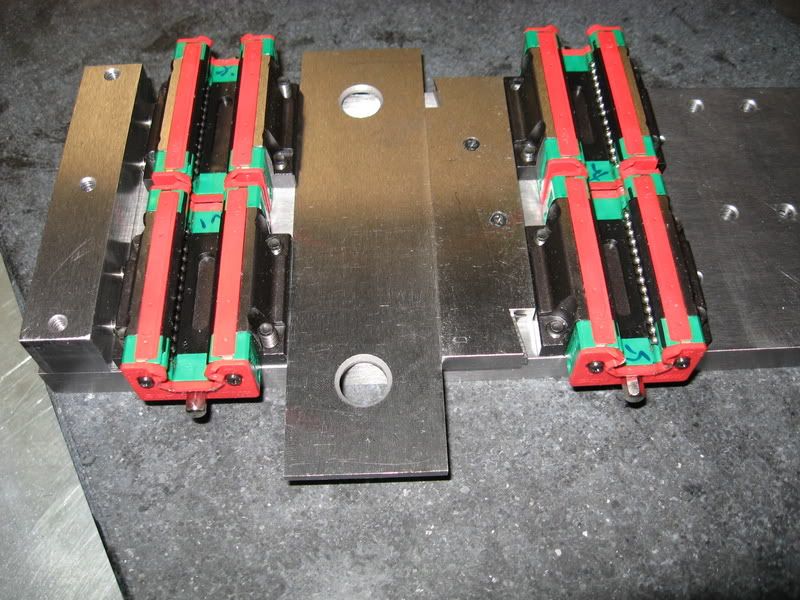
A few new pics. The rails are mounted and now have formed the lathe bed "ways". I have to disagree with Ian's thought's that the headstock should be mounted first. It is a very long time consuming job to mount the rails and have them run truly straight. To try and do that at the same time as aligning the headstock would be a monumental task of tail chasing. The slightest torque or twist with these 15mm rails can throw them off .0005". IMHO you need to first establish the bed ways by precisely setting the rails which is quite a task to do it to a very low tolerance.
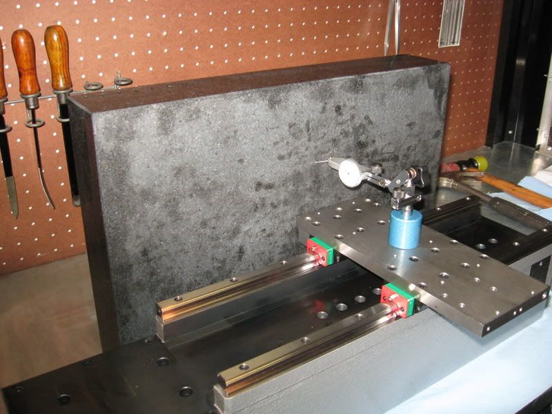
I made a pusher block mounted to the carriage to act on the 2 linear blocks for the master rail. This will also increase rigidity. For the reference surface I tried using parallels and a long straight edge. But I was not satisfied with the method. Instead I setup the surface plate so it could be used as the reference straight edge to set the master rail.
My max variance in carriage travel over 12" is ~.0002" but it's at ~.0001" for the first 10" away from the headstock. Now just how good the machine holds this tolerance will remain to be seen. But surfacing the rail risers made a big difference.
Headstock alignment is roughed in right now. I still need to make push/pull screws. With just tapping to set it I have it set at .0005" out 8" from the chuck. Vertical is out .001" 5" from the chuck rising upwards. That I will leave alone as the effect on cutting is so small it is not of any concern.
I found this concering vertical alingment on a lathe at the practical machinist site-
" A vertical movement of .005" of the cutter bit will have less effect on the turning diameter of the work than you may think. For example, lets say you are turning a piece of stock down to one inch (1.000"). You have the cutter bit set exactly on center with the work and it is cutting exactly at 1.00000" (at least, at the beginning of the cut as it moves towards the headstock). As the carriage assembly moves closer to the headstock, it passes over the worn section of the bed and the tip of the cutter drops .005" below the center line. By applying the Pythagorean Theorem, the diameter will increase to 1.00005". Of course, the error will be greater as the diameter of the work gets smaller because the ratio of the error to the diameter increases. For example, when turning a piece of stock down to .25000", the diameter will increase to .25020". Still, not too shabby."
I'm only at .001" 5" out from the chuck.
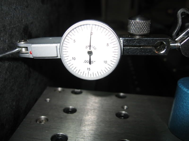
The last pic shows the carriage travel deviance from 0 at the end of the bed.
-
09-17-2007, 01:03 PM #92
Registered
- Join Date
- Mar 2005
- Posts
- 1673
Originally Posted by S_J_H
Originally Posted by handlewanker
John
-
09-17-2007, 01:31 PM #93
Member
- Join Date
- Sep 2006
- Posts
- 6463
Hi SJH, nope, re post #91, I assumed the rails were already set-up and so could be used for a level surface and checking point.
What I meant was the headstock bottom must first be made level and true to the spindle centre line by using a test bar in the chuck and dialing it on the surface plate, after which it can be mounted on the prepared base and checked for allignment to the rails.
You're quite right about the above/below centre differences not making a 'haporth worth of difference, as long as you get the 150mm (6") out good to a thou' the rest will just go along for the ride.
Incidently, and just as a matter of interest, a turret lathe has the centre height very accurately alligned because they use a "knee tool" to produce parallel work on a repetition basis, and this tool cuts along the top of the work from the turret slide, and it is this function that allows work to be held to diam tolerances when the operator is pushing the production, but for your set-up the height allignment is not that critical, unless you are going to have tools in the turret that cut on the top of the bar.
I read back over the posts to get the background again, one of your best decisions was to get the surface plate.
I think if you had opened a thread with the proposal to build this lathe from a design concept without drawings, you would have got a million reasons why it could not be done without a whole heap of expensive gear, but it just goes to show you, if you get the show on the road and work round the design it will eventually fall into place.
Congratulations, can't wait to see the wheels go round.
Ian.
-
09-17-2007, 02:04 PM #94
Registered
- Join Date
- Mar 2006
- Posts
- 357
Ian, sorry I misread your post.
I have to agree, that building a lathe that will be worth a dang is a very complex project. I had no idea how time consuming it would be just to get the rails lined up to the point where I can call them "precise". It took me 2 days of work to get them to this point. I have to wonder how many guys using linear rails actually have them setup nice and straight. It's been said one can not make a machine any better than the machines used to make it. I reasoned because I am using linear rails and not milling/grinding dovetail or sliding ways I could actually make a machine superior to what I have now. I still believe this but it is not a simple matter of buying some rails and bolting them down!
I have done a LOT of reading on lathe designs over at http://www.lathes.co.uk/index.html
I find it fascinating reading! I could not even imagine trying to make a manual lathe with change gears etc.
I have 3 more ball nuts ordered so I can finish the ballscrews and preload dual nuts, belt drive components for the cross slide and a proximity sensor for the spindle on the way.
Steve
-
09-17-2007, 02:47 PM #95
Member
- Join Date
- Sep 2006
- Posts
- 6463
Hi Steve, If you look at centre lathe design using raised Vees you will notice that only one slide way is the guiding way, the other, a flat slide, just carries the end of the carriage and prevents it from twisting around the X axis.
Using linear bearings and having two rigidly alligned bearing surfaces over the total length of the bed makes lining them up very difficult compared to common centre lathe practice.
However there are a number of lathes that have two Vee slides to carry the carriage, and to get the carriage to ride on them equally and evenly for the total length of the bed without binding is a piece of cake, due to the fact that the carriage can be fitted to the bed by scraping the two Vees on the saddle to fit the bed, as long as the bed is true.
This is of course impossible with linear bearing slide ways, as they are a pre assembled package and have to be set down and alligned to each other or binding will occur.
But they do run so very smooth and, if correctly set up, very precise and accurate.
I think that lathe design should be taken in consideration when doing a project like yours, but with the use of linear bearings, ball screws and stepper motors doing the moving, a different approach is needed to get the full benefit of this design method.
There is no way that you could think of that would make milling Vee slides a superior method for a CNC lathe, just too much friction to overcome when the slideways are adjusted to the minimum clearance.
Apart from that, you would have had to have a casting made, if the conventional method of lathe construction were to be followed, which means a large machining set-up, not even an option when you can buy a lathe that will out perform any home built lathe at half the cost.
Your CNC project is an exciting venture, and I wouldn'nt mind betting that you have hundreds of fans "tuning in" to get the latest results.
Ian.
-
09-17-2007, 02:54 PM #96
Registered
- Join Date
- Mar 2005
- Posts
- 1673
And I would be one of them :cheers: Originally Posted by handlewanker
Now less yapping and more building is called for I think
John
-
09-17-2007, 10:29 PM #97
Registered
- Join Date
- Nov 2004
- Posts
- 284
Hi Steve
What is the purpose of the bar & adjustable parallel you have between your Linear Bearings? I see that you have a set of set screws pushing everything together. Thanks for the help and keep up the good work.
Willy
-
09-17-2007, 10:50 PM #98
Registered
- Join Date
- Mar 2006
- Posts
- 357
Willy, the parallels were just temporarily installed to test out the pusher block I made.
Steve
-
09-18-2007, 12:09 AM #99
Registered
- Join Date
- Nov 2004
- Posts
- 284
Hi Steve
What is a pusher block?
Is the item behind the Spindle Housing that is belted to your Spindle an Encoder? What did you use for an Encoder?
I happen to have a 1-1/2 hp, 3 Phase Motor and Hitachi VFD that I was thinking of using for a CNC Lathe build similar to yours. I know it's over kill but I have the stuff and might as well use it. I was thinking of mounting the motor at the rear of the Spindle Housing and drive the Spindle with a couple of belts. I also have a couple sets of Linear Rails that I picked up for another project that never got used and would look good in a Lathe.
What are thoughts on using this Motor/VFD set up with the same Spindle you used?
I have learned so much from reading about your lathe project. Thanks for the help and keep up the good work.
Willy
-
09-18-2007, 12:48 AM #100
Registered
- Join Date
- Aug 2006
- Posts
- 19
Trivia question for Steve
Steve,
Really awesome thread you have here. Been reading it as it goes. You
are getting into scratch build areas that are giving me just the info I need
to aid in building a from-scratch cnc mill design.
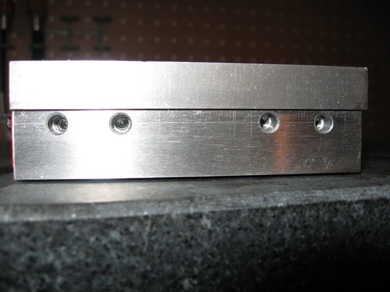
My trivia question is: what size cap screws and length did you use on your
15mm rails to lock them done to your rail risers? This is exactly the size
rails I have to use on my Y-axis. I have been unable to find specs on the
rails I bought on ebay.
Great build.
Jesse (Java77man)

 Reply With Quote
Similar Threads
-
80/20 benchtop lathe build
By LeeWay in forum Vertical Mill, Lathe Project LogReplies: 87Last Post: 06-15-2015, 01:35 AM -
DIY benchtop mill build
By mkuivamaki in forum Benchtop MachinesReplies: 36Last Post: 03-19-2014, 08:54 AM -
Looking to build my own benchtop cnc!
By rim basses in forum Benchtop MachinesReplies: 0Last Post: 10-09-2009, 07:20 PM -
Not a Benchtop mill but Dang! You have to see this build.
By praetor in forum Benchtop MachinesReplies: 19Last Post: 05-19-2009, 10:58 AM
