


Very nice - I especially like that heatsink made from a piece of alu extrusion
It is a shame that ISO30/BT30 holders on straight shanks aren't as common as ER16/ER20 ones - it would save a lot of precision turning, hardening and grinding work.
I suppose though that someone with a lot of skill might be able to graft an ISO40-30 adaptor sleeve onto an existing MT3 or R8 spindle head like the ones on the mini-mill, but it's way beyond my capabilities!
Thread: BT30 Spindle project
Results 41 to 60 of 174
-
10-01-2007, 09:33 PM #41
 Gold Member
- Join Date
- Aug 2006
- Posts
- 1602
-
10-02-2007, 11:16 AM #42
Registered
- Join Date
- Aug 2007
- Posts
- 42
Very nice work H.O!
Those bottom bearings should be good for 6500 rpm without any problems. If you ever make another may I suggest a small change to the way you retain the bearings on the bottom of the spindle? A extension of the diameter that the bearings sit on then add a spacer that has may be 0.015mm - 0.005mm clearance and is ground flat and parrel. This will assist with even pressure on the bearings as they are preloaded. The retaining nut will/may twist slightly when tensioned and cause an uneven pre load, possibly causing the cone to run out and causing it to prematurely wear. You wont want to do up the nut to tight as this will guarantee the above.
I have just noticed your post regarding run out :tired: . How much is there? Perhaps you could grind/machine the OD of the thread and fit the afore mentioned spacer as this could be your problem. The bottom keeper plate also needs to have some amount of clearance on the bottom face to ensure it retains the bearings squarely in/against the housing. If you are concerned about sealing the bottom face perhaps an O ring or silicone. If you have a compressed air supply in your shop you could also add a slight positive air pressure to ensure that nothing will get inside no more than 50kpa.
The top bearing may also be causing trouble with run out. It will be difficult with a top side driven spindle but you could try a few things. The top bearing is just a standard radial bearing (6206) and retained with a interference fit on the top of the spindle you could machine the housing to give it a little clearance (0.1mm) and put in a O ring or 2. 3mm section with a 90duro hardness would be ample. This would support the spindle letting it grow when warm and allow for a little run out in the top bearing. The O rings will hold it and this is established practice in some very expensive CNC milling machines. Top-Side driven spindles really need two sets of preloaded bearings but you should be ok?? as long as you keep the drive under 4hp. An NU206 could be substituted for the 6206 as this would give the spindle a lot more side load ability for the drive but it would need to be retained. Once everything is square it would be ideal as it would allow growth and give you the ability to run a tight drive belt (5M or 8M form).
If this doesn't fix your run out you may need to get all your bearing diameters hard chromed and then fit a tool holder that will act as the centre to allow the diameters (don't forget the bottom shoulder the bearings seat against as well) to all be ground in one set up. You could also get the bottom face of the nut ground whilst mounted on the thread to ensure it is square. If you do that don't forget to make a sacrificial spacer to get the nut into the position it will be holding the bearings.
Please don't take this the wrong way as I can see you have done a great job making this spindle from scratch but I have had a bit to do with troublesome CNC spindles over the years and just want to help.
Cheers
Daza
-
10-02-2007, 11:30 AM #43
Registered
- Join Date
- Aug 2007
- Posts
- 42
I nearly forgot, Make sure you have clearance between the bottom face of your tapers as they are not made to run true off that face. For that style of drive you need a HSK.
Cheers
Daza
-
10-02-2007, 04:26 PM #44
Registered
- Join Date
- Jul 2007
- Posts
- 887
Daza,
First let me thank you for a very informative post it's all very much appreciated!
Here's some mixed answers, comments and questions:
The runout is 0.01-0.02mm (0.0006"). I don't know if it's the shaft itself that isn't as concentric as it "should" or if there's something going on with the bearings. If you read the thread from the beginning you may remember I had an "accident" with the housing and perhaps that also has some impact on the runout. I will make some more measurements to see if I can determine if at least the shaft is concentric.
The spindle turns really smooth though - not freely but smooth. Do you think I would feel it if the nut "tilted" and applied uneven preload or would it feel the same? Do you have any idea how hard I should tighten the nut? What I did was to apply some LOCTITE and then tightened as hard as I could with my hands.
I wish I could know if that spacer would help. I don't have access to good grinding equipment so I would need to farm that job out to the local shop = $$$, something I'm running out of on this project.
That "trick" with the O-rings sounds interesting. I may try to take it apart and remove the upper bearing to see if it has any impact on the runout. The upper bearing was quite hard to get into place though so I will need to press it out.
Is 0.01-0.02mm really that bad? I mean I've seen the spec's on some high end spindles but in reallity, for a hobby machine what do you think?
I have an ordinary radial seal for the front bearings, I just havent mounted it yet. I did think about positive preassure but I didn't want to make it TOO complicated in fear of it never being finished - too many of those projects all ready.... It shouldn't be to hard to incorporate but I guess it would make the contact pressure of the radial seal higher causing even more friction?
There is clearance between the flange and the face of the housing so that won't be a problem, applying even pressure all the way around might be though. I may get a tourqe wrench and tighten the screws exactly the same - can't make it worse, right.
And don't worry, there is clearence between the face of theholder and the face of the spindle. I'm not trying to make a HSK or BIG-PLUS ;-)
I am a bit concerned with the lubrication of the lower bearings. Since the spindle obviously is mounted vertical there may be a chance that gravity pulls the grease out of the bearings. As it is now I have no way of re-applying lubrication in an easy way.
Again, thank you very much for commenting and please continue to if you have the time.
/Henrik.
-
10-03-2007, 06:26 AM #45
Registered
- Join Date
- Feb 2006
- Posts
- 1072
Thank you for the pictures, Henrik. Yes, it would be similar, except mine would be for a small lathe. Originally Posted by H.O

Best regards,
Randy
-
10-03-2007, 01:35 PM #46
Registered
- Join Date
- Aug 2007
- Posts
- 42
Henrik
10 - 20 microns run out is not a lot but will show up with long tooling. Where is that measurement taken from, the tool cone? Tool cones are quite difficult to machine (Even machine tool makers get them wrong) and this may be the cause of your run out if you are measuring it on a tool holder. There are some tricks you can use in the tool cone to improve run out but these are last resort. The housing wont affect your radial run out, the spindle shaft and bearings are the things to be looking at here.
If the bearing faces were clean with no moisture/grease between them, and the shoulder is true to the diameter the bearings are mounted on it must be the nut. You wont feel uneven pre load until the bearings are worn out.
I am not a big fan of chilling when fitting precision bearings as it is to easy to get trapped moisture. Just a small amount will cause corrosion and cause lumps underneath the bearings (I have seen this make a 280mm id bearing on a lathe spindle run oval by 0.006-0.009mm total and all it was was a greasy finger print 6 months prior). Just heat the bearings to about 100 -110c already greased. They will fall on and you should aim for a size (bit late now ) that will be no more than 0.005mm interference on the spindle, The bearings are held with the nut not the diameter. You may need to add a little more tension as I would personally use about 8-10deg of rotation of the nut past the bearings seating for that size/thread pitch. I cant give you any documentation for this as it is just a feel thing.
12-15 newtons on the flange screws will be plenty, in 2 steps. Even pressure is never bad but it wont make a lot of difference as the outers will need a lot more force on them than you will make with 6mm screws. How tight are the bottom bearings in the housing?
I wouldn't bother with a seal on the nose as a slinger will keep crud out. 0.1 -0.15mm clearance between faces 5-6mm wide is plenty. Seals get hot, wear shafts and deposit rubber in bearings. With positive pressure and 6000rpm you dont use contact seals. You will need a slinger if you plan to work close to the job with coolant. Positive pressure is easy to set up all you need is a regulator, air supply and a pressure gauge. In a perfect world you would also use a metered port to prevent over pressure but it is not that critical.
Don't worry about the lube of the bearings as you will need to use it 24/7 for 6 months before I would even be looking to add extra grease. If you have used the recommended SKF grease for these bearings it would be more like 12 months before more would be needed in my opinion.
Make no mistake the O rings WORK in a top axial driven spindle. It sounds dodgy and the first time I saw it I wasn't impressed but after maintaining these mills (10000 RPM spindles) for 12 years the O rings have only caused problems when damaged (3-4 times I can remember) during a spindle installation. Being side loaded it may need a heaver section O ring. In the past I have only done this as a temporary repair on some low speed side loaded spindles (1500rpm) where a bearing housing was damaged but the repair out lasted the bearings every time.
The run out you are chasing is only small and to be honest only you will know what is acceptable for your application. I personally wouldn't worry about it for that type of machine.
Cheers
Daza
-
10-03-2007, 03:24 PM #47
Gold Member
- Join Date
- Jun 2003
- Posts
- 2103
There have been several threads here on the Zone about designing an atc spindle, and there have been a couple about the building an atc spindle. I can say without a doubt that this thread has more useable information than any.
I personally want to thank Henrik for the thread and the willingness to share, and Daza for sharing some of the knowledge he has accumulated over the years. This type thread is what I like most about CNCZone.
Now the question. What is the estimated cost of something like this, assuming one has the machines to make the part but less the grinding? What additional cost would be added to take the spindle speed to 20,000rpm?
MikeNo greater love can a man have than this, that he give his life for a friend.
-
10-03-2007, 05:07 PM #48
Registered
- Join Date
- Jul 2007
- Posts
- 887
Daza,
Oooh, I didn't think about the moisture when "freezing" the shaft. I sure hope that won't come back and bite me in the future. I can't say I verified the cleanliness of the bearingfaces when mounting them on the shaft but I can say that if I would've seen something I would have wiped it off. So I assume it's clean. (I know, I know, assumption is the mother of all f-ups)
Regarding the fit of the outer races to the housing, I heated the housing to around 100°C and after that the bearings slipped in easily "by hand".
I measured the runout by placing the whole spindle in two vee-blocks on a big surface plate. I then measured on the cone/taper of the spindle shaft with a dial test indicator while slowly rotating the spindle in its bearings.
Would you care to elaborate a bit what you mean by a slinger? I can't remember seeing the term before. There's 0.25mm radial clearance between the front flange and shaft. Are you saying that if I reduce that a bit it would suffice as protection for the bearings?? (With positive air pressure inside)
As I said, I may end up taking it apart and if I do I will investigate what you just told me and I will add the possibillity for positive pressure).
Once again, thank you very much for your advice!
/Henrik.
-
10-03-2007, 06:23 PM #49
Registered
- Join Date
- Jul 2007
- Posts
- 887
Mike,
Thank you for the kind words!
As I said in the first post in this thread I did a lot of searching/research on the Zone and on the net and I did found some interesting threads but honestly, very few of them materialized. That is not said to cast shadows on those projects or its "owners" but rather to indicate that it IS complicated to build a spindle like this. In theory it looks and sounds easy but as usual the devil is in the details.
So how much does it cost... I made an estimate when I started and I'm well beyond that now, primarily due the cost of the grinding. To give you a ballpark number I have something like $1500 in it now, ~60% of it being the hardening/grinding....I read a thread here where someone said you could send a BP spindle in and have it reground for $300 or something like that so I'm starting to believe I payed way to much...
Bringing it up to 20000rpm will need different bearings (at least) and those DO cost big bucks. If you don't get lucky and score a suitable pair on EBAY you'd probably have to pay more for a set of those bearings than I did for the whole spindle. Also, with better bearings comes even higher demands on the precision of the housing and shaft. And as icing on the cake - at those speeds you'd probably need balanced tooling too.
Thanks again!
/Henrik.
PS. I just read thru my own post before sending it and I realised it may sound discouraging and what not. Of course it is meant as nothing of that kind.
-
10-04-2007, 01:06 PM #50
Registered
- Join Date
- Aug 2007
- Posts
- 42
Henrik
I wouldn’t be to worried about the moisture as it doesn’t really matter with a tool in spindle setup. The worst thing that could happen would be it could make it cut oversize slightly. It is important to keep everything clean though. The higher the grade of bearings the smaller the contamination required to upset them. A spot of grease on the mating faces will make a difference.
For my money the housing sounds too tight, as with the spindle the diameter is only there to locate the bearings the keeper plate holds/stops them from moving. You should never need to heat a bearing housing for a precision spindle (To fit bearings but it is good practice to dry them out, I use a paint stripper heat gun to get the heat in). If you ever get it into the lathe again perhaps a polish would help.
I always measure run out with the housing secured, this way you can also measure deflection in the bearings as well (If there is any). I still believe that a good proportion of your run out could be caused by the top bearing. Just had a look at the You tube video and I think the spindle cone taper is wrong. Those tool holders should stick in there and be knocked out by the air cylinder. In best practice you should be able to use full power on your tooling without keys and witness no movement tool holder ~ tool cone when clamped. If you blue up the cone it should be tight on the very top and size on the bottom. In practice, this is damm difficult to measure and grind. The nature of grinding the cone always seems to make the taper go the other way. I use a CMM to check ours (0.005 – 0.008mm comes to mind but it should be in a tooling hand book somewhere) but you will get it very close with bearing blue. You have plenty of power with that knock out cylinder (Most CNC’s use a 150mm air cylinder though on a BT30) perhaps you could double up the Bellville washers to get more pull and this should assist with tool location. You could send the spindle back to the grinders and get them to fix the tool cone as it is running out and Im sure they would have promised it would run true.
The idea of a slinger is a rotating disk at 90deg to the axis of the shaft/spindle. When coolant or debris is travelling along the shafts axis, it is diverted away by the spinning disk. Some will have enough surface tension to hold on and travel back across the top, so the idea of the wide face and the narrow gap is to prevent most/all of this from continuing back up and into the bearings. It is like a single stage labyrinth seal. Unless you are doing a lot of close work with flood/hp coolant you wont need to add air pressure to the housing.
I have just read this post and despite what it appears like im not trying to pick your work apart. Don’t be offended it was not my intention. Good luck
Cheers
Daza
-
10-04-2007, 02:12 PM #51
Registered
- Join Date
- Aug 2007
- Posts
- 42
Mike
20000 rpm with a BT30 you don't want much do you. :drowning:
To get those sort of speeds with such large bearings is a challenge. You could get it up to 15000 rpm with a few changes with a greatly reduced load capacity though.
I wont go to deeply into the bearings only to say that there are high speed bearings available that carry the same external dimension and load rating but with a different internal design. You can easily pick them by a greater compliment of balls than standard. They also use smaller diameter balls to aid in a reduced contact area per element thereby reducing friction per ball. Have a look at this for more bearing info http://www.fag.com/content.fag.de/en...n.pdf&y=0&x=0&
A good rule of thumb is less is better the faster you go.
You could start with Henrik's (Sorry Henrik) basic layout, add spacers between the bottom bearings that would be approx 1-1.5 times wider than a single bearing. Then use a needle roller bearing for the top (Smaller size the better) reducing the spindle diameter as much as possible. You could side load drive it with a 4pk form belt. For those speeds I would be using a different drive taper. R8 or a morse taper would be much better suited to these speeds. You could use much smaller cheaper bearings and with a little thought still give it the ability to do an auto tool change. The high speed bearings are on average 2 - 5 times the price.
Cheers
Daza
-
10-11-2007, 12:07 PM #52
Community Moderator


- Join Date
- Mar 2004
- Posts
- 1661
I can't more than agree, this is one of the best spindle threads ever. I think the main reason is simply that it not only contains design and arguments - you also made it.
I want more Youtube movies!
-
10-18-2007, 12:58 PM #53
Registered
- Join Date
- Jul 2007
- Posts
- 887
The saga continues....
Long story short about the runout: The taper itself is good and is a good fit to the holder but it is not parallel to the shaft. This makes the runout completely unacceptable at the end of the tool/toolhoder combination. Short tool in short holder and the runout is 0.2mm (0.008") !! Very bad.
In order for the grinders (who's "fault" this is) to correct it in the best way possible (according to them) they wanted me to, once again, get the OD of the shaft plated. So I'll send the shaft out for another round of plating, this time at the grinders expense. If I understood them correctly they will then regrind the OD with the lower bearing seat as reference and THEN regrind the taper inline with the shaft. There's "plenty" of material in the taper so no plating needed there.
Maby, just maby they'll get it right this time...perhaps....
Man, what a project..
/H.O
-
10-18-2007, 01:07 PM #54
Registered
- Join Date
- Mar 2005
- Posts
- 1673
Hi HO, Originally Posted by H.O
Let’s hope so.
Just wanted to say thank you for the write up and with the added input of other members; this is an excellent thread imo.
Nice job,
John
-
10-18-2007, 02:24 PM #55
Gold Member
- Join Date
- Jun 2003
- Posts
- 2103
Henrik how did you discover where the mistake was? What made you look at the taper?
Mike
ps again....thanks for the thread and the updatesNo greater love can a man have than this, that he give his life for a friend.
-
10-18-2007, 05:00 PM #56
Registered
- Join Date
- Jul 2007
- Posts
- 887
In the end it was the only thing it could be.... I started by removing the top bearing since Daze thought that might be the problem but the runout was still there so it wasn't/isn't a bent shaft or bad housing.
Then I removed the lower flange and put the DTI on the OD of the lower part of the shaft and measured very close to 0 runout. That told me that the shaft itself was running true in the bearings. But inside the cone it was still ~0.02mm. Then I mounted a toolholder and measured the runout on that, ~10times as much - yes the holder itself may add part of it but not that much.
If the taper was parallel to but not concentric with the shaft the runout would be the same no matter what the length of the holder is.
I took the whole thing back to the grinding shop and showed them and after first measuring my toolholder they agreed that the shaft wasn't good. The next morning they called me and asked me if I could arrange the plating at their expense. Apparently they needed to do it this way in order to be abled to hold the shaft in thier machine.
It's a pity they couldn't make it right from the start but atleast they are prepared to do what they can to fix it.
/H.O
-
10-19-2007, 03:16 AM #57
Registered
- Join Date
- Aug 2007
- Posts
- 42
Hello Henrik
It is a shame that you had to return it to the grinders, But this job will get them onto their toes.
The top diameter will also require regrinding as it will be difficult to true up in the grinding set-up. Did you check if the tool run-out repeated when it was loaded and unloaded?
If they have trouble with the cone grinding you could shorten it at the top end a little. That helps with the run out as you know a little run-out at the top means a lot down the bottom. It does however reduce the ability of the cone to transmit torque but this is not an issue with your assembly. Make sure the finish is the absolute best possible that they can achieve, it will help with driving the tool.
I thought it could be relating to the top bearing because if there was a problem with the bearing you would be hard pressed to find it when it is tight?
Keep at it your nearly there.
Cheers
Darren
-
10-19-2007, 07:16 AM #58
Registered
- Join Date
- Jul 2007
- Posts
- 887
Thanks Darren,
Yes the runout was the same between multiple load/unload cycles.
The new plating will only be on the cylindrical part of the shaft, from the thread and all the way "up". The lower bearing seat will not be plated.
So here's how I think they will do it: Clamp it around the lower OD since that runs true to the lower bearing seat. They'll then grind the rest of the OD including the top bearing seat. The OD of the shaft will now be "true".
They'll then clamp it around the newly ground OD as close to the lower bearing seat as possible. And grind the taper. Now the taper will be concentric with the shaft but how they are going to KNOW that it will go "straight" into the shat I don't know. Apparently this is where they messed up last time.
The housing is now polished so that the lower bearings go in with a slight push, no heating/chilling needed. They are quite tight on the shaft though. I will as the grinders to make the top bearing seat on the shaft a little less tight this time.
Regarding that O-ring thing you mentioned, I stumbled across this picture in a bearing catalog from UKF:
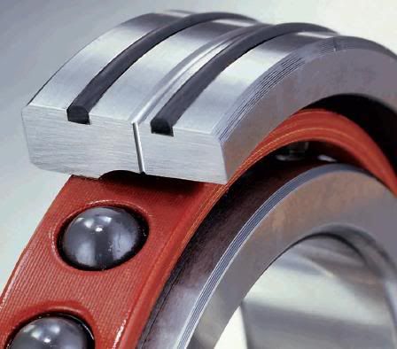
(Photo from UKF bearing catalog)
First time ever I've seen it. Now that everything is in pieces maby I should concider adding it to the top bearing. I don't think I'll get a bearing with integrated O-ring but it may be possible to do something similar with my plain vanilla deep-groove 6206 by making the grooves in the housing. I'll have to think about that.
I did add an aircoupling for positive pressure though. Now, all I need is a filter and low preassure regulator.
Thanks again!
/Henrik.
-
10-19-2007, 07:25 PM #59
Registered
- Join Date
- Aug 2007
- Posts
- 42
Hello Henrik
You could easily do away with a regulator for the positive pressure by just using a short plug and drilling a small hole in it (1~1.5mm) then feeding the air past it. A little trial and error (Making the hole shorter to increase the pressure)to achieve the desired pressure in the housing (Aprox 50-150kpa depending on how big the gaps are) is required but I use these on our machines to prevent fiddling fingers from over pressurising the housings and blowing grease out of the bearings.
The housing is the place for the O rings as I may have mentioned before as if mounted on the bearings they will wear the housing, not to mention the fact that you will need to get an odd ball bearing (= more $$$). I think the bearing pictured uses the O rings to seal some sort of pressurised lube system not for location.
Cheers
Daza
-
12-19-2007, 12:24 PM #60
Gold Member
- Join Date
- Aug 2006
- Posts
- 1602
Hi Henrik - have you made any progress since your last post?

 Reply With Quote
Similar Threads
-
BT30 Spindle cartridge for a smithy mill
By mlennon in forum Maintenance DIY DiscussionReplies: 0Last Post: 03-12-2013, 05:13 PM -
Looking for a BT30 Spindle
By xtwalt in forum Uncategorised MetalWorking MachinesReplies: 1Last Post: 11-20-2012, 10:10 PM -
BT30 Spindle
By dirtridn2010 in forum Tormach Personal CNC MillReplies: 0Last Post: 05-07-2012, 11:19 AM -
Reasonably priced BT30 ATC spindle.
By dwalsh62 in forum News AnnouncementsReplies: 0Last Post: 05-12-2011, 05:59 PM -
BT30 taper spindle for mold making
By grantmi1 in forum Hard / High Speed MachiningReplies: 5Last Post: 02-28-2006, 09:41 AM
