


I have been working on another piece of specialty CAM software, this time for machining mazes (i.e. toys). I found a bunch of maze generating algorithms on the Internet but had to come up with a different one to allow for easy conversion into g-code. Works quite nice so far, no other CAM needed. Some features it can do:
- 1 and 2 sided flat and cylindrical mazes
- g-code for slotting, undercuts and transition holes (the latter for 2-sided)
- 90-degree and 90/45-degree mazes
- programmable stay-off areas
It is still in prototype and I need to add a proper user interface and import features for images but, so far so good. This is a real fun project and will help me a lot with this years' Christmas presents.
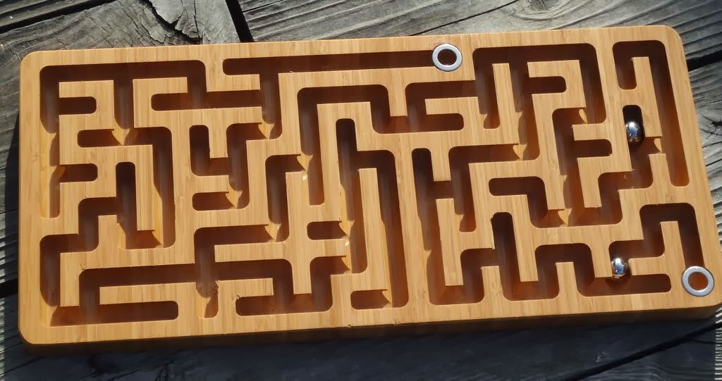
Simple 1-sided flat:
Cylindrical:
Just theoretical....I don't have a machine big enough to do that:

Thread: Maze CAM
Results 1 to 20 of 36
-
12-03-2013, 04:40 AM #1
 Registered
- Join Date
- Aug 2011
- Posts
- 999
Maze CAM
Box Joint and Dovetail CAM software here: WWW.TAILMAKER.NET
-
12-03-2013, 06:27 AM #2
Registered
- Join Date
- Jun 2012
- Posts
- 817
I just have to say that your projects always amaze me....no pun intended.

-
12-03-2013, 06:59 AM #3
Member
- Join Date
- Apr 2007
- Posts
- 8082
When I was traveling around Texas back in the late 70's to early 80's that's about what the state road map looked like to me.
 There was no such thing as civilian GPS at that time. Are you going to make your maze program available in some form to us non-programers? What size would that Texas maze be?
CarveOne
There was no such thing as civilian GPS at that time. Are you going to make your maze program available in some form to us non-programers? What size would that Texas maze be?
CarveOne
http://www.carveonecncwoodcraft.com
-
12-03-2013, 08:48 AM #4
Member
- Join Date
- Feb 2005
- Posts
- 829
DO Want!!
Keep us updated, because that looks amazing. The rings on that flat maze, are those just washers glued in? And what size bit and ball do you use in that maze.
-
12-03-2013, 05:02 PM #5
Registered
- Join Date
- Aug 2011
- Posts
- 999
I am planning to write a user interface for stand-alone use. Not complicated but that is the boring part of the project and may take a while. I hope to get that done in a few weeks. Originally Posted by CarveOne

I forgot the calculated size of the Texas maze but using a 1/2" ball and 1/4" walls it would probably be around 80"x80". You need a strong person to juggle that board
Thanks! The rings are indeed flat stainless washers to plug the start and end holes. I am not totally happy with this solution; a copper wire across the hole may look less obtrusive. Originally Posted by nlancaster
This maze has simple 1/2" steel bearing balls. The slots are pre-cut to 3/8" width with an end mill and the undercut ball channels finished with a 1/2" ball end plunge bit (1/4" shank). To allow for some clearance I run the ball channel 4 times with a tiny horizontal and vertical offset. I have also used 14mm glass marbles with a 5/8" ball end bit.Box Joint and Dovetail CAM software here: WWW.TAILMAKER.NET
-
12-03-2013, 09:40 PM #6
Member
- Join Date
- Apr 2007
- Posts
- 8082
Oh well ... Maybe I need a BB shot size cutter then.
Keep us posted on the progress.
CarveOne
http://www.carveonecncwoodcraft.com
-
12-03-2013, 11:00 PM #7
Registered
- Join Date
- Aug 2011
- Posts
- 999
Sure, I will post. Originally Posted by CarveOne
The smaller balls are actually possible but I am not aware of such small ball end plunge cutters for the undercut (except carbide ball burs?) but you could do a trench slot with a normal ballnose or end mill cutter and use smaller balls indeed. Might even look nice in acrylic but obviously the balls would fall out when turned over.Box Joint and Dovetail CAM software here: WWW.TAILMAKER.NET
-
12-03-2013, 11:07 PM #8
Member
- Join Date
- Dec 2004
- Posts
- 1316
Great work Jerry.
-
12-04-2013, 03:06 AM #9
Registered
- Join Date
- Feb 2006
- Posts
- 51
WoW! Amazing pics and very thought provoking.
At the risk of sounding stupid could you cut the raceways for the smaller sized balls with a straight bit or normal ball end then cut a duplicate top with slightly undersized slots to be glued over bottom. No undercutting required and the ball is trapped in maze.
"Hunker down for incoming fire "
Inspiring Thought for the Day:
Some people are like slinkies ... Not really good for anything....but they still bring a smile to your face when you push them down a flight of stairs.
-
12-04-2013, 03:44 AM #10
Registered
- Join Date
- Aug 2011
- Posts
- 999
Not stupid at all. Other people have been making mazes with acrylic cover plates. A cover plate with narrower slots is in principle possible. However, since it has no "body" to hold on to the cover plate would become a very fragile and wobbly piece to cut. Originally Posted by standles
Not needing any cover plate was a major motivation to go with undercuts, just a matter of simplicity and not getting dust trapped under a plexiglass plate. Practical maze toys would anyway better use larger balls. The huge complicated ones like the Texas example are more a kind of gag. they would be frustratingly difficult to solve without notes or tracking tools.
That said, such large mazes might make an interesting decorative texture/pattern (without real ball rolling purpose) for other objects; might be slotted or v-carved.Box Joint and Dovetail CAM software here: WWW.TAILMAKER.NET
-
12-04-2013, 07:32 AM #11
Member
- Join Date
- Feb 2005
- Posts
- 829
Stop chatting, back to work. We need this enough before Christmas to be able to use it!!
-
12-06-2013, 05:19 AM #12
Registered
- Join Date
- Aug 2011
- Posts
- 999
O.K., O.K., Originally Posted by nlancaster
I m working as hard as I can :cheers:
Well, not really. After all, I have a day job. So, there is no chance to get a working version done before Christmas.
However....I could generate a set of gcode files right away for a specific set of parameters, e.g. a one-sided orthogonal maze of 8"x12" outer dimensions to be cut with a 1/4" end mill and a 1/2" ball end plunge cutter. That would be easy to replicate on most CNC machines. Please let me know if that would be useful and I can post some files.Box Joint and Dovetail CAM software here: WWW.TAILMAKER.NET
-
12-06-2013, 08:27 AM #13
Registered
- Join Date
- Jan 2008
- Posts
- 1529
Jerry,
Looks great and I am interested in the finished product!
I suggest that you can probably get slightly smaller balls than the ball slot cutter (e.g 12mm balls, 1/2" cutter) to avoid doing multiple passes.7xCNC.com - CNC info for the minilathe (7x10, 7x12, 7x14, 7x16)
-
12-06-2013, 11:17 AM #14
Member
- Join Date
- Apr 2007
- Posts
- 8082
That would be better than watching you have all the fun. Originally Posted by JerryBurks
CarveOne
http://www.carveonecncwoodcraft.com
-
12-06-2013, 01:35 PM #15
Registered
- Join Date
- Mar 2011
- Posts
- 584
Way to one up us all again!
Great work!My CRP 48 x 48 build http://www.cnczone.com/forums/open_s...3-crp_4x4.html
-
12-06-2013, 06:13 PM #16
Registered
- Join Date
- Aug 2011
- Posts
- 999
Here it is
You will find three .tap gcode files in the zip:
mazegtopslot.tap - to be done with a 1/4" end mill. This cuts the start and end holes as well removes most material from the slots
mazegtopfinb.tap - to be done with a 1/2" ball end plunge router bit, will create the undercut for a 1/2" steel ball. (going with a 12mm ball to avoid the multiple cuts would shorten the machine time not that much, 2 passes must be done anyway because the bit must return from dead ends and multiple cuts will remove some of the fuzz). You can do this file with a normal 1/2" ballnose as well but won't have an undercut that way.
mazegtopstap.tap - optional, to be done with a small (e.g. 1/16" or 1.6mm) drill bit. This will create two diagonally offset holes at entry and exit and you can glue a wire staple in to block the holes
The blank should be 12" (300mm) in x-direction and 8.5" (215mm) in y-direction or more, at least 5/8" (16mm) thick or better 3/4" (19mm).
Zero is in the center of the top surface for all 3 files. I did not let it go too fast but if you have a slow machine you may want to edit the feed rate lines. Do an air cut first to check how it works. I did not have a chance to cut these files myself, so no guarantee is given.
It is a simple 10 x 14 cell one sided maze but might make a nice looking toy if cut from good hardwood. Plywood is not recommended, the ball end bit may rip the glue layer. I did not try MDF yet, it may or may not work.
 Box Joint and Dovetail CAM software here: WWW.TAILMAKER.NET
-
04-09-2014, 02:35 AM #17
Member
- Join Date
- Feb 2005
- Posts
- 829
Re: Maze CAM
Any word on this Jerry?
-
04-09-2014, 05:33 AM #18
Registered
- Join Date
- Aug 2011
- Posts
- 999
Re: Maze CAM
Oh my....I am embarrassed. I refined the functionality to make some more really cool mazes, see below. This is a wavy surface double sided maze with a custom outside shape (supposedly the outline of the State of Kentucky). The software generates the gcode for the channel slots and undercuts as well as the alignment holes for side flipping, the holes for the the transition blocker clips, the perimeter cutout and the perimeter chamfer. The wave surface warping is actually done in a separate step with another piece of software. Such a complicated one is not really practical for production though, 3 hours with 10 tool changes.....1/2" ballnose, 90-degree v-bit, 1/16" drill, 1/4" end mill, 3/8" ball plunge bit.... all from 2 sides. But a single side flat maze can be done in 20 minutes with 2 bits (or 3 with chamfer).
And I did really start on the user interface. Honestly....
But then I got an idea about a new smaller specialized CNC machine (still brooding about the details) and actually I dug out my project from last year for a void-less flat machined finger/box joint software.
I believe I am suffering from serious technological ADHD")
So, no promises about the maze software timing. But I am quite sure it will be this year.....

 Box Joint and Dovetail CAM software here: WWW.TAILMAKER.NET
-
04-09-2014, 05:35 AM #19
Member
- Join Date
- Feb 2005
- Posts
- 829
Re: Maze CAM
kewl looking puzzel.
I'll just be here to prod buttock now and then :stickpoke
-
04-09-2014, 10:29 AM #20
Gold Member
- Join Date
- Apr 2006
- Posts
- 3498
Re: Maze CAM
Jerry.. amazing work..I first saw your this maze in Talkshopbot forum. I am also a programmer but i salute your programming skills. Can you share the screenshot of GUI?
http://free3dscans.blogspot.com/ http://my-woodcarving.blogspot.com/
http://my-diysolarwind.blogspot.com/


 Reply With Quote
Similar Threads
-
maze to Printer - (maze of theseus)
By greenchair in forum 3D Printer / 3D Scanner DiscussionReplies: 0Last Post: 02-03-2014, 06:45 PM
