


Greetings Zoners!
I haven't been as active on the forums as I wanted, as meatworld has been a series of persistent problems that interfere with my bring all creative and buildy and what-not. However, I am also persistent and finally took advantage of an unusual situation (the spike in Bitcoin prices) to fund a project I've wanted to do for a while:
A complete, self-contained, stand-alone CNC controller assembly to power my Zenbot 1216 tabletop machine.
I started by acquiring the parts I knew I wanted. I knew I wanted the unit to be rackmount, and I've used Bud Industries' rackmount chassis before for other projects, so I purchased a 4U aluminum chassis (which comes as front/back/sides) and the top and bottom panels (undrilled ones - they also sell ventilated but I didn't want that and you'll see why in a bit!) and handles for it. The chassis is a simple screw-together assembly so I assembled everything except the lid and set that aside.
I knew I'd need a crapton of hardware to mount everything, so a quick trip to McMaster-Carr's site produced an order of 6-32 self-clinching studs, flange nuts (which have a lockwasher-esque grooving ring cut into their flanges), and flat washers. The studs are neat - they have a flat head that has tiny little tines around its periphery that dig into the material and basically lock the stud into place. This has the effect of allowing me to mount things to the chassis' bottom panel without having screw or bolt heads sticking out that can snag on things. This will be an important consideration when it comes time to mount the contraption...
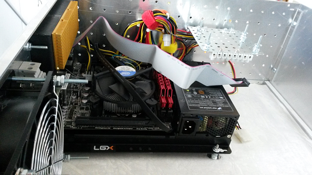
I also acquired the parts for the control PC. I wanted a mini-ITX form factor for size, and since I wanted the PC to be beefy enough to do more than just act as a device to run CNC software I selected an Intel I5-4570 processor as the brain. 8 gigs of RAM would be more than enough to hold Windows 7 without having to play swapfile hoedown, and a 750GB notebook hard drive would be more than enough to hold even the largest design catalogs. For the mobo I selected Gigabyte's Z87N-WiFi, which is a solid middle-of-the-road mobo with integrated WiFi and support for Intel's integrated graphics since I don't need a high-end graphics card for this application.
Mounting the mobo in this application would be, well, let's go with "interesting" so a search turned out a nice little thing made by LGX: the CT100 "mountable open case." It's basically a mobo mounting plate with additional places for various connectors and switches and an underside mount area for two 2.5" (laptop-style) hard drives or SSDs. It also includes a small area to mount a Flex-ATX style mini PSU.
Now that the PC component selection is sorted, let's pick out other goodies...
Powering the steppers would be somewhat important if we want a CNC mill to actually move, so the magic there would be handled by the perennial favorite, the Gecko G540. Since my Zenbot 1216 uses 24-volt steppers a basic 24V 14A switching supply will handle that aspect, and since the mobo doesn't include a parallel port I also snagged a USB SmoothStepper to interpolate for the G540.
On the spindle side, I had built a custom spindle system (which I'll detail in its own article) for the Zenbot that uses a 24V 17A brushed DC motor. To power that, I obtained another 24V power supply, this time rated for the 17A the motor caps out at. I wanted the spindle motor to be controllable through the G540's VFD control port, and some research led me to Pololu's 24V23 motor controller board - it can communicate through USB and can easily handle the spindle motor's drive requirements, and it can be configured to use a VFD-esque control scheme. I already had a heatsink to mount it onto, so that was a pretty straightforward selection process.
Once everything arrived - 14 packages in all, my mail carrier really loved me that week... - it was time to make with the buildin'.
The PC build was pretty straightforward despite the whole thing being less than a foot square. The hard drive mounts to the underside so it's out of the way, and some velcro strips that Gigabyte includes with the mobo helped tie-wrap the cabling into a small-ish bundle so it's out of the way.
With the PC built, it was time to benchtest it. This is a no-CD build, though, so I had already built a USB install of Windows 7 Professional (it's nice having a MSDN subscription and full deployment tools...) and set the mobo to boot from USB. Front-panel cables stolen from an old ATX tower case served to connect some LEDs and the power/reset switches to the mobo. Shockingly enough, it booted on the first try! So, about half an hour later Windows was pulling down its customary stupidly large number of updates. I let Windows finish its preliminary setup and shut everything down in prep for the next step.
The first step in mounting anything in a limited amount of space, let alone several anythings, is to do a rough layout to test where things can be placed. I wanted a few specific things in the front and back, and wanted to keep the AC supply lines limited to a specific area, so I laid the chassis out with the power supplies on the left, the PC on the right, and two cooling fans positioned to flow air through the chassis diagonally. The front fan would draw air in, and the rear is exhaust, so that the heat from the various parts of this thing would be handled aggressively.
Toward the center-front, I planned to mount two solid-state relays. One of them would be tied to the PC's PSU so that it turned on when the PC did. This would then feed the cooling fans and the two power supplies for the steppers and spindle. The second SSR would connect to output #2 on the G540, and allow for automated control over a 120VAC device like a coolant pump.
I wasn't sure where to mount the SmoothStepper, but in a flash of inspiration I thought it could mount onto a small shelf over the PC where it would be accessible but out of the way, so a quick trip to the local hardware store was in order. As it turns out, you can buy ready-made pre-drilled steel plates and angles that are reminiscent of the old-school Erector set's pieces, so a plate and two angles would do rather nicely for holding the SmoothStepper. Underneath this shelf, I mounted a terminal strip that was connected to the wires of a hard-drive power 'Y' adapter - this would provide taps to power the SmoothStepper (so as to eliminate the glitchiness problem some have reported when running it off USB power) and to feed to the SSR that would switch on the fans and power supplies.
Since I have access to a vinyl sign cutter, I took advantage of the supplies thereto by covering the front, back, and bottom panels of the chassis with transfer tape, which is basically two-foot-wide masking tape. I then worked out where to mount everything on the front and back panels, how big to cut the holes, etc. and punched out the appropriate bits.
]
The front panel received an oh-crap, er, emergency-stop button, two LEDs to indicate when the spindle and stepper power supplies were powered up, two LEDs for the PC (read: power-on and hard drive activity), and the power and reset buttons for the PC. I used the vandal-resistant heavy duty buttons for those so they can handle abuse, and I used an extended-actuator button for power and a recessed one for reset so they can be operated by feel. The fan received a cleanable mesh filter to catch debris and prevent the sucking of bad things into the inner workings of the control box.
The back panel was cut out for the PC's backplate, the G540, and cooling fan. Holes were added for the inputs and outputs from the G540 (all of them), and high-current passthrough fittings for the spindle motor power. A power inlet with a built-in switch allows for easy AC hookup, and two auxiliary outlets allow powering up other things - one of these is switched by the second SSR that's controlled by the G540, and the other is a direct-wire to the power inlet.
A quick closeup shows the back-panel connections more closely. A ribbon cable connects the G540 with the SmoothStepper inside, so I carved out a slot for that and trimmed it out with some grommet strip for cable safety. The topmost gray connector in the center is the connection for the spindle motor. Below that is the E-stop-slash-limitswitch input - this has to be jumpered to enable the G540, so it'll be wired to the limit switches on my Zenbot as well as to a secondary emergency stop switch I'll mount on the machine proper. Below that is a three-pin connector that hooks to the G540's outputs (and includes a supply lead for convenience) and finally there's a 5-pin input connector (with supply lead as well) for adding home switches, etc.
Once I had the back panel cut out for the PC backplane I was able to mount that to the bottom panel of the chassis, and I used some extra nuts as spacers so it was high enough to clear the rolled edges of the bottom panel. Basically, to remove the bottom panel I just remove the screws that connect it to the chassis' sides and tilt the whole front/sides/back up and away.
After that, I was able to work out where to mount the rest of the electronics. I left areas at the left-rear (top-left in the picture) to clear the exhaust fan, the left-front (bottom-left in the pic) for the AC terminal strips and AC wiring, and right-front (bottom-right) for the front intake fan.
As I mentioned, I used self-clinching studs and flange nuts for mounting everything so there were no protruding fasteners. I added a ground stud near where I planned to run the AC connections.
With the chassis front/back/sides as a unit, I then wired up the front and back panel connections. For the back this entailed running leads from the connectors for inputs and outputs to the G540, and wiring up the AC sockets.
For the front, this involved wiring up leads to the E-stop switch, power and reset buttons, LEDs, and fans. I used a lot of peel-and-stick nylon tie-wrap mounts and short tie wraps to bundle and neaten the wiring. Cables were then routed down the sides from both the front to the back for the PC connections, and from the back to the front for the AC connections.
Once all the finicky work was done, I reassembled the chassis (sans top panel, obviously) and triple-checked my handiwork. I added a bracket-mounted USB connector that plugs into the mobo to provide internal USB connections, and plugged the SmoothStepper and Pololu motor controller into that. I also used 12-gauge speaker wire to run leads from the stepper power supply to the G540, and from the spindle power supply to the motor controller and then to the bulkhead terminals. I also connected the SmoothStepper and one SSR to the PC's power supply so that both would be powered up when the PC is turned on.
With that done, I turned my attention to the AC wiring.
I couldn't get a decent pic of that, but the gist of it is that I used two 8-position barrier strips, one for the neutral connections and the other for the hot. jumper wires made all terminals on each strip active, and all of the neutral connections from the power supplies and AC outlets went to one strip. The hot-side strip was wired with two leads connected to the AC inlet's hot lead. One went to the PC's PSU and the other went to the switched-AC side of the SSR connected to the PC's PSU. The return lead from the SSR then fanned out to connections for the hot-lead terminals for the cooling fans and spindle/stepper power supplies as well as the switched outlet. When AC is applied, the PC is powered up directly, and when it's turned on it turns on the SSR which subsequently turns on the fans and power supplies - everything thus switches on from a single button.
With everything wired up, I did some sanity checks with a multimeter. I checked for shorts and resistance to ground across all AC leads and sockets, and once I was satisfied there were no potentially dramatic electrical anomalies I then plugged in an AC cord and flipped the AC inlet's master switch. No magic smoke released!
I crossed everything I could cross and pressed the power button for the PC and it fired up, as did the SSR, fans, and power supplies. I love it when things actually work as planned!
Another thorough check was in order, and everything was copacetic - no magic smoke release, no hotspots (electrical or thermal), and the software running on the PC was seeing and talking to everything. So, the time was nigh for connecting it to the Zenbot!
In order to protect the work area of the Zenbot I laid a large board onto the mill, and screwed down a sheet of acrylic. I connected the control box to the Zenbot and sure enough, I could move the gantry. It took some fiddling with settings to make the motor controller work the spindle motor properly, but once that was done I was able to switch Mach3 to MDI mode, type in S5000 and M3 and have the spindle fire up. So I stopped it, E-stopped the machine for safety, and chucked an endmill into the spindle. Repositioned, took off E-stop, and sent the G-code to cut a rectangle.
The Zenbot moved like it had a purpose, and sliced through the acrylic like it wasn't even there. it also sliced through the lumber as well - guess I need to adjust the settings on the Z axis.
The next part of the build will be modifying my cart o' Zenbot to accept a rackmount enclosure so that the entire machine is in one mobile cart. Perhaps, in another write-up...
I wonder if there'd be enough interest in these to make and sell 'em as ready-to-go turnkey CNC control systems...
Results 1 to 2 of 2
-
02-02-2014, 09:57 PM #1
 Registered
- Join Date
- May 2011
- Posts
- 20
Custom CNC Controller System In A (Rackmount) Box! (LOTS of pics!)
-
12-22-2022, 02:24 PM #2
Member
- Join Date
- Dec 2022
- Posts
- 1
Re: Custom CNC Controller System In A (Rackmount) Box! (LOTS of pics!)
And that’s only if you’ve already built an emergency fund and know crypto investments won’t get in the way of long-term goals like paying down high-interest debt and investing in low-cost index funds or new altcoins like full send crypto. There are over 17,000 types of cryptocurrencies as of February 2022, according to the price-tracking website CoinMarketCap. Bitcoin makes up nearly half of the total crypto market cap, and Ethereum makes up nearly a quarter. To get started in cryptocurrency investing, create crypto exchange accounts to start buying and holding altcoins.


 Reply With Quote
Similar Threads
-
My SX2 CNC build! (lots of pics)
By asifjahmed in forum Benchtop MachinesReplies: 37Last Post: 04-15-2016, 06:31 AM -
pc motion controller for custom system
By hpghost in forum Controller & Computer SolutionsReplies: 4Last Post: 08-01-2013, 05:26 PM -
Help please, shallow DOC sucks noodles... LOTS OF PICS!
By Propaganda in forum PCB millingReplies: 13Last Post: 07-15-2010, 04:52 PM -
M.E. Project (pics, lots of pics)
By skmetal7 in forum Community Club HouseReplies: 2Last Post: 01-08-2007, 10:30 AM
