


First off, thanks to all who helped in the "Hoping it works" project. I have retired l'il guy since it was a "getting familiar with cnc" project but has since built 2 more machines with larger cutting capacity and using surplus linear rails.
I still use the Xylotex 4-axis box but have modified it to be able to switch the stepper motor lines (with the Xylotex controller power OFF) from one machine to the other using toggle switches. This modification required transferring to a bigger enclosure (an old IBM desktop computer's), longer and bigger wires to the steppers (12 feet to one and 16 ft to the other using 18 ga. wires) and adding 2 independently powered 24v. cooling fans directly blowing on the 4-Axis chips.
The problem with this set-up is that I can only use one cnc machine at a time thus I've finally embarked on putting my Xylotex 3-axis board in operation. My problem now is in the power supply stage and here are the parts (from dump diving) that I have.
1. 220/24VAc - 8amps transformer
2. Bridge rectifier
3. 11,000 uF/400vdc and 41,000 uF/30vdc capacitors
My VOM measured voltage reading at transformer secondary is 25VAC, after the rectifier is 23VDC and 32VDC with either of the capacitors!
Can somebody please tell me how I can drop the 32VDC down to the Xylotex board required 30VDC? Do I need to since the board capacity is 35VDC with BEMF? Will using 32VDC be cutting it too close?
Thank you for any help extended.
Results 1 to 20 of 23
-
09-30-2007, 09:18 AM #1
 Registered
- Join Date
- Jul 2004
- Posts
- 87
 Building a Power Supply..questions
-
10-01-2007, 12:04 AM #2
Member
- Join Date
- Dec 2005
- Posts
- 1408
Dear Guy Smiley, Originally Posted by Guy Smiley

No expert, but here my two cents..
1) The transformer. Transformers are rated to give a known AC secondary voltage at a known current. If your transformer is rated at 8 amps, it should deliver a secondary AC voltage of about 24 volts when it is asked for 8 amps AC. If it is asked for less AC current at the secondary winding, the AC voltage it delivers will be greater. Transformer manufacturers give a figure for "on load" and "off load" regulation. With a reasonably beefy transformer like yours, it might be (say) 7% to 10%. What that means is that if the transformer has a really light current demand, the secondary AC voltage might increase by as much as 10%. That puts the AC secondary voltage up to about 26.4 volts AC at no load, and should stay at the same 24v AC at 8 amps.
2) Bridge rectifier and capacitor.
Having passed through the bridge rectifier and capacitor, whatever the AC voltage is at the secondary output of the transformer, it will be transformed into a DC voltage which is
1.41 as large as the AC voltage
What this means is that 24v AC at the output of the transformer (working full stretch) will become about 33.8v DC. If however there is no load, the DC output will be 37v DC.
The value of the smoothing capacitors do not really affect the DC voltage (within reason). All they do is affect the ripple voltage about which the average DC voltage value flickers.
Sorry, there are whole websites that can explain this better... (had to try though..)
Best wishes
Martin
-
10-01-2007, 12:54 AM #3
Community Moderator
- Join Date
- Dec 2003
- Posts
- 24221
One of the simplest ways is if it is possible to remove a few windings to suit. Originally Posted by Guy Smiley
Typically the turns/volt is around 2 to 4.
If you want to get a more exact idea before you proceed, put around 10 turns of enameled wire over the top of the present secondary and measure the AC voltage, this will enable you to find out how many turns/volt the transformer possesses .
Then remove the amount of turns you want in order to reduce the secondary to what you want it to be.
Secondaries are almost always wound last, or it might even be side-by-side with the primary.
Al.CNC, Mechatronics Integration and Custom Machine Design
“Logic will get you from A to B. Imagination will take you everywhere.”
Albert E.
-
10-01-2007, 04:29 AM #4
Registered
- Join Date
- Jan 2007
- Posts
- 355
If you're not comfortable with rewiring the secondary, you can also wire a few diodes in series with the bridge rectifier. Each diode will drop about .7 volts.
Make sure that the diode's current rating exceeds the maximum current draw.
I would also be be concerned with the 30 volt capacitor.
It's not a good idea to exceed the capacitor's voltage rating. Opt for a higher voltage capacitor.
-
10-01-2007, 07:26 AM #5
Registered
- Join Date
- Jul 2004
- Posts
- 87
Thank you Martin and compared to me you are the expert. Now I understand , what's going on, a little better. Originally Posted by martinw
Basic electronics in college has been about 30 years ago, I'm 50 now, so I have to brush-up on the E=IR and the rest. Only rule I go by right now is to mind polarities and so far it kept me from blowing anything up.
Load capacities are a different story though. I'm quite limited with what I've acquired from my dump dives of disabled computer printers and power supplies plus an old 20A transciever PS (I'll work on this later as the higher AMP rating scares me).
-
10-01-2007, 07:37 AM #6
Registered
- Join Date
- Jul 2004
- Posts
- 87
Thank you for that info Al. I haven't even attempted this but will on one of my smaller ones first. I'm such a fraidy cat when it comes to electricity but will surely explore this on one of my "higher confidence" nights. Originally Posted by Al_The_Man
-
10-01-2007, 07:48 AM #7
Registered
- Join Date
- Jul 2004
- Posts
- 87
Thank you Eurisko. I'll definitely try this one now as I'm a little more comfortable with this. One question though. Can diodes, of lower amp (4Amp) rating, be paralleled then connected in series to handle the 8amp rated output of the bridge rectifier? Originally Posted by Eurisko
I'll heed your warning about the 30v cap and will just use it when I put together a 13.8VDC PS.
-
10-01-2007, 07:54 AM #8
Member
- Join Date
- Jun 2007
- Posts
- 3757
 Don't forget to add a fuse or 2 on the secondary DC or AC side. Originally Posted by Guy Smiley
It might save a bit of smoke and surprises, or a fire!
Good quality screw connections are preferable to spade lugs.
Have you ever seen how hot a loose spade lug can get?Super X3. 3600rpm. Sheridan 6"x24" Lathe + more. Three ways to fix things: The right way, the other way, and maybe your way, which is possibly a faster wrong way.
-
10-02-2007, 12:13 AM #9
Registered
- Join Date
- Jan 2007
- Posts
- 355
Guy,
Wiring diodes in parallel for more current can be a little tricky.
If the forward voltage of the diodes is not perfectly matched, one diode will draw more current than the other.
One workaround is to add a small value resistor in series with each parallel leg. This tends to minimize the differences in the diodes.
If your transformer puts out 24vac @ 8 amps, the most current you'll draw is approximately 5.5 amps @ 34 vdc.
You'll have to experiment with resistor values;
A .1 ohm resistor will drop .3 volts @ 3 amps. It will dissipate .9 watts.
Try different resistor values to balance the current in each parallel leg.
Our simple voltage dropper has grown to 6 (or more) diodes and 2 resistors.
May be easier to rewire the secondary.

-
10-02-2007, 12:45 AM #10
Member
- Join Date
- Jun 2007
- Posts
- 3757
 If it is difficult to remove turns from the transformer you can ADD in anti-phase so that the voltage from the extra turns SUBTRACTS from the total voltage. Minimum wire diameter: Don't exceed 3 amps per square millimeter. Normal is 2.5 but because on the surface and ventilated, a few more losses won't hurt. Originally Posted by Eurisko
Super X3. 3600rpm. Sheridan 6"x24" Lathe + more. Three ways to fix things: The right way, the other way, and maybe your way, which is possibly a faster wrong way.
If it is difficult to remove turns from the transformer you can ADD in anti-phase so that the voltage from the extra turns SUBTRACTS from the total voltage. Minimum wire diameter: Don't exceed 3 amps per square millimeter. Normal is 2.5 but because on the surface and ventilated, a few more losses won't hurt. Originally Posted by Eurisko
Super X3. 3600rpm. Sheridan 6"x24" Lathe + more. Three ways to fix things: The right way, the other way, and maybe your way, which is possibly a faster wrong way.
-
10-02-2007, 12:47 AM #11
Member
- Join Date
- Dec 2005
- Posts
- 1408
Dear Guy Smiley, Originally Posted by Guy Smiley
Safe work.
Best wishes
Martin
-
10-02-2007, 03:49 AM #12
Registered
- Join Date
- Jul 2004
- Posts
- 87
Oooops, I guess I'll dump that parallel diode idea. I'll try and look for some 6A diodes here and stick to series. Originally Posted by Eurisko
GS<<
-
10-02-2007, 04:16 AM #13
Registered
- Join Date
- Jul 2004
- Posts
- 87
I have to apologise for my inadequacy but please help me with this part. I don't have any idea on fuse rating for secondary AC line. Is it better to put a fuse on AC or DC or both? I'm sorry again and appreciate help on this. Originally Posted by neilw20
-
10-02-2007, 04:42 AM #14
Registered
- Join Date
- Jul 2004
- Posts
- 87
Thank you Niel. "Anti-phase" though is beyond my knowledge at the moment but I'll try and research it now that I know of its existance. Originally Posted by neilw20
-
10-02-2007, 04:54 AM #15
Registered
- Join Date
- Jul 2004
- Posts
- 87
LOL! Thank you Martin! You experts will laugh if you can just see me everytime I try to power-up! And yes, I do remember to unplug from the AC source and drain the capacitors using a cooling fan before working on whatever new info that's kindly contributed here. Originally Posted by martinw
-
10-02-2007, 05:43 AM #16
Registered
- Join Date
- Jul 2004
- Posts
- 87
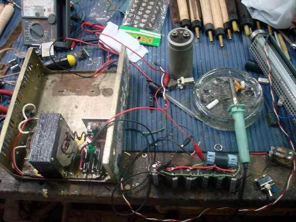
Power Supply Project
Here's a photo of the PS project. Excuse the mess and amateur work.
-
10-02-2007, 05:51 AM #17
Registered
- Join Date
- Jul 2004
- Posts
- 87
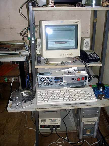
Xylotex 4-axis box project
Here's the recently, put in operation, Xylotex box mod. Transferred all the inards of the Xylo 4-axis controller into an IBM desktop computer box then added a blower, directly blowing on the axis chips, and an exhaust fan. The 2toggle switches to the left control the fans as they're independently powered. The 4 toggle switches in the middle are to switch to whichever machine I need to use.
-
10-02-2007, 06:01 AM #18
Registered
- Join Date
- Jul 2004
- Posts
- 87
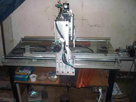
Machine 1
Here's the 4-axis I built right after "L'il Guy". I used surplus linear shafting on the X&Y. It's due for rework though since I shouldn't have used the Y&Z shafts and the Y&Z drive screws as structural members. I've acquired some surplus THK linear bearings and rails to replace the Y shafting.
-
10-02-2007, 06:10 AM #19
Registered
- Join Date
- Jul 2004
- Posts
- 87
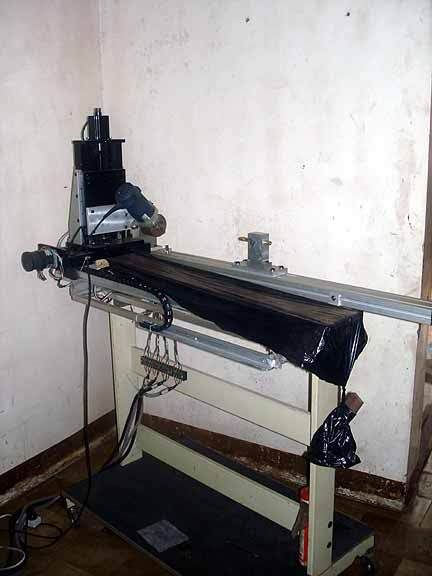
CNC Machine 2
Here's a recently put in operation, but not completely finished, 4-axis machine. I found some linear stages in one of the surplus/machine parts recycler store and found a way to put latch them together. This is a dedicated pool cue machine and that's the reason for the work area capacity of X=40" Y=3" Z=4" and a high resolution A-axis. I also used the base of a plotter for this. The black X-axis covering acts as a dust cover and just made from plastic trash bag material, smoothened wood dowel (at the far end of the axis and currently just a piece of wood to pull the cover taut and travel with the axis.
-
10-06-2007, 02:16 AM #20
Registered
- Join Date
- Jan 2007
- Posts
- 355
Guy,
Your power supply project photo looks exactly like my dining room table.
All kidding aside, nice work on the machines.
My brother used to repair cue sticks on an old atlas lathe. He would have loved to have your 4 axis machine.

 Reply With Quote
Similar Threads
-
Building my power supply
By quamit in forum Gecko DrivesReplies: 1Last Post: 09-18-2007, 05:49 PM -
building power supply
By heilcnc in forum CNC Machine Related ElectronicsReplies: 7Last Post: 04-14-2006, 06:29 AM -
Building a power supply with decent volt/amperage
By phantomcow2 in forum CNC Machine Related ElectronicsReplies: 4Last Post: 03-14-2006, 11:33 PM -
Building a power supply
By WilliamD in forum CNC Machine Related ElectronicsReplies: 5Last Post: 10-20-2005, 04:08 PM -
Building a Power Supply
By xairflyer in forum Hobbycnc (Products)Replies: 9Last Post: 02-07-2005, 11:04 PM
