


Yes it has a spring. The force can he higher if you are probing with a spherical tip or on hard materials. I would quite like to try magnets at some point.
Graham
Thread: homemade 3D touch probe?
Results 21 to 40 of 56
-
06-09-2004, 03:01 PM #21
 Registered
- Join Date
- May 2003
- Posts
- 340
-
06-22-2004, 09:53 PM #22
Registered
- Join Date
- Mar 2004
- Posts
- 500
Hi, how exactly do you use the points after they have been stored? Can you load them into AutoCAD?
Thanks.
-
06-22-2004, 11:58 PM #23
Community Moderator
- Join Date
- Feb 2004
- Posts
- 2337
Graham, I saved your page as a pdf file. Would you mind If we also posted it in this forum as a downloadable demo? All credit would go to you.
Here is a sample of what I mean.
If you find this acceptable, could you please upload this file to here
http://www.cnczone.com/modules.php?s...ownload&cid=16Being outside the square !!!
-
06-23-2004, 01:39 PM #24
Registered
- Join Date
- Mar 2003
- Posts
- 270
If you are using DeskCNC as your controller, the automated probing routines will automatically create an .stl file of the scanned surface. The surface is corrected for the radius of your probe tip, and the small oscillations caused by axis parallel scanning are filtered to create a smooth surface. The routine incorporates a simple dialog and jogging to set the range of the surface to scan, it has adjustable scan granularity at the step level and a velocity parameter is available. Entering the scanning parameters results in automatic calculation of the size of the scan steps, number of points, and estimated final file size. When the scan is in progress, each line is drawn on the display, and an estimate of completion time is displayed. The controller uses the same accel/ramping settings for scanning as for machining.
After the DeskCNC scan is completed and the .stl file is saved, it can be reopened in the .stl machining cam section, where it will be shown in wireframe or as a fully rendered and shaded surface. Various milling strategies can then be applied to the surface to create toolpaths to machine a duplicate or similar part.
Fred Smith - IMService
http://www.cadcamcadcam.com
-
06-23-2004, 02:22 PM #25
Community Moderator
- Join Date
- Mar 2003
- Posts
- 35538
Not directly into AutoCAD, but I believe you can load them into Rhino.Originally posted by Sanghera
Hi, how exactly do you use the points after they have been stored? Can you load them into AutoCAD?
Thanks.
Gerry
UCCNC 2017 Screenset
http://www.thecncwoodworker.com/2017.html
Mach3 2010 Screenset
http://www.thecncwoodworker.com/2010.html
JointCAM - CNC Dovetails & Box Joints
http://www.g-forcecnc.com/jointcam.html
(Note: The opinions expressed in this post are my own and are not necessarily those of CNCzone and its management)
-
06-23-2004, 08:19 PM #26
Registered
- Join Date
- May 2004
- Posts
- 60
You may find this useful, this is what I know (worth all two pesos)
To learn how to import into Rhino I wrote a vbscript to output a x,y,z coordinate point for each place an imaginary digitizing routine ran by Mach2 would create a point. This way x & y are fixed at a set interval and the z is suppossed to be where the tip stopped.
Some translation (another script) would be needed to convert the Mach2 output into one suitable for Rhino, but my purpose was to make sure I could get a surface first, script is secondary and should be easy enough. I bought a Microscribe since so no need to continue developing this method, but I could help you with the script part as well or Excel would work too.
Attached is a zip of the text file that can be copy/pasted into Rhino (takes a little time) and a screenshot. Its using the ! SrfPtGrid command. Also included is a screen shot of the perspective view rendered.
Cliff
-
06-26-2004, 01:17 PM #27
Community Moderator
- Join Date
- Mar 2003
- Posts
- 35538
Here is a free program to convert the points to .stl and other formats.Originally posted by Sanghera
Hi, how exactly do you use the points after they have been stored? Can you load them into AutoCAD?
Thanks.
http://www.paraform.com/ppdl/index.htmlGerry
UCCNC 2017 Screenset
http://www.thecncwoodworker.com/2017.html
Mach3 2010 Screenset
http://www.thecncwoodworker.com/2010.html
JointCAM - CNC Dovetails & Box Joints
http://www.g-forcecnc.com/jointcam.html
(Note: The opinions expressed in this post are my own and are not necessarily those of CNCzone and its management)
-
01-28-2014, 06:58 PM #28
Member
- Join Date
- Jul 2003
- Posts
- 168
Well, that was a nice nap...
As soon as I woke up, I finally designed and built something of my own. I think I dreamed it.
Unfortunately, I'd forgotten about this thread and posted it in another:
http://www.cnczone.com/forums/cnc_to...uch_probe.html
Beware, it works, but it's only for probing in the Z direction: if it encounters resistance in X or Y moves, it will break or bend something.--
Dan
-
01-29-2014, 01:23 AM #29
Member
- Join Date
- Sep 2006
- Posts
- 6463
Hi, wow, 10 years between posts....that's a long design gap.
As I'm just getting into CNC milling, I looked at the aspect of generating the info for the mill to be able to copy a part by probing the surface with a needle like probe tip and being able to probe non electric surfaces like wood and plastics etc.
One thing that worried me in the design part, what if the probe contacted a steeply sloping face like the start of a curved surface.....it would deflect the tip sideways before the spring pressure made contact.
I think that a probe that deflects sideways on contact would have a better chance to detect the surface profile.....each time the Z went down if the tip contacted the start of a curve which is like a steep sloping angle plane, it would move sideways and so indicate a contact at the point provided the ratio of the sideways movement was large compared to the depth movement.
This means that the slightest (as in .02mm sideways) movement would make contact inside the device the moment the Z came down and touched the piece to be probed.
I've come to the conclusion that to probe with a part in the mill and using the mill head Z axis to go up and down a million times to get the resolution for fine profile work would be like using a sledge hammer to crack a walnut.
In that case I think a small special purpose probing mill should be the machine to obtain the info for the main mill to produce the copied part.
A probing mill only needs to be small and lightly built and to have some X, Y and Z slides that can be moved the same as a main mill (but on a much smaller scale) with small steppers like a printer, and only needs to be able to move the part (or the probe) for the probe to sense the profile.
With no machining needed, the probing mill could be very lightly built with just unsupported linear bearings on hardened round steel rods for the slides.
I looked at the workings of a lever type dial indicator and see the multiplication factor of the inside levers and the tip movement gives it the ability to read a deflection of .02mm with ease.
So as the probe would always be moving sideways as it went down, the dial indicator type movement would always be detecting the side ways movement the moment it touched the work piece, but in place of moving a needle on a dial face it would make electrical contact instead.
This means that if the probe moved .02mm sideways on contact and the needle moved 1mm on the dial face, this would give plenty of space to put contacts in without going to watch making proportions.
A lot would depend on the cost of a ready made bought item as opposed to a DIY one.
This is something that I'm working on as I know I'll have a need to detect the profile of a work piece when the time comes, even a relatively coarse piece of work will pay dividends.
My last doodle/design was with a needle probe that interrupted a light gap at it's top end and detected the needle up and down movement more finely than the sideways movement.......... and the stylus of a record player can also detect very fine movement too.
Ian.
-
01-29-2014, 01:42 AM #30
Member
- Join Date
- Jul 2003
- Posts
- 168
handlewanker?? [stops. reads: "Australia." oh... ;^) ]
Hey, Ian,
Greetings! (from the Future!) I almost dozed off before seeing your response. Thanks for that btw!
Yes, that's two clever ideas in one post: a dedicated light-, hold a mo' let's say, appropriate-weight proberizer CNC--but of course I have to remind you of your sledgehammer/walnut observation. Still could be worthwhile, if the number of models to be scanned is large enough. And secondly, taking perverting, hold, converting an existing sensitive movement to another purpose. (No, three ideas: putting the model to be scanned in a record player--which I think is a FIRST for cnczone. ;^) )
I don't know what a lever-type dial indicator is--but I've been asleep--because I can't picture what this means:
Throw a pic up when you can. Or keep your own counsel. I'm all for whatever gets something real out of you in under 10 years!So as the probe would always be moving sideways as it went down, ...
Cheers! (and thanks, again.)
--
Duh Zane--
Dan
-
01-29-2014, 05:47 AM #31
Member
- Join Date
- Sep 2006
- Posts
- 6463
Hi, yeah, what's in a name......as I said I'm very new to CNC as in what's Gcode Mum?.....LOL.....but as I'm expecting delivery eventually of an SVM-0 mill from the Skyfire build thread, I quickly realised that if you want to make parts you gotta have a plan, and that means either generating the G code by Cad/Cam process or probing an original part......the latter can be modelled in any material and then translated to CNC savvy coding when the final design is formalised.
Having looked at the process it boils down to getting enough points of reference for the cutter to move smoothly and generate the profile etc.
I seem to remember in another thread that a probe was made by a Dutch fellow that moved in all directions, up down and sideways, similar to a gymbal motion.... it was a longish spring loaded rod that moved a plate and made contact no matter which way it moved etc.
I think it was a copy or derived from a commercial one so as it was quite simple it probably won't be all that expensive.
I'll have to find out more on how touch probes work....no sense in re-inventing the wheel.
I'm still puzzling over how a probe senses the steep sides of a sphere without deflecting off before recording.
If the probe relies on up pressure to make the "switch" work it will mean there is undue pressure before the probe works and coming down against a sloping face will be a bit iffy.
I looked at the design for an EDM and the way the sensing head retracts immediately the contact was made.
Although in the EDM design it's an electrical contact, having a fine and sensitive switch in the probe could make the contact pressure very slight and give a good indication the moment contact is made.
Ian.
-
01-30-2014, 04:07 AM #32
Member
- Join Date
- Jul 2003
- Posts
- 168
"The computer ate my reply..." which among other things had this link, I had to go hunt up again. Let me stick it here before I misplace it again:
3-Sweep: Extracting Editable Objects from a Single Photo, SIGGRAPH ASIA 2013 - YouTube
I was hunting for something on the subject of '3D modeling from photographs' when I stumbled on that presentation ('a human-assisted 3D model from a single photo'). I was hunting (and AutoCAD's Autodesk 123D - Free 3D Modeling Software, 3D Models, DIY Projects, Personal Fabrication Tools is one of the best-known) to make sure you knew about the technology, which can--under ideal conditions--create good 3D models from a set of (some 30 to 60) photos taken from slightly different perspective. While you can buy software to do it (photomodeler.com), there are a number of websites which offer to do it for you if you'll upload your photos. (They are collecting a set of models for presumptive re-sale at some future date.) If you don't know about it, you'll want to look into it before sinking a boatload of money or effort on a sophisticated prober machine. (The aforementioned 123dapp.com is one, and cubify.com is another.)
Okay that's out of the way.
Really "getting enough points" for the "point-cloud-processor" software to generate an acceptable model. Originally Posted by handlewanker

Love to see it if you can find a pointer to it. (I'll be hunting for "Dutch" and "gimbal".)I seem to remember in another thread that a probe was made by a Dutch fellow that moved in all directions, up down and sideways, similar to a gymbal motion.... it was a longish spring loaded rod that moved a plate and made contact no matter which way it moved etc.
They first have to come in physical contact and that contact has to produce a change in voltage (high-to-low or v.v.) which can be sensed on a pin on a parallel port.I'll have to find out more on how touch probes work....no sense in re-inventing the wheel.
I disagree that if a probe uses pressure, it necessarily means it will be undue. In the case of the Renishaw-style probes that feature three radial rods resting on a pair of ball bearings each (pressed against them by a spring force actually) with an electric current runs through them which is interrupted if the contact is broken, light touches breaks one or more of the point contacts, signaling a touch.I'm still puzzling over how a probe senses the steep sides of a sphere without deflecting off before recording.
If the probe relies on up pressure to make the "switch" work it will mean there is undue pressure before the probe works and coming down against a sloping face will be a bit iffy.
The force required to break the contact depends on the force from the spring (lighter is better, but tuneable), and the length of the probe (longer is better, and replaceable), but the key thing is that the rods are cylinders, and resting between a pair of ball bearings as they do, means the contacts are at points of tangency--extremely tenuous connections. I have no experience with any of that sort, but it's easy for me to imagine that when the probe tip reaches a steeply sloping side of say a sphere, it will in fact prefer to deflect sideways, but if it's enough to break a single one of the points of tangency, it will be recorded as a hit, and the probing will halt.
Your idea of moving a fly-weight flag in and out of an optical sense is even better because there will be even smaller mass.
Anyway, that's what my first reponse said. (Only a heck of a lot better...)--
Dan
-
01-30-2014, 03:21 PM #33
Member
- Join Date
- Sep 2006
- Posts
- 6463
Hi, If the Renishaw type uses the three ball contact method, I think that is the one the Dutch guy made.....it rings a bell in the method.
I've been doodling one on my IPAD and as you say the probe does record a hit even when it deflects sideways off of a sloping face, so I'm thinking along the same lines.
It's early days yet, but the ability to probe a sample piece to be able to mill it out of whatever metal etc you choose is where I'm driving.
I want to be able to create a model piece from plastic or wood even lead, and hand carve it to get the shape then let the mill have a go at it using a 4th axis too.
I know the "real" way is to draw it with CAD and then create a tool path with CAM, but at the moment the learning curve just looking at Turbocad V16 is a stunner, especially when the program box says it is designed to work with XP or Vista and I'm using Win 7.......strange things happen or don't happen, like there is no snap to a point when you draw a line etc. and enabling or disabling them has no effect.
Perhaps I'll contact the program creators and see if I can get an update or driver to work with Win 7.
Anyway, the design for the probing mill part I'm working on has a simple mill like form with 12mm round fully supported linear slides bolted to a simple L shaped frame that goes for a base and column and the usual X and Y slides also with 12mm round slides, all very light and free to move etc.
As there's no force to be encountered with milling, it's just a platform to mount a pattern piece that you take the reference points off with the probe that is in place of the spindle.
The table will probably only be 200mm X 150mm made from a slab of 12mm aluminium with a few holes drilled and tapped to mount holding fixtures etc.
I think with something like this you can leave a job on the "machine" and come back several hours later when it's been probed, which doesn't create wear and tear on the regular mill, also it will be far more sensitive than the slides of a regular mill as it doesn't have to be big and as heavily built a mil that cuts metal......it will also be quite cheap to make.
The probe design I'm working on has a set of contacts that make when the probe moves .02mm......this is different to the Renishaw one you mentioned in that it breaks the contact when the probe moves in any direction.
I expect if it's normal to have a break instead of make I'll have to redesign the contact part.
The principal that I'm working on is that if you have a longish shaft that is spring loaded to keep it central and have 5 sets of points with a point gap of .02mm, then when the probe tip moves and the length of the probe shaft is in a 2:1 ratio with it's pivot point you will get a multiplication of the movement that upsets the probe contact end.
This means that if the probe tip touches the sample part it will either attempt to move up or if it's on a sloping face move sideways.
If it moves up it will only move .02mm before the contact is made, and if it moves sideways then due to the 2:1 multiplication factor it will move .02mm at the probe tip but .04mm at the probe top contact area which allows for a more generous contact gap to be maintained easily.
All of this is made possible with a 6mm diam shaft inside a set of linear ball bushes that are also mounted in a gymbal to allow the shaft to move slightly left to right and forward and back and also up and down......the shaft being spring loaded to keep it central and maintain the contact gaps.
As I have said, all this is new to me so I have to imagine what happens when a probe tip touches a surface and the computer interprets the resulting information.
There has to be a price factor in the build, and if the Renishaw type is cheap to buy, why build.
Ian.
-
01-30-2014, 05:21 PM #34
Member
- Join Date
- Jul 2003
- Posts
- 168
Just replying to part of it (the part I read so far :^) ).
My own is make-on-contact--because I started out wanting zero current while there's no contact, which is most of the time spent probing.I expect if it's normal to have a break instead of make I'll have to redesign the contact part.
But THEN I went and put in a couple of LEDs so that it IS conducting all the time. And the silliness is that it's such a small fraction of the overall power I'm using to probe in the first place. That's me: penny-wise, pound-foolish.
BTW RomanLini (of Super-PID fame) speaks of break-on-contact being a safer mode in this thread:
http://www.cnczone.com/forums/cnc_wo...tml#post740808
Instead of "5 sets of points", what if the probe were suspended through a hole in a piece of copper or aluminum, a few mils in diam larger than the shaft, with the upper end of the shaft fixed in the end of a single vertical spring? That might even eliminate the need for a gimbal, as a bent spring will return to straight when the force is removed.The principal that I'm working on is that if you have a longish shaft that is spring loaded to keep it central and have 5 sets of points with a point gap of .02mm, then when the probe tip moves and the length of the probe shaft is in a 2:1 ratio with it's pivot point you will get a multiplication of the movement that upsets the probe contact end.
Keep us posted when you start your prototyping.--
Dan
-
01-31-2014, 12:55 AM #35
Member
- Join Date
- Sep 2006
- Posts
- 6463
Hi, in the first rush of ideas I considered the shaft and the hole for a contact medium, but as I anticipate having .02mm as a gap to ensure that the slightest movement of the probe end will only have to move .02mm at the most to register a hit, getting the shaft to centralise in a hole with .02mm clearance is going into the world of watchmaking.
It could be done, and if the hole were in a piece of thin brass sheet like a square washer that is adjustable sideways in two directions to have a no contact state, then it might be a simpler solution.....you still need a contact (the 5th) for the up and down sensing.
The five contacts I advocated are four for the left/right forward/backward movement of the upper shaft end and one for the up and down movement........the contacts being adjustable screws with points that you can adjust to get the exact clearance without having an inadvertent contact occurring.
The shaft is held central by 3 flat leaf type springs, bearing against it, made from springy brass or beryllium bronze etc and they will be adjustable too to get the shaft to centralise with minimum pressure, the least pressure the more sensitivity........the shaft MUST come back to a central position every time the probe is off the target.
If the probe tip touches the target it will move the top end of the shaft sideways or up and down between the contacts and so you get a hit with a resolution of .02mm. in any direction......making contact is easier than breaking it.
Going in without any preconceived ideas of "how the dam thing works" can be pretty time consuming, but if you just follow the beaten track forever nothing new gets invented, so here is where I'm at......I bet it's already been done this way before, but you'll never never know if you don't give it a go.
I see there is a digitizing probe on EBAY going for $95 which works with the three balls principle.....I don't know how good it is but it's described as a digitizer.
I'm interested in probing surfaces with fine detail like medallions etc, so the probe has to be extremely sensitive and I think that a .02mm movement sensing would do the job.......you can't see .02mm with the naked eye, so any detail milled with that resolution will be stepless.
The next thing is to decide on the sampling rate, and that is purely dependent on the amount of X and Y steps you program from each probing to give a fine grid pattern for fine detail.
For probing general work I could imagine a step rate of 10 steps to get a 3D image of the part that would be accurate enough to machine.
The probe time as I said needs to be done on a dedicated probe mill or you'll tie up the regular milling machine for hours at a time.
The last thing is the probe shape.....if you are probing a low relief finely detailed piece of work you need a probe with a needle fine point with an angle of a few degrees, but where the profile has some cavities with square sides the angle of the probe tip will give false information as it skids off the edge and into the cavity.
In that case I'd either have a fine round probe point with a parallel shaft and a flat end so that when the edge is encountered the probe will either be on the top of the surface or down into the cavity.
I get the impression that you still need a fine pointy probe, but to utilise it you'd need to rotate the workpiece with a 4th axis locked on centre and only move the X axis.
Ian.
-
01-31-2014, 06:23 PM #36
Member
- Join Date
- Jul 2003
- Posts
- 168
Right. Forgot about the Z-only trip. I haven't found what I need in the way of probing yet. Rather, having hacked up a solution, I'm on the prowl for a problem. :^)
I am becoming convinced that the width of the probe is going to limit me to "fairly shallow" objects; coins (and postage stamps?).
However, I did check out the probes on ebay (I found a renishaw-style here for 80+10 shipping. I don't think I'd have gone for it even if I had seen it first, but I know this: I wouldn't make one and part with it for that amount...)
Cheers!--
Dan
-
02-01-2014, 02:48 AM #37
Member
- Join Date
- Sep 2006
- Posts
- 6463
Hi, Yes, I saw the Renishaw model on EBAY for that price too.....but did you see the other one the Heidenhain model TS220 for a mere $2,350........by the looks of it the Heidi one works on the same principle of 3 balls etc.
My design works (is designed to work and will probably work when it gets made)with a fine point for probing very fine detail etc.
I see both the Renishaw and Heidenhain models have rounded points with a ruby one for the Heidi model......how could you probe a medallion profile with a round point?
That would be OK for something that had large profile structures like a casting or whatever, but for 2 grand + I'd expect it to talk to me as well....LOL.....in English as it's made in Germany.
Ian.
-
02-01-2014, 03:31 AM #38
Registered
- Join Date
- Aug 2011
- Posts
- 999
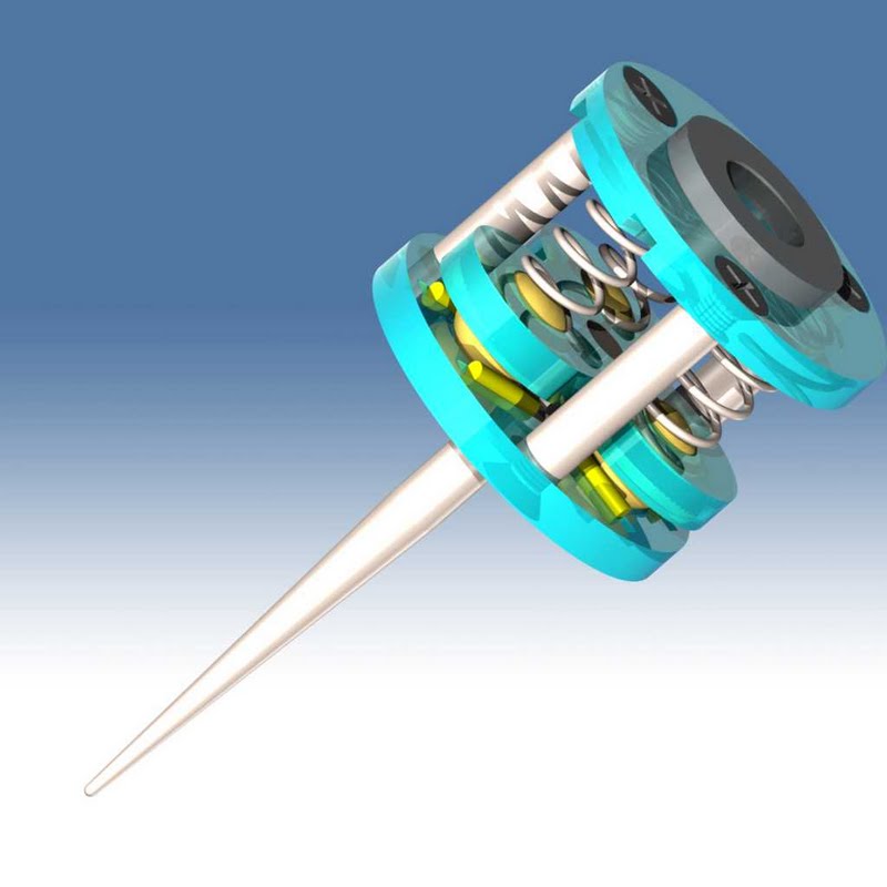
I am late to the party....but if anybody is interested in the machining files for this design I can post it. Works pretty well.
 Box Joint and Dovetail CAM software here: WWW.TAILMAKER.NET
-
02-01-2014, 04:47 AM #39
Member
- Join Date
- Sep 2006
- Posts
- 6463
Hi, better late than never.......pull up a chair, the beer's still cold enough to drink.......LOL.
I see the model you posted is, I would have to say "the Renishaw patent type", but I haven't actually seen the workings of one so it's just a lot of pinpoints coming together and forming a picture.
One picture is worth a million and a half words, and with that 3D picture it speaks volumes.
Going back to the 2004 posts I downloaded the zip file by Graham S and now it all becomes as clear as etc.
Like I said, why re-invent the wheel.....well with feverish brain activity, once I get the bit between my teeth it either has to be totally impractical or the too hard basket material.
At the moment, with the design I'm working on, the shaft carrying the probe tip, instead of being spring centralised could have 3 sets of ND magnets holding it central.......that makes it totally fixed but flexible to a degree that is impossible with springs.
I still have to work out the configuration of the magnets to get them to apply a force to a central point, but it has distinct possibilities.
The probe only has to move .02mm and the magnets will allow it to move slightly but always hold it firmly, and they can be adjusted for sensitivity by increasing the distance between them and V/V etc.
I think a small probe tip can be made for the round type using the ball from a ball point pen, and some of them have tungsten carbide balls, probably about .3mm diam.
On the subject of the contact zone, having a shaft end with a tapered point in a thin hole plate makes it infinitely adjustable to get the contact clearance to .02mm all around.
Now if I could get a very small laser pointer module with a point as small as .02mm that would be something else to work on.
I think a laser in a DVD player has something like that.
It would be targeted to a thin plate with a .02mm hole in it and a sensor behind the plate, and when on the hole it be visible, but a shift of .02mm to the plate would shut it off from the sensor, or something like that....very simple parts to get hold of and work with.
As far as the work piece is concerned it would need to be decided if all areas can be probed including those with undercuts, so it would need either flat scanning or rotating with a 4th axis, you can't have both.
Specifically this design is for a 3D digitising probe of objects with profiles above a flat plane, but it could also be used to do edge detecting etc.
Ian.
-
02-01-2014, 07:28 AM #40
Registered
- Join Date
- Aug 2011
- Posts
- 999
The magnet idea sounds interesting. But you must take the non-linearity of these magnets into account. With a small air gap the forces of rare earth magnets are very large (probably too much for mechanical scanning) and they fall off rapidly when the gap opens.
In the meantime I found some older videos I took with that touch probe gadget. It was a fun design and fabricating exercise but I must admit I have not used it for a long time.
Now where is that beer?
Scanning a highly curved and uneven surface and projecting/warping a Vcarve Pro output file onto that surface:
 Box Joint and Dovetail CAM software here: WWW.TAILMAKER.NET

 Reply With Quote
Similar Threads
-
Another Touch Probe
By JerryBurks in forum DIY CNC Router Table MachinesReplies: 19Last Post: 12-02-2021, 09:07 PM -
NO Touch Plate and NC Touch Probe switch inversion using an Arduino UNO
By Kenny Duval in forum Benchtop MachinesReplies: 12Last Post: 06-05-2013, 06:05 PM -
how to center a homemade touch probe
By isowe in forum Digitizing and Laser DigitizingReplies: 1Last Post: 05-16-2012, 02:23 PM -
How to do protected moves for homemade probe?
By pbarratt in forum Mach MillReplies: 0Last Post: 10-24-2010, 12:39 AM -
touch probe
By basswakr in forum CNC Machine Related ElectronicsReplies: 0Last Post: 08-14-2010, 02:18 PM
