There are at least two candidate there.
Here is one I bought to run a different motor.
http://www.surpluscenter.com/item.as...tname=electric
Here is another.
http://www.surpluscenter.com/item.as...tname=electric
The motor I bought but have yet to use is here.
http://cgi.ebay.com/Diamond-Back-Tre...QQcmdZViewItem
It is a nice motor and has a big fan on it already. Some of those at Surplus center need the fan bought extra.
Thread: Mill project
Results 21 to 40 of 52
-
11-19-2007, 01:10 AM #21
 Gold Member
- Join Date
- Jun 2004
- Posts
- 6618
Lee
-
11-20-2007, 02:16 AM #22
Registered

- Join Date
- Nov 2007
- Posts
- 479
Wow, looks like a nice "Rigid" machine you got there.
-
01-06-2008, 03:18 PM #23
Registered
- Join Date
- Feb 2006
- Posts
- 1187
Hey Jester any update? I was taking another look at your machine and was thinking man that looks like a prime candidate for a polymer concrete base. Keep us posted!!!
-
01-06-2008, 11:57 PM #24
Gold Member
- Join Date
- May 2003
- Posts
- 792
Did someone say polymer concrete?

-
01-14-2008, 11:10 PM #25
Registered
- Join Date
- Jul 2006
- Posts
- 23
Sorry, no updates yet.
I will look into polymer concrete some more, it may be the perfect solution for my base and I hadn't even thought about it. Thanks!
-
10-01-2008, 04:35 PM #26
Gold Member
- Join Date
- Sep 2006
- Posts
- 1738
Whatever happened with this, looking into building a mill one day and looking at all designs!
Updates please!!!!!
-Jason
-
10-01-2008, 07:25 PM #27
Registered
- Join Date
- Feb 2006
- Posts
- 1187
Yeah whats up Jester? This was one of my fav designs and would love to see the end result!!!!!!!!!!!
-
11-06-2008, 12:18 PM #28
Registered


- Join Date
- Mar 2005
- Posts
- 305
great pic, are you test run? Originally Posted by Jester966

-
11-10-2008, 05:56 AM #29
Registered
- Join Date
- Nov 2007
- Posts
- 118
Hi tivoidethuong.
Very nicework. Alot of man hours.
So what are you thinking about using for a motor? Treadmill?
Belt drive or gear?
-
11-11-2008, 09:25 AM #30
Registered
- Join Date
- Dec 2006
- Posts
- 839
WHat ever you do , don tlet it set there until it starts rusting.
The PC would make a great base, or even one of those cheap Chinia Granite surface plates. That would make a great base and easy/quick to make happen. It could even be easy to change out latter if you did build a different base later. Plus there already pretty darn flat, even the cheap ones. Drill it and put inserts in it to bolt the mill parts down to.
I seen a high dollar factory built setup ( assembly machine that did only one thing,was about &200,000.00) that came with a high quality granite plate for the base of the machine. It had rails & blocks just like yours bolted down on it and then the whole thing was set down in a inclosure. It was intended to be very acurate and the granite block was used because of no changing in size through different temps. This thing had to operate in some tight tolerances and theh granite base is part of what helped it hold them.
I will one day build a setup much like yours and use the granite block base setup. I believe you can get a 24' X 36" for around $150.00 at Grizzly. This one would weight about 400lbs so it would be a very sturdy setup. Plus for $79.00 you can even get a stand for it, but I dont know how sturdy the stands are.
If I was going to use one I dont know about bolting the column down to it, although I have seen things bolted like this that gave no problem. But my thoughts was to bolt a 1" steel plate down to the granite and then bolt down to the steel plate. This would allow for grinding flat if need be plus be alittle stronger hold on the column part.
Jess
-
01-18-2009, 02:06 AM #31
Registered
- Join Date
- Jan 2009
- Posts
- 82
Wow! think we all want an update on this one.
-
01-18-2009, 03:31 AM #32
Registered
- Join Date
- Jan 2009
- Posts
- 82
What size steeper motors would be good on this? Originally Posted by Jester966
-
01-18-2009, 02:03 PM #33
Gold Member
- Join Date
- Jun 2004
- Posts
- 6618
Looking great!
I would say that it depends on your screws and if you are going to use timing belts, but I used Keling 495's on my mill. I run them direct drive on X and Y, but I had to use a belt on Z. I can rapid @ 300 IPM with no issues, but I don't run it that fast. I use about 200 IPM on Z and maybe 240 on X and Y.
I am also using Gecko 203V's and a Keling 72 VDC 12 A power supply.
This size or larger should satisfy your needs fine I think.
I think you may need a smaller vehicle so you can have ongoing projects and still park inside. You full size vehicle is keeping us from seeing this things do it's thing. Lee
Lee
-
06-20-2009, 04:32 AM #34
Registered
- Join Date
- Jul 2006
- Posts
- 23
 progress...
Well due to a series of job changes, a lack of funds, a move to a house with no garage (
 ), and the fact that I no longer have access to the shop in which I started this build, it has been a long time since I have been able to work on this project. However, I have finally had a chance to make a small amount of progress!
It's not much, but I've now got an ACME lead screw installed for the Y-axis. Eventually I would still like to convert the machine CNC, but since I'm too broke to buy ballscrews and servos, for now I am working on installing ACME screws to get it working manually.
The screw, nut, bearings, and handle were pulled from an old piece of equipment that I got from work for free. To install the screw, all I had to make was a new block to hold the nut, and the front plate to screw the front bearing "block" to. I also had to drill/counterbore four new holes in the saddle plate in order to move the nut foreward because my original design had the nut positioned in the center, and this screw is already a bit too short. Because the screw is too short, I have had to sacrifice about 2" of travel on my Y axis. I still have 8" of travel though, and I think that will be plenty until I (eventually) replace it with a longer screw.
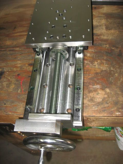
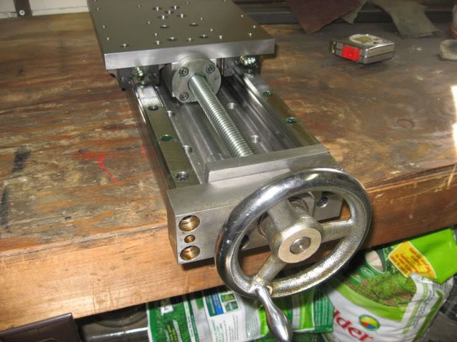
The huge block on the front (which houses the bearings) looks very crude. This was also pulled from the equipment and, because I was working with only basic tools available, it was much easier to use it as-is. I will eventually come back to this and tidy it up with a new plate that houses the bearings itself, rather than just bolting a bearing "block" to the plate. For now though, it gets my Y-axis moving and allows me to move on to the next step.
Currently there is no indication of measurment along the Y-axis. I think this is a minor problem though because there are other ways to make accurate movements for finish cuts, like using indicators. Regardless, I will address this after the major components of the machine are finished. Since I will later replace all the hand wheels with my own (matching) wheels anyway, I will make dials at the same time. Eventually I would also like to install scales and a DRO anyway.
Here's a better picture of the whole (what's done so far) table:
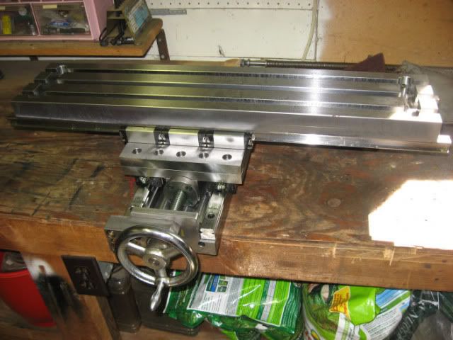
On the bench just behind the table you can see a 3/4"-8 ACME screw that is a spare lead screw for an Atlas 10"x36" lathe. This is what I am planning on using for the X-axis (because, like the Y-axis screw, it is also free!).
Although it is only a small step, getting the Y-axis working is very motivating. I now have some limited access to the manual machines at work, so when I can find time I will work on the parts to get the X-axis functional.
-
06-22-2009, 09:29 PM #35
Registered
- Join Date
- May 2005
- Posts
- 89
Wow! Its nice to have you back!
-
10-10-2009, 01:20 AM #36
Gold Member
- Join Date
- Sep 2006
- Posts
- 1738
Man, Can you imahine this machine with ballscrews, CNC'd and a really nice heavy steel base plate to attach eveything? You would be set!
Wish there were updates, I hope to use this design one day.
-Jason
-
01-26-2010, 08:29 AM #37
Registered
- Join Date
- Jul 2006
- Posts
- 23
Quick update:
Due to a position change at work, I've now got access to manual mills and lathes (and a surface grinder) again. So this week I'm working on getting the X-Axis working. I'm still using acme screws, but it will be relatively easy to swap them out for ballscrews in the future when I get into the CNC conversion.
-
01-26-2010, 05:08 PM #38
Gold Member
- Join Date
- Sep 2006
- Posts
- 1738
Omg yes! Been waiting for this!!!!!
-
02-12-2010, 06:16 AM #39
Registered
- Join Date
- Jul 2008
- Posts
- 922
hope you got your essentials sorted m8

-
02-12-2010, 05:09 PM #40
Registered
- Join Date
- Feb 2007
- Posts
- 24
Hello,
I like the style of your machine. Which kind of axiscovers are you planning?
Greetings,
Rene

 Reply With Quote