


Before I set some questions, here is the file I will talk about: https://longgo.eu/cnc/cone-loft.sldprt
It is made on SW2015. Also, need to point that is just for my learning curve. Nothing to be manufactured as serial parts. Just for education.
Material for the part is normal 2mm steel. Just for start and test I use K-factor of 0.5
The bending will be made in real test with air bend, and tool is R1 mm. All that are things we have in the company.
What is my issue? The sum of all bend angles per side are not equal to 90°..
My first try was with simple 180° arc. By that I mean sheet arc with radius 55mm divided on 10 equal segments. Roughly that should be about 18° per bend.
When Solidworks produce unfold, it come up with 15,1° and when tested on real 2mm steel it was waayy off the target.
Here, in that file as you see all summed angles for each side are 71.68° and if I subtract it from 90° it leave me with 18.32° remain.
If that is tested with bending machine with 2mm steel plate will produce wrong bend.
From other hand, If I divide that 18.32 on 8 bends that leave me with 2.29° per bend. So, if test once again but add that 2° per each bend, it actually come quite close to the real 90°...
Yes, I try with different K-factors from 0,25 up to 0,48. Also try with calculated Bend Allowance same results.. Also when found some ready excel table with data prepared in it, I select it in SW and the unfold end up with same angles..
Obviously there is something very wrong in my way of doing the things, but what it is?
There are tons of videos how you make loft, how you just unfold the part but didn`t manage yet to find right help tutorial to find my mistake.
If someone have the good will to pass me some tips, or link to good guide will be great!
Thank you
Results 1 to 6 of 6
-
01-15-2024, 10:59 AM #1
 Member
- Join Date
- Mar 2007
- Posts
- 13
 Issue with solidworks sheet bent / unfold - constant wrong angles
-
01-15-2024, 09:48 PM #2
Flies Fast
- Join Date
- Dec 2008
- Posts
- 3109
Re: Issue with solidworks sheet bent / unfold - constant wrong angles
Forgive my ignorance...
Should your folded model be drawn true and correct.... then unfolded using a k-factor
Seems as if you are trying to use SW as the bending machine, instead of designing, then unfolding for the flatpack pattern.
Usually the press has the folding software
-
01-18-2024, 09:41 AM #3
Member
- Join Date
- Mar 2007
- Posts
- 13
Re: Issue with solidworks sheet bent / unfold - constant wrong angles
Yes, model been drawn with all correct dimensions on it just as 3D model. Not starting as flat surface and then build some sides via sheet metal options..
After my model been created the unfold method was used where I select the bend to be done by 8 facets, K-factor and so on..www.longgo.eu
-
01-19-2024, 01:24 AM #4
Flies Fast
- Join Date
- Dec 2008
- Posts
- 3109
Possible maths error ??? Originally Posted by longgo

... you may have issues regarding # of bends verses # of segments.... 10 segments = 11 bends, or if you want 18° bends for a 180° return, which is 10 bends or 9 segments (10th segment is the total bend result)
Eg...think about 45° bends, 4 bends/ 3 segments for 180° total bend...
All this is theoretical, each machine would need over-compensation to achieve correct size. It depends on material properties, springback, bend length, design requirements, machine capability.. it is not all easy, a lot depends on operator knowledge.
-
01-20-2024, 05:16 PM #5
Member
- Join Date
- Mar 2007
- Posts
- 13
Re: Issue with solidworks sheet bent / unfold - constant wrong angles
Thank you for taking part in that matter! And sure, can be calculation error..
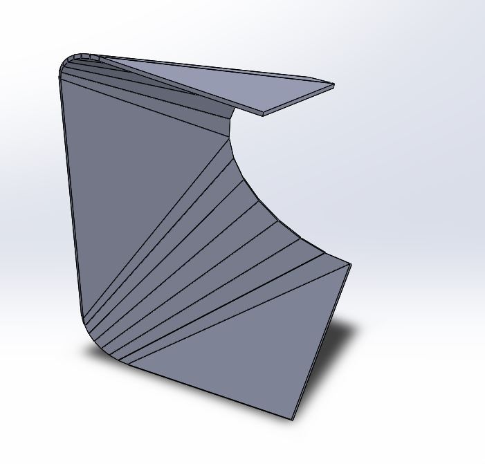
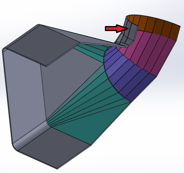
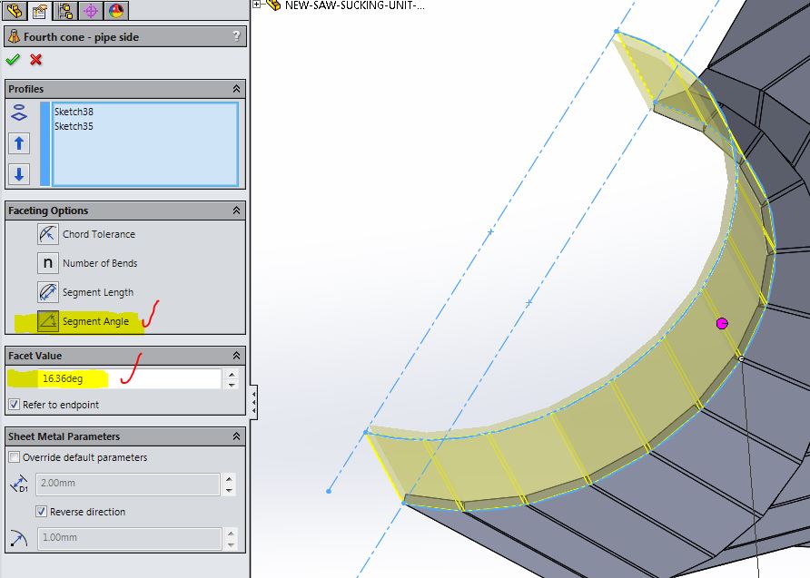
My logic is as follow - if I have 180° arc(semi circle) and divide that on 12 segments. Then it should give me 11 bends. For the purposes of this post there are new pictures attached.
The part is on the first one, and it show with segment of it I wish to unfold.
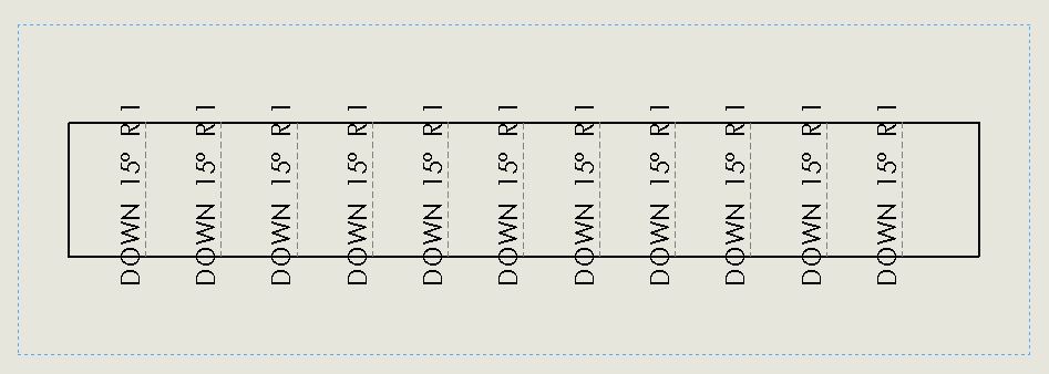
On the second, you can see that I point just number of segments as 12 and sure enough Solid Works produce 11 bends and 12 segments. But when I unfold that part, I get 15 deg/bend. And in fact should be roughly 180/11 = 16.36°
If change the tactic and instead segments , I point angle per bend and put 16.36° as value it once again produce 12 segments and 11 bends but unfolded show 15° per bend.. (same as on the picture)
Changing K-factor from 0.2 via 0.5 to 0.8 does not affect that angles at all..
As for the machine, material, bending tools and etc.. I agree fully! But not there yet.
Can it be also, that it is add some extra degree at both ends?
If I have 180° semi circle, I assume that both arc end of the part lie in same virtual straight line.
But what, if the start and end are also calculated as 1/2 bend?
Once again: 180 / 12 segments = 11 bends * 15° Then on both ends we have 7.5°/side => 2*7.5 = 15°+(11*15°) ....
If I may return back to the file from the first post. It will be easy that you could you download it, then try how it will unfold with your options and ideas set up.
After it been done, put in Drawing sheet file, unfold to 1:1 scale and I can see how it will show as degrees there. And I can repeat in my version and see what actually going one..www.longgo.eu
-
01-20-2024, 09:25 PM #6
Flies Fast
- Join Date
- Dec 2008
- Posts
- 3109
SSS 6sstss? 6th s
You cannot have more segments than bends Originally Posted by longgo
1 bend gives 0 segments
4 bends give 3 segments
12 bends give 11 segments, the lengths before and after the area of bend are not segments
The number of bends is what is divided into total sweep angle.
Ps. . There have been no attachments on your posts
K factor is only used to calculate the amount of material in the bend WHEN unfolding, it is related to the material properties and how it performs when 1 side is stretched & the other compressed. ....
For learning, leave it as 50% (or 0.5) which is along the middle of your material ( be aware that some materials stretch easier than being compressed)
-
01-21-2024, 01:24 AM #7
Member
- Join Date
- Mar 2007
- Posts
- 13
 Hm.. that seem to be confusing me. (unfortunately not the first time in my life..) Originally Posted by Superman
So far my understanding was like that :
- K-factor lets say 0.5
- material thickness let`s say: 1 mm
- sheet length - 100 mm
if bend it on 90° in the middle with R1 tool I will end up with two segments of 49.5mm and one bend of 90°..
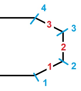
Now think I see where probably was my mistake all the time! Originally Posted by Superman
I hope this time finally got it: segments (in red) , and bends (blue) Originally Posted by Superman
Maybe in 180° arc divided in facets , the program "consider" the bending segments start differently from what I think is right and actually ignoring one give exactly what I have seen...
Now is a bit more clear. Thank you!!
I was thinking the same, that for learning purposes and 2mm steel sheet, K=0.5 or 0.48 should be fine.. Originally Posted by Superman
The link was in the first post, but here again the file: https://longgo.eu/cnc/cone-loft.sldprt
Maybe if I had attached it as ZIP should of been better. Sorry for the misleading ! Still , if you have will to take a look at it and give me some last thoughts will be really great.
Highly appreciate your spent time to give me that information so far.www.longgo.eu
-
01-21-2024, 02:01 AM #8
Flies Fast
- Join Date
- Dec 2008
- Posts
- 3109
Re: Issue with solidworks sheet bent / unfold - constant wrong angles
I'm currently on leave, so no access to CAD.
I know it can be confusing, but I started doing manual unfolding using CAD.
IE... R1 on internal bends, 4mm plate (external bends=R5), (K-factor of 0.5 [middle of sweep arc]) means your bend sweep is on a R3 radius, you calculate the sweep arc distance on this R3, and this is the modified "gap" that is used for your flat design, and the press, the Y distance is gauged to the middle of this "gap".
Now... say R1 rads on 1mm sheet, K-factor on 0.5 means you calculate rads of R1.5 (R1+ 50% of sheet)
So for a 90° bend... Circ = pi X Rad / 4 = 1.1780972451 for the "gap"
-
01-21-2024, 02:54 AM #9
Community Moderator
- Join Date
- Apr 2018
- Posts
- 134
Re: SSS 6sstss? 6th s
longgo did upload attachments, as they are viewable at IndustryArena here: https://en.industryarena.com/forum/s...96#post2576596 Originally Posted by Superman
... but those images are not viewable at CNCZone due to problems with the stone age server systems.")
These images belong to post #1
-
01-21-2024, 03:12 AM #10
Community Moderator
- Join Date
- Apr 2018
- Posts
- 134
Re: Issue with solidworks sheet bent / unfold - constant wrong angles
These belong to post #5:

-
01-21-2024, 03:17 AM #11
Community Moderator
- Join Date
- Apr 2018
- Posts
- 134
Re: SSS 6sstss? 6th s
This one belongs to post #7:
I don't have any control over server issues, and can offer no solution except to post images to a 3rd party host and link them here. I have earlier alerted Admin to similar problems, but their approach is to just use Band-Aids and the problem continues . . .
-
01-21-2024, 05:41 AM #12
Flies Fast
- Join Date
- Dec 2008
- Posts
- 3109
Thanks Rader for reposting the images, makes a big difference. I dont think I will ever switch to Arena, I'm that close to putting my feet up, old habits die hard and stubborn as hell, and i dislike their layout, bloody horrible. Originally Posted by RaderSidetrack
Got the 'zone setup nice, no ads, good rep, I ain't gonna change.
As for Longgo, the pics open up a different story... lobsterbacks, and transitions etc.
We use this bend software for sheetwork design etc.
It can output DXF (for machine cutting of flatpack) and allows 1:1 prints for manual bends on a brakepress (no need for gap calcs & so on. Just bend along a line to the approx. angle, .... it is what it is ...
https://cad.com.au/software/plate-n-sheet/
-
01-21-2024, 03:04 PM #13
Member
- Join Date
- Mar 2007
- Posts
- 13
Re: Issue with solidworks sheet bent / unfold - constant wrong angles
Damn! I start as user of the old forum and after they been "transfer" here to the Arena just start to use it.
Didn`t know that all my posted images are not visible!
If I did, then should of put them on my host or mega.nz or similar.. Assumed that all see them as I see it here in my posts....
As for the software - thanks! But for sure I wish to stuck to Solidworks because I use it as design and CAM tool for other projects and somehow wished to add that sheet (or sh*t) work to itwww.longgo.eu

 Reply With Quote
