


Hi all,
I´m planning to develope and make a cnc router and I have questions to some design topics.
The concept I have has quit a big Z travel (>500mm) what makes it hard to get the mashine stiff enough on a conventional router design (X+Y and torsional for the Z axis). The space for the mashine is limited (router shall be used as a table if not in use and also storage room under the table is required). Router shall mainly be used for alu, wood and foam but I sure want to get it as rigid and accurate as possible. Working area as big as possible and in Z min 500mm.
So I´m trying to solve this issue with a different Z travel concept. The Z travel is moved away from the gantry beam so that I can control the forces better. To reduce the issue with the additional weight the plan is to use pneumatic cylinders to compensate the weight in Z and strong enough AC servos to handle the aditional forces in X.
There are also 4 linear rails for the X and Z axis and 2 rails for the Y axis. This will make the alignment of the axis quit tricky and hard work... but I am hoping solve that issue and so get the forces better under control(more connection points and distances between them to reduce the forces).
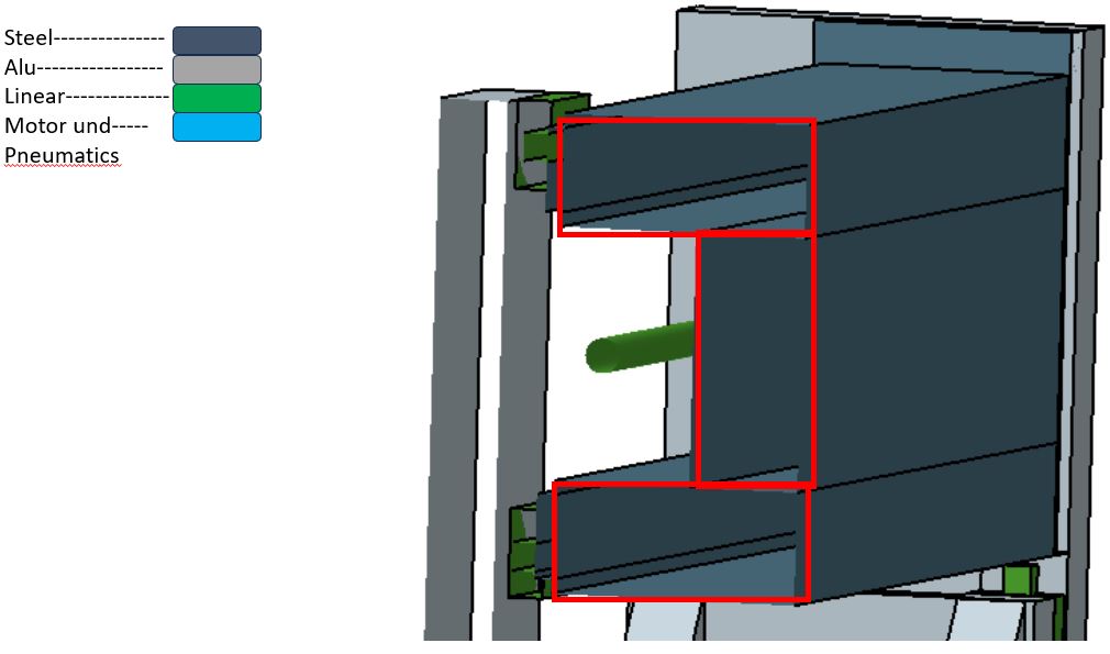
The plan is to use filled (damping) steel tubes, WIG/TIG to weld them together and the Alu will all be made out of a huge 50mm thick Alu sheet (I have it so I try to integrate it into my concept to save some costs). To get some more stability and weight onto the table I planned to make a UHPC bed (only the alu working plate will be fixed to it).
Alot of blabla so I made a quick and dirty concept of what I´m thinking about: see the attached screens (it´s really a rough first sketch!).
Questions:
1. Does the concept with the Z travel and pneumatic cylinder make sense?
2. Is the aproach of reducing forces with the con of having to align more rails worth a try?
3. The weight and forces on the X axis are high in motion. Do you think I can handle that from a mechanical
standpoint (make table/bed heavier)?
Please throw your darts and thought´s to this concept, it´s my first mashine and I appreciate (and need) input.
Thanks!
Sebastian
Results 1 to 11 of 11
-
02-14-2024, 05:04 AM #1
 Member
- Join Date
- Feb 2024
- Posts
- 0
 CNC Router - concept to allow a big Z travel
-
02-14-2024, 11:05 AM #2
Member
- Join Date
- Dec 2003
- Posts
- 1227
Re: CNC Router - concept to allow a huge
No image showing.We occasionally get posts from somebody wanting to build a machine with a huge Z travel and I normally make the point that it does not mean that you will be able to cut absolutely any shape that is less tall than the Z travel.I recommend that you create a model of your proposed spindle and then consider how much of a limitation it will be to have the Z axis backplate and the spindle body extending beyond the diameter of the tool.
Attachment 501702
-
02-14-2024, 02:37 PM #3
Community Moderator
- Join Date
- Apr 2018
- Posts
- 134
Re: CNC Router - concept to allow a huge
NordCore did post images, but due to server issues they are not showing at CNCZone. See this sister site Industry Arena thread: https://en.industryarena.com/forum/s...34#post2578934
I have copied the photos from IA and posted 6 here, and the others in posts # and #7 below.
-
02-14-2024, 09:56 PM #4
 Member
- Join Date
- Apr 2004
- Posts
- 5737
Re: CNC Router - concept to allow a huge
Points given for innovation here, but I don't see this working too well. By lifting the whole gantry beam for each Z move, while the spindle is fixed in position, you lose the ability to descend into a cut any deeper than the tool stick-out plus the spindle nose allows. The clearance under the beam becomes a critical limiting factor. Say you're trying to carve something that looks like Mt. Everest. Cutting the peak would work okay, but as you descend down the slope, if the tool can't reach (and there's a limit to how long they can be, especially when cutting materials as hard as aluminum) the beam is going to bang into the summit as it tries to pass it. On a normal router, the spindle would be able to descend the slope to the limit of the Z travel, but on this one, most of that travel is useless.
-
02-14-2024, 10:35 PM #5
Member
- Join Date
- Jul 2018
- Posts
- 6341
Re: CNC Router - concept to allow a huge
Hi Nord - Can't see your images or the links. use the go advanced feature and imbed files please. Now if I get your drift correctly you want to use twin rails on the axes. This does not work. Only one rail is needed. This is because square rails resists moments so the first rail in the load path does all the work. The next rail does not see much at all. If you have simulation or FEA you can prove this pretty quick. I have modelled it several times to come to this conclusion. Better off using bigger rails/cars to improve stiffness or better spacing to improve geometry.
The 500mm Z needs to be considered carefully. You need extra long tools to take advantage of the length and depending on the part geometry it can backfire on you with side clearances. Plus the 500mm needs to be really really stiff and if the 500 is only used once or twice a year you have a poor machine for 99% of the year. I'd look at a 5 axis machine if this is really what you need then you can tilt the head to overcome the issues. Peter
-
02-14-2024, 11:15 PM #6
Community Moderator
- Join Date
- Apr 2018
- Posts
- 134
Re: CNC Router - concept to allow a huge
I revised my post #3 above to directly have 6 images attached. One more image is here, and the last is in post #7:
-
02-14-2024, 11:20 PM #7
Community Moderator
- Join Date
- Apr 2018
- Posts
- 134
Re: CNC Router - concept to allow a huge
Last one:
The problem with images not being consistently visible is very frustrating. And Moderators are subject to the same problems as everyone else -- the servers are a recurring problem.
My personal recommendation to eliminate all the image problems is to post images to a 3rd party photo host, then post links to those images here. Hosts include Flickr, Imgur, etc. A free host that I like and use is: https://postimages.org/
-
02-14-2024, 11:20 PM #8
Member
- Join Date
- Jul 2018
- Posts
- 6341
Re: CNC Router - concept to allow a huge
Hi Nord - A lifting gantry design. Think it through - if you have 500mm z and you have a 450mm high billet, how does the gantry get down to the bottom of the bowl? So you still have a 500mm Z cantilever? and a 450mm long tool. I once saw a 400mm tool in a machine get out of balance and bend and fly across the room., Very dangerous!! Peter
if you need 500mm because the part is 500mm high but your only doing 100mm deep cuts or less to it then consider a pit vs a lifting gantry. Peter
-
02-15-2024, 05:54 AM #9
Member
- Join Date
- Feb 2024
- Posts
- 0
Re: CNC Router - concept to allow a huge
Hi routalot, yes the detailed CAD will be made. At this point I´m trying to settle the rough concept bevor I start creating the parts for FEM and calculations. At this point I dont even know how the gantry will be shaped and so on. Originally Posted by routalot

Thanks!
Sebastian
-
02-15-2024, 06:07 AM #10
Member
- Join Date
- Feb 2024
- Posts
- 0
Re: CNC Router - concept to allow a huge
Hi RaderSidetrack, thank´s for your support! and clarification. I have some issues using image hosters but i will find a workaround for that issue. Originally Posted by RaderSidetrack
-
02-15-2024, 06:13 AM #11
Member
- Join Date
- Jul 2018
- Posts
- 6341
Re: CNC Router - concept to allow a big Z travel
Hi Nord - Do not use image hosters. Use the "go advanced" feature at the bottom of the thread box. If you use a host the links will fail at some time as they time out. Then the thread will not be able to see the images. If you embedded them in the thread they are here for as long as the forum is supported... Peter
-
02-15-2024, 06:37 AM #12
Member
- Join Date
- Jul 2018
- Posts
- 6341
Re: CNC Router - concept to allow a big Z travel
Hi Sebastion - Now I have seen your images I'll answer your Q's:
1) In a word no. It will make the machine very costly for the purpose (which you need to explain better then "I want 500mm z") it has redundant rails and cars and a complex gantry to keep square and level. Due to ballscrews being slightly different they do wander over time due to this in-tolerance. This will take your gantry out of level over time.
2) again in a word , Not worth a try. Since square rails oppose moments, having extra rails does not help. The first rail in the loadpath does most of the work. Very large machines (like size of houses machines) have double rails but this is so they can be assembled with stability not to improve or decrease the loadings
3) A machine can always be made "strong" enough to do the job. The actual forces on cnc machines such as this are quite small. Even small carriages can support tonnes of weight... Machine rigidity & simplicity are the things to chase and that will give the machine its required strength.
So its your first machine, good on you for trying . Firstly a good machine is made to a fulfil a purpose. If you try to design a general purpose machine the compromises are too big and you go round in circles and eventually end up with a machine that's crap (I've been there) or a machine that looks like the usual machines. The usual machines have been refined over a long time say the last 100 years to get where they are. They are deceptively simple, so simple, you say I can do better eg use twin rails for a design vs a single rail. So A) define what you want the machine to do as this will answer many of your Q's & give you a direction that will arise often in the design journey B) find a commercial muse machine that does what you want and contemplate why it is what it is. It will inform you of many things that will reduce your thinking stress and project time span...
Regarding a mixed media build. I recommend you stay in one material universe. Mixing materials may get you into trouble with thermal expansion differences. eg steel expands 13um per degree vs aluminium at 27um and concrete about 13um...These sound small but they do make a difference in a machine and commercial machine builders go to long lengths for thermal stability and so should you. I'd forget about filling steel tubes with stuff, commercial machines do not do this and this forum has 1000's of discussions about this topic. My view is use a thicker tube, its then stiffer and easier to do things to in future and far cheaper... and banging parts with hammers and listening to the ring or soft ring does not really answer the question about the machines dynamic stiffness, its far more complex than that... Peter
-
02-15-2024, 08:01 AM #13
Member
- Join Date
- Feb 2024
- Posts
- 0
Re: CNC Router - concept to allow a huge
Hi Andrew, thnx.. yes the limiting factor for pocket´s / slopes is the gantry (issue with spindle and backplate is the same as in conventional concepts). In my use case (I´m targeting for 220mm) ther is no need for that and if I ever come in the situation that I want to handle that task I can attach a second adapter plate in the lengh / shape i need. Originally Posted by awerby
I am planing to carv foam to shapes that are possible with this setup.
The hight is needed for the "big" foam block´s that are going to be mashined from both sides but mainly it is going to be working under "normal" conditions. I am hoping to get around the confliction requirements with this concept. This mashine build is for hobbie use cases but I want to do the best I can.
Thanks!
Sebastian
-
02-15-2024, 09:47 AM #14
Member
- Join Date
- Jul 2018
- Posts
- 6341
Re: CNC Router - concept to allow a big Z travel
Hi Sabastian - Since your going to mainly cut foam I suggest you use a conventional long z axis, not the lifting gantry. I suggest that you design the spindle so it can be canted 45deg or even to horizontal. This means you can machine the left hand side with the tool leaned, this overcomes the collision angle issue. Then you manually cant to the other side and machine the right hand side. I did this on my first machine and it worked very well... You should consider a rotary platter and then you have a very good solution for this sort of task. The platter can be simply manually registered to four quadrants or can be under rotary axis control.. Peter
-
02-15-2024, 01:43 PM #15
Community Moderator
- Join Date
- Apr 2018
- Posts
- 134
Re: CNC Router - concept to allow a big Z travel
Originally Posted by peteeng
While I understand peteeng's concerns about images being available only as long as a 3rd party host cooperates, in this case there are other factors as well. CNCZone and Industry Arena are sister sites, and thread + images are [allegedly] automatically replicated between both sites. HOWEVER, the replication process is not reliable, and sometimes that failure includes failure of images posted to Industry Area to replicate to CNCZone.
If you want to avoid using a 3rd party host, my suggestion is to post threads (including images) to CNCZone (don't post to Industry Arena). But sometimes posting images directly to CNCZone also has problems. For instance, in this thread I have images in three different messages. That is because the server would not cooperate in accepting all 8 images in one message even though 8 attachments is within the maximum limit.
To minimize frustration with uploading multiple images to a single post, only to have the upload fail, use multiple messages to attach multiple images instead of trying to cram 8 images into one message. (The server says 8 attachments is the limit, but 8 does not consistently work.) So I'd say limit attachments to no more than 4 per message. And if you have any difficulty with uploading the 2nd, or 3rd or 4th -- move on and create a new message to hold the additional attachment instead. And remember -- use CNCZone and not Industry Arena.
-
02-16-2024, 04:57 AM #16
Member
- Join Date
- Feb 2024
- Posts
- 0
Re: CNC Router - concept to allow a big Z travel
Hi Peter, Thank you for all your great technical input! The point is that I was trying to combine conflicting directions for the mashine build but you are right. I will now slice the foam and glue them after mashining so I dont need that big Z travel. With all this input I have the direction I was looking for (even more clear than I was hoping to get Originally Posted by peteeng
)
Thank you Peter!
Sebastian
-
02-16-2024, 06:11 AM #17
Member
- Join Date
- Feb 2024
- Posts
- 0
Re: CNC Router - concept to allow a big Z travel
Hi Peter, yes I am going with a long Z axis now (something like 250mm / 300mm if i find a way that I feel comfortable with it). And again great input with the rotary platter, have to do a deep dive but I like it (gives me more possibilities in the foam than I was thinking about). I´m now going to make different design´s (gantry, vertical gantry support and z axis all steel and UHPC) hoping my specs are duable now. Run FEM to confirm what is the best direction for me to go. Originally Posted by peteeng
I will post the different concepts here bevor I´ll go to the FEM simulation (static).
Thanks Peter!
Sebastian
-
02-16-2024, 06:28 AM #18
Member
- Join Date
- Feb 2024
- Posts
- 0
Re: CNC Router - concept to allow a big Z travel
Hi RaderSidetrack, I will follow your advice. Maby a good point for the FAQ to minimize your frustration (that was where I first looked after I noticed the issue).. just trying to help Originally Posted by RaderSidetrack
Thanks again for your great support!
Sebastian
-
02-16-2024, 07:11 AM #19
Member
- Join Date
- Jul 2018
- Posts
- 6341
Re: CNC Router - concept to allow a big Z travel
Hi Sebastion - My standard Z axis is 350mm. The z axis plate is made from two pieces of steel 3mm thick bent into a channel and mounted back to back. They are about 180mm wide and the flange is 50mm deep . It cuts aluminium easily. I'd expect something similar would go to 500mm and deal with timber and foam easily. The z axis is actually easy to get right, its the saddle that will take a lot of your time. Keep at it. I've attached images one of my routers called Franky for your info. Peter
re: images I have always posted in cnczone for years and I hasn't given me any issues. Theres been lots of issues with Ind Arena twinning images into cnczone.
This is the sort of machine you should consider - but have a rotary platter on the bed. Either permanent or removable.
https://www.stylecnc.com/cnc-wood-ro...25-4-axis.html
-
02-17-2024, 01:20 AM #20
Member
- Join Date
- Jul 2018
- Posts
- 6341
Re: CNC Router - concept to allow a big Z travel
Hi Sebastian - Now you have a direction with the machine I also suggest you don't worry about a gantry. That's because with a platter you can get to all sides with the rotary so half the gantry motion (and footprint) is wasted. This means the machine is simpler as you use 3 axis vs 3+1 axis (plus the tilt and the rotary of course). Look at these two Mori's for instance. If you use the tilting spindle these would be simpler to build then a gantry machine. This then becomes a very versatile 5 axis machine. Peter
as a side note - your original issue was trying to better arrange the machine to decrease the forces on the bearings / machine. These two configurations are called moving column machines. They solve the issue you describe as the tool forces are always (nearly) within the footprint of the bearings. With a gantry the spindle is offset forward of the gantry so side loads can never be within the bearing footprint so it will always have a secondary torsional component in the cut and machine. The two machines attached solve this issue neatly and only have the primary loads to deal with. Peter

 Reply With Quote
