


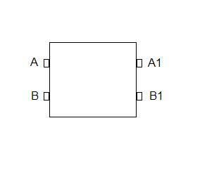
Hi Joe, I do apologise if the following is trying to 'teach granny to suck eggs' The 4 pin pcb tactile switches have two sets of pins connected internally as in the diagram here. A is connected to A1 internally and the same is the case with B and B1: -Originally Posted by joegib

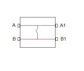
I have just edited this post and added a modified switch diagram which I pray shows the internal wiring of the switch and I hope helps to explain the concept of using it to produce a matrix keyboard, I do hope that i'm not insulting anyones intelligence :
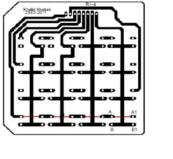
The internal connections create the horizontal rail in conjunction with the tracks on the pcb (below). An example is shown in red as if all the switches on that track were mounted. When the switch is pressed it connects the horizontal rail to the vertical through the A-B and A1-B1 connections. Hope this explains the pcb layouts published on this site.
Best regards
Terry
Thread: Rotary table indexer
Results 621 to 640 of 815
-
01-28-2013, 05:49 PM #621
 Registered
- Join Date
- Feb 2007
- Posts
- 33
-
01-28-2013, 08:34 PM #622
Registered
- Join Date
- Jan 2011
- Posts
- 0
Not working at 10 MHz
First of all let me thank Steve for great design. I also would like to thank everybody who posted to this topic.
My indexer does not start if crystal frequency is above 4 MHz. It just lit the first digit of LCD and freezes. At 4 MHz it works normally. PIC18F452, tested with 2.12 and 2.12c software.
What could be the reason for that?
Thanks!
Konstantin
-
01-28-2013, 08:42 PM #623
Registered
- Join Date
- May 2006
- Posts
- 184
Hi Konstantin,
check the layout around the crystal and associated caps - is there anything that could introduce extra capacitance? Make sure the joints are soldered properly for these components too.
Have you've tried different crystals? Have you tried replacing the two capacitors around the crystals? Finally a different 452?
Off the top of my head I would say it has to be one of those....
Cheers.
Steve.
Originally Posted by signus
-
01-28-2013, 08:47 PM #624
Registered
- Join Date
- Jan 2011
- Posts
- 0
Steve, yes I've tried with several crystals, the capacitors and connections also seems to be ok. Will try with another PIC. Can fuse bits settings be the reason?
Konstantin
-
01-28-2013, 09:19 PM #625
Registered
- Join Date
- May 2006
- Posts
- 184
I wouldn't have thought so but worth checking I guess. Just make sure it's in HS-PLL mode.
Originally Posted by signus
-
01-29-2013, 04:32 PM #626
Registered
- Join Date
- Nov 2007
- Posts
- 14
Hi Terry,
Yes, I'd noted Khalid's layout as a useful basis for adaptation to my keyboard. Your diagrams and explanation of 4-terminal key switch operation in that layout certainly helps to clear the mists. I'll get on with working out an equivalent suitable for 2-terminal switch operation.
Thanks very much for your trouble.
Joe
-
01-29-2013, 05:37 PM #627
Registered
- Join Date
- Feb 2007
- Posts
- 33
No Problem Joe, I just thought that a bit of clarity always helps. It took me a few minutes originally to get my head around what was happening. I've had a lot of help from this forum and I try to help with what limited knowledge I have. Originally Posted by joegib
I have built a keyboard using the 12mm Tactile witches and that pcb and it appears to operate properly according to my Multimeter, although I am awaiting my pic to get going.
Best regards
Terry
-
01-29-2013, 05:40 PM #628
Registered
- Join Date
- Feb 2007
- Posts
- 33
Hi Steve (Kwackers),
I'm looking for a 4 way plug and socket to connect the stepper motor to my version of the controller. I assume that the socket will be a panel mount type. I don't have much experience in this type of work and would be grateful for any advice on what would be appropriate.
Best regards
Terry
-
01-29-2013, 08:50 PM #629
- Join Date
- Nov 2006
- Posts
- 73
Terry
Many thanks for posting layout for the keypad. Now after looking at that I can finally understand how you can get 16 different signals with only 8 wires. This will no doubt help me understand a few other things about electromics that have been a puzzle to me. I appreciate you sharing your knowledge with the rest of us.

Cheers
Don
-
01-29-2013, 08:53 PM #630
Gold Member
- Join Date
- Jan 2010
- Posts
- 2141
How about something like this: Originally Posted by terryd15
High-Torque Stepper Motor, Stepper Motor, Driver, Stepper Motor kit, DC Servo Motor, DC Servo Motor kit, Stepper Motor Power Supply, CNC Router, Spindle, and other Components. Automation Technology Inc
-
01-29-2013, 11:29 PM #631
Registered
- Join Date
- Feb 2007
- Posts
- 33
Hi DK, Originally Posted by doorknob
That is perfect, now I just have to find a UK (or Chinese) supplier with reasonable shipping charges
Regards
Terry
-
01-29-2013, 11:32 PM #632
Registered
- Join Date
- Feb 2007
- Posts
- 33
Just glad to be of help Don. My Keypad appears to work really well. I don't really have much knowledge just an inquiring mind, Originally Posted by dsquire
Best regards
Terry
-
01-30-2013, 06:06 PM #633
Registered
- Join Date
- Feb 2007
- Posts
- 33
Help with programmer
Hi,
I bought an inexpensive K150 icsp programmer from eBay to program the pic for my rotary table controller. It is a USB programmer but it did not include any software or drivers. Does anyone have any suggestions for ths USB device. I have Winpic800 but it does not seem to recognise the programmer. I have searched for drivers but I am getting more confused as I delve deeper. My PC does not have a serial port and I run it on XP Pro with sp3.
Any help would be greatly appreciated.
-
01-30-2013, 07:24 PM #634
Member
- Join Date
- Aug 2005
- Posts
- 158
I don't think there is anything special about these connectors. They seem to be regular DIN Circular connectors. I think the ones with the threaded nut are called "Locking DIN" connectors. I think the ubiquitous XLR audio connectors will also work if (a) the current rating is adequate [I think standard 3 pin XLR's are rated for 16 amps and 4 pins for 10 amps, either of which should be more than enough] and (b) you have room for the connector in the housing as they are usually much deeper than the threaded Locking DIN style. Originally Posted by terryd15
Either way, "XLR" and "Locking DIN" and Google should be pretty easy to find a source.
-
01-30-2013, 10:52 PM #635
Registered
- Join Date
- Feb 2007
- Posts
- 33
Thanks for that, I was looking at the XLR connectors but was unsure as to whether they could carry the current. Now I will buy one tomorrow, Originally Posted by arvidj
Best regards
Terry
-
01-30-2013, 11:56 PM #636
Member
- Join Date
- Aug 2005
- Posts
- 158
Be sure to verify the specs on the one you actually buy. I am going from "what specs I saw for random connector selected from the Mouser site" but each maker gets to do what they want. I would not want Magic Smoke to appear base on my findings Originally Posted by terryd15
-
01-31-2013, 02:26 AM #637
Registered
- Join Date
- Aug 2008
- Posts
- 7
Below is a link to some cheap 16 key 4x4 Matrix Membrane Switch Keypad Keyboards that I found on Ebay.
They look very like Kwackers original keypad but I don't think there is provision to insert your own details on each key.
Someone with more knowledge than me could maybe advise if they are suitable for this project.
http://www.ebay.co.uk/sch/i.html_trksid=p5197.m570.l1313&_nkw=16+Key+4x4+Matrix+Membrane+Switch+Keypad+Keyb oard+&_sacat=0&_from=R40
Regards, Bravo
-
01-31-2013, 06:31 PM #638
Registered
- Join Date
- Feb 2007
- Posts
- 33
Hi Lucas (or anyone!),
I have built my controller using Lucas' circuit. However I am not sure of the power connections to the board. I have a 12V wall wart to run the controller circuit but am not sure of the connections as we have Vin, 5V and Gnd connections on the board but on Steve's original we just have V+ and V-.
Could someone advise me please?
Best regards
Terry
-
01-31-2013, 07:08 PM #639
Registered
- Join Date
- Jan 2005
- Posts
- 364
Connect it like this:
Vin = V+ = +12V
Gnd = V- = GND
5V: I added this in case someone needs 5V for something else,
or to be able to use a regulated 5V supply to power the board and leave the 7805 out.
Hope this helps.
-
01-31-2013, 10:46 PM #640
Registered
- Join Date
- Feb 2007
- Posts
- 33
Hi Lucas, Originally Posted by lucas
Thanks for that, it confirms what I thought. I just lack the confidence to try things myself when components may go phut!!!, I will try it out tomorrow and let you know how I get on,
Best regards and many thanks,
Terry

 Reply With Quote
Similar Threads
-
Stand alone rotary table indexer.
By kwackers in forum PIC Programing / DesignReplies: 13Last Post: 01-29-2023, 03:01 PM -
CNC Rotary Indexer/Table
By desman in forum Commercial CNC Wood RoutersReplies: 2Last Post: 08-11-2015, 03:32 PM -
4th Axis CNC Rotary Indexer Table Plans
By Modular CNC in forum News AnnouncementsReplies: 4Last Post: 05-11-2011, 07:55 PM -
Manual indexer-rotary table vertical
By silverfoxx03 in forum Want To Buy...Need help!Replies: 0Last Post: 02-18-2011, 09:04 PM
