


If anyone is interested I have a printed circuit card and if I remember right all the parts plus a housing for it all. The circuit card has been damaged by myself when I started the construction of this a couple of years ago. Lost interest and just had to many other things going on and still do. The PCB is repairable with just a bit of trace work and it'll be just like new. I'm looking for offers, please no low balling for this stuff. I paid good money for it and I don't want to just give it away. If your interested send me an email a cruisor @ msn. com and I'll take some pictures of all that's there. Thanks, Lee
Thread: Rotary table indexer
Results 721 to 740 of 815
-
07-22-2013, 08:21 AM #721
 Registered
- Join Date
- Dec 2005
- Posts
- 17
-
07-26-2013, 03:02 AM #722
Registered
- Join Date
- Jul 2011
- Posts
- 82
Well all bits are present and accounted for, save for the case. Anybody found a nice case for these things yet? I've found some nice ones, but they always seem to come up short in either depth, or area that the keypad needs. Would like to button this thing up shortly, so any leads are appreciated. Thanks.
EDIT- Oh, and may I say - HOLY CR@P!!! Are those new Geckos SMALL!!!! Wow. Nice....
-
07-26-2013, 03:34 AM #723
Registered
- Join Date
- Apr 2004
- Posts
- 105
Don't know if still an issue but Steve might chime in here. I found the Gecko 251 was not suitable for this setup due to the fact that it is 1/10th micro stepping and can't be altered. The software could not handle this high resolution and the rotary indexer lost its way and went into a continuous mode part way through an index. Steve did the maths and said I needed to go with a full step or half step mode unit which I have and haven’t had any problems since. Are the micro stepping 251 controllers still an issue Steve?
-
07-26-2013, 09:01 AM #724
Registered
- Join Date
- May 2006
- Posts
- 184
It all depends on the ratio... Originally Posted by Me2

Basically if the MotorSteps x DriverSteps x WormRatio is greater than 65535 then it won't work.
So if we assume a standard 200 step motor, 10 micro step gecko and 90:1 worm on the table then 200*10*90 = 180,000 in which case no.
Largest worm ratio you can have with 10 micro steps is 32:1 (200 x 10 x 32 = 64,000 whilst 200 x 10 x 33 = 66000).
In my experience most of the cheap Chinese stuff works well in this application, there's little point in buying expensive controllers. The only issue is it's hard to recommend any because they're forever chopping and changing the designs, suppliers pop up and disappear all the time...
But as a rule if you can vary the current, vary the number of steps, supply it with at least 24v and it has clock and direction inputs then it usually works...
-
07-26-2013, 10:41 AM #725
Registered
- Join Date
- Apr 2004
- Posts
- 105
Thanks Steve, the majority of the dividing heads and rotary tables are either 40-1 or 90 -1. These ratios will not work with the Gecko G251 1/10th microstepping drivers. Please check the ratio's of the device you are using before deciding on your stepper controller and spending your money. I used one of the cheap Chinese drives and it works a treat.
-
07-26-2013, 11:14 AM #726
Registered
- Join Date
- Jul 2011
- Posts
- 82
Oh well doesn't this suck...
... Well, it's not the end of the world. The main reason for building this one is to control a spindle directly, not a dividing head. So, I'll be okay for now as it will be driven with timing pulleys and the resulting ratio is well within its limits.
But, I _DID_ want to be able to move it to one of my small dividing heads for use on other things as well, so I'm a little disappointed. So we're back to that original post/question of which ones are the good choices.... And now I have a new Gecko G251 laying about.... dammit...
-
07-26-2013, 11:35 AM #727
Registered
- Join Date
- May 2006
- Posts
- 184
It does suck a bit. I don't understand why the Gecko can't half step although I'm sure there's a reason...
On a positive note, I've got some new keypad PCB's. I've built one up and it works, just need to get the paperwork and some pic's together and I'll post them on my website if anyone is interested.
It has a 4x4 matrix of 'proper buttons' with caps that are intended to be fitted flush to the panel and an overlay glued to the front, this should give a nice 'professional' look to the final device. (I'm going to provide it with coloured caps so if required it can be mounted so the buttons protruding and labelled beneath.)
To fit it requires a matrix of 12mm holes drilling in the case. The pcb has a number of holes provided to facilitate fastening it to the panel.
Should have it on my site by Monday, I expect the price to be comparable to the 'stick on' variety.
-
07-26-2013, 01:02 PM #728
Registered
- Join Date
- Jul 2011
- Posts
- 82
I imagine I could always throw a 3:1 reduction pulley set on the dividing head....
-
07-28-2013, 08:30 PM #729
Registered
- Join Date
- May 2006
- Posts
- 184
Added the keypad to my site, this is designed so that the connector maps to the one on the divider and so will connect with a simple 8 pin to 8 pin SIL cable.
You can see below how it's supposed to work. The box is drilled with a matrix of 12mm holes and the keyboard bolted to it such that the keys are flush (or very slightly protruding).
Then I created a front panel in photoshop, printed it on thin photo paper and laminated it.
The lamination is trimmed to size and a hole trimmed for the LCD, this is then stuck to the box with double sided tape (or glue, whatever works for you).
End result, a professional looking box with a keypad that 'feels' nice.
In the files section I've added a DXF for the front panel - although you can break this up to get keypad and LCD mounting information.
I've also added the Gerber files for both the controller and keypad for those who want to make their own.
Attachment 193836Attachment 193838Attachment 193840
-
08-01-2013, 04:08 AM #730
Registered
- Join Date
- Jul 2011
- Posts
- 82
I got to thinking about this... it's not as bad as first imagined... most of the smaller dividing heads that I have ( that I would attach this to one of ) are 40:1 worms, anyway. So all that is really needed is a 1.25:1 reduction. I can get by with a 16T and 20T pulley set. ( 20T on the motor and 16T on the dividing head crank. ) That'll put it right at the 32 turns per rev, so 200 ( motor ) x 10 ( G251 micro stepping ) x 32 ( dividing head ) = 64,000. 85% of the time ( or more ) it will be attached directly to a spindle with pulleys, and not a dividing head, though. Originally Posted by Zahnrad Kopf
-
08-01-2013, 08:26 AM #731
Registered
- Join Date
- May 2006
- Posts
- 184
For the amount of effort that would take would it not be easier and cheaper to sell the Gecko and buy something that works? Originally Posted by Zahnrad Kopf
-
08-02-2013, 01:39 AM #732
Registered
- Join Date
- Jul 2011
- Posts
- 82
It's a good and fair question, Steve. Two points in my answer: Originally Posted by kwackers
First - It's not really that much work. If one needs to make a mount for a motor to attach to a dividing head, it's little enough extra effort to simply offset the motor from the axis of the dividing head's crank shaft to accommodate an extra gear and achieve the reduction. Seriously. We're talking about offsetting the motor by 2". It's just not that big of a deal. Then again, owning one's own shop has advantages... Still... being the Chief Chip Chucker ain't one of them.
Second, it is admittedly a personal preference, but I have an aversion to buying Chinese stuff just because it's the "cheap" option when there is an American or other acceptable source ( even when it is more expensive ). In short - I'm a big "Buy American" kind of guy and go to some lengths to do so. To be sure, there are times that it simply is not possible to do so, and I am left with the choice of only being able to buy Chinese products. But I buy American when possible, if possible.
Third, ( did I mention that I can't count? ) as I've said earlier - my plan is to move this controller between a few different "spindles". Two will be plain spindles, and one or two will be dividing heads. The two spindles will be simply geared, and so having the G251 won't matter one way or the other. The dividing heads, I've addressed above.
Ta-DAAAaaaaaaaaaa....! How's that?
-
09-01-2013, 12:58 PM #733
Registered
- Join Date
- Mar 2007
- Posts
- 73
I had a few problems with the PICs but got mine programmed in the end. Using a 18F452 and the V1.1 software.
Since I come from the Atmel side I had no hardware for the PIC and had to make it as a side project. I just put together a few words to share on how to program the PICs, which programmer and software one could use for a one of solution. Making the PCB for the controller for me also involved making a PCB for the programmer and the keyboard.
Get all the parts together. When making the PCB, also make a PCB for a programmer in my link. It will work and is tested. I can assure you about this, I used it on mine. There are different sockets for the ICs, buy an "expensive" one for 50 cents more with turned contacts, not one with spring contacts. The one with spring contacts is perfectly fine for one time use but they tend to disintegrate after you pull out the PIC for something like the third time. Not exactly what you want on a programmer. You don´t need the inner rows of contacts, leave them out if you don´t intend to use the controller for another project. It can be a one time item since the parts won´t even cost you 3 Euros.
Link for the Programmer PCB and partslist:
PIC and EEPROM Programmer | EEWeb
Then, download this software:
PICPgm | A free and simple PIC Development Programmer Software for Windows and Linux
It´s bulletproof and takes away a lot of work from you. Now the most important step: get the settings for the controller from post 23 in this thread and set the config bits accordingly. Don´t shy away from this work, it will take you 10 minutes if you´re slow like I am. After this, burn and verify the program. You can now disconnect the programmer from your serial port and put the pic into your controller, it is now programmed and working. If you just open the program and let the autodetect of the software do it´s work will program the PIC, assure you that everything is okay and even verify the program as o.k. but it is not o.k. because the config bits are wrong.
When you´re making those PCBs also make one one of Khalids Keyboard PCBs, they come mighty handy.
Or, even better, buy a set of all the stuff from Steve, he did a load of work for this project and gave it away for free, why not reward him a little bit? Kwackers, thanks a lot again!
Cheers,
Johann
-
09-01-2013, 03:18 PM #734
Registered
- Join Date
- Jul 2011
- Posts
- 82
Exactly my own reasoning. I have very little "free" time these days, and it's worth the VERY SMALL extra cost to support the man, his efforts, and generosity. I've been too busy to even remember to post back here afterwards, but it works great. I've been using it for several simple indexing purposes and am getting ready to experiment with another use, soon. I have plans to try and look into the handshaking/triggering with the host control as well. Originally Posted by Johann ohnesorg
Thanks for a nice product at a good price, Steve.
-
09-21-2013, 04:44 PM #735
Registered
- Join Date
- Mar 2003
- Posts
- 104
Another indexer built.
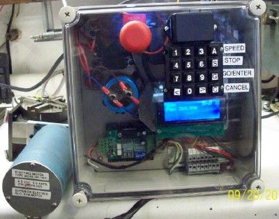
I included a 28VDC power supply in the control cabinet to make it completely self contained. The enclosure has a see through cover. I did this so only the keypad is exposed to the elements. I'm running 450 oz/in steppers.
The driver board is one of those Chinese board purchased on Ebay. I set switch 3 to ON and switch 4 to OFF. The controller was then set for
360 degrees = 12000 steps. I key in angular moves and it does it perfectly for the 30:1 worm gear.
Be sure to run a wire from the 5V terminal on Steves control board to the
COM terminal on the driver board. Chinese board specifies a 5V terminal.
Greatest challenge was the darn keypad I used the Apem keypad. Got it to work (help from Steve) then reverse engineered it by figuring out what the Pin outs were then switched to the keypad in the pic.
SEE IT RUN
Steve was lots of help and I appreciate it.
I have less than $100 in this project,,less the rotary table, also home made. Wanted to build one of these for 2 years. Now it is done.
Jimwww.outbackmachineshop.com
-
09-23-2013, 05:56 AM #736
Registered
- Join Date
- Mar 2003
- Posts
- 104
Steve; Originally Posted by kwackers
You need a Gecko 210 driver board. Open the case and there are jumpers for about 5 combinations from full step to microstep.
I got my Chinese driver board to work by setting switch #3 to ON and switch #4 OFF. Then with my 30:1 worm gear I set 12000 steps to 360 deg.
I love the stepper control.
Jimwww.outbackmachineshop.com
-
10-11-2013, 01:31 PM #737
Registered
- Join Date
- Sep 2013
- Posts
- 1
Hi Steve,
I've just returned to this thread after being away for a while. I built a similar keypad based on Khalid's design posted earlier, I used 6mm cheap pcb buttons for the keys and find them adequate. I did make the holes in the the casing 12mm diameter to make the flush buttons easier to operate. The casing is a bit on the small size but it was quite inexpensive from Maplin however I am making a replacement from some hardwood I have handy together with a sheet metal face to hold the keyboard and digital readout.
As you can see I used a cheap Chinese stepper driver and although I have not yet set up my rotary table the driver is capable of driving my chosen stepping motor. Below are some pictures including my new casing - the metal face was made from a defunct computer cabinet.
Attachment 204180, Attachment 204182, Attachment 204184,
Terry
- - - Updated - - -
-
11-25-2013, 06:30 PM #738
Registered
- Join Date
- Nov 2012
- Posts
- 3
What a great piece of equipment, thanks Steve for a great and easy to build design, heres mine:
Attachment 210274
Attachment 210276
Attachment 210278
Attachment 210280
Attachment 210282
Attachment 210284
Attachment 210288
Attachment 210290
Attachment 210292
Items used:
Old splicing box
Cheap TB6560 chinese driver
Stripped down 15v laptop PSU
Regards
Paul
-
11-25-2013, 11:34 PM #739
Member
- Join Date
- Jan 2006
- Posts
- 204
wow too cool
archie =) =) =)
-
12-16-2013, 11:30 PM #740
Registered
- Join Date
- Sep 2011
- Posts
- 22
Steve
I looked around on other forums, seems there is someone that managed to link a encoder to a stepper to cut gears.
I can send you the article if you pm me your email address.
Also would it be possible to add a menu on the controller so that one can select what helix angle to cut?
The helix angle menu must work together with the other menu`s so that one can still select number of teeth to cut.
Then there must be some kind of output that tells the stepper to move a certain amount of steps according to the encoder position and helix angle selected.
I`m willing to help where i can.
Dennis
Originally Posted by kwackers

 Reply With Quote
Similar Threads
-
Stand alone rotary table indexer.
By kwackers in forum PIC Programing / DesignReplies: 13Last Post: 01-29-2023, 03:01 PM -
CNC Rotary Indexer/Table
By desman in forum Commercial CNC Wood RoutersReplies: 2Last Post: 08-11-2015, 03:32 PM -
4th Axis CNC Rotary Indexer Table Plans
By Modular CNC in forum News AnnouncementsReplies: 4Last Post: 05-11-2011, 07:55 PM -
Manual indexer-rotary table vertical
By silverfoxx03 in forum Want To Buy...Need help!Replies: 0Last Post: 02-18-2011, 09:04 PM
