


Woohoo! Very nice, Guldberg!
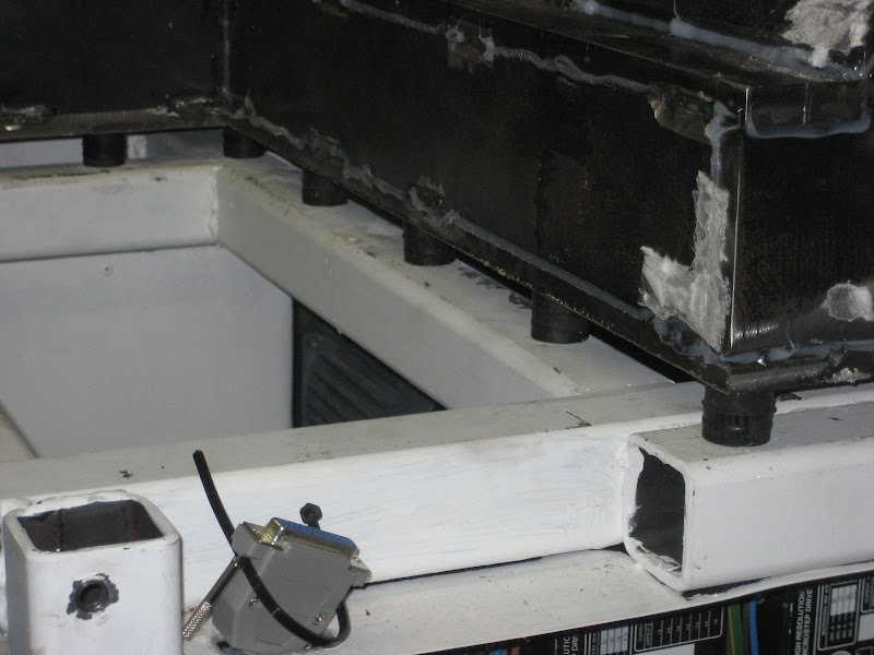
You've joined the E/G crowd now, and in first class fashion. I used GE silicone to seal the bays on my mill before filling:
Even so, the epoxy does go everywhere. That's a good thing, to a certain extent. It helps lock it in better when every nook and cranny is filled. But it is a mess in your shop. Hope you had some drop clothes!
Now I'll bet if you wrap that "polymer composite machine tool frame" with a wrench it sounds a lot more "dead" than it used to. 40kg of that stuff should really help!
Can't wait to see this lathe perform, but I bet you're even more impatient. Should be pretty sweet.
Cheers,
BW
Thread: Slant bed CNC lathe from scratch
Results 281 to 300 of 405
-
06-12-2009, 06:37 PM #281
 Gold Member
- Join Date
- May 2005
- Posts
- 2502
-
06-15-2009, 09:14 PM #282
Registered
- Join Date
- May 2006
- Posts
- 573
The machine is back standing on its own on a whole bunch of those vibration dampers
From CNC
The Z axis is up and running for the first time, I had some trouble aligning the ballnut bracket. Did a quick test, 10000 mm/min 500 in acceleration. No problem at all. Well almost. If it begins in one end at full speed, I can here some noise. I suspect the balls are getting locked up and not running around the ball circuit but rather just sliding along the tracks. This cant be healty for the ballscrew in the long run. I will try to lubricated better and run it at lower speed.

From CNC
-
06-16-2009, 07:09 AM #283
Registered
- Join Date
- Apr 2007
- Posts
- 90
Hi,
Happy to see your machine moving, how did you mix the EG? any type of mixer and did you do vibratory compacting to releive air bubbles from the mixture after the cast. In India we have no one selling epoxy like the ones you get but have to try with what is available in the market. how is the progress of on the spindle head, you could try with a pneumatic 3 jaw chuck which would be cheaper than a hydraulic system and would provide some precesion clamping.
-
06-16-2009, 07:38 AM #284
Registered
- Join Date
- May 2006
- Posts
- 573
I mixed it in a plastic container with a plastic spoon from ikea:-) Following Bobs advice, I did the work in batches of 5-600g each and one bay at a time.
-
06-19-2009, 05:40 PM #285
Registered
- Join Date
- Mar 2004
- Posts
- 1306
I wonder how much the EG will resist the movement of the welds as it ages. Certainly won't hurt
 Regards,
Mark
-
06-19-2009, 11:03 PM #286
Registered
- Join Date
- May 2006
- Posts
- 573
Times will tell. I would sure love to not have to mill it again:-)
Did some more work today. All these small brackets etc. takes up a lot of time, but its all worth it in the end.
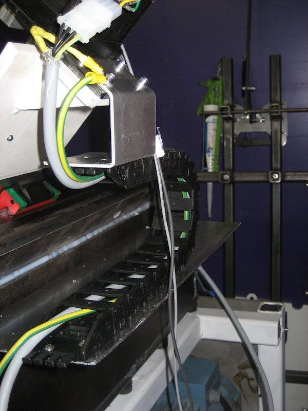
From CNC
With the energy chain in place I could install the cable for the x-axis motor and do the first simultaneous axis test
-
06-20-2009, 11:56 PM #287
Registered
- Join Date
- May 2006
- Posts
- 573
It beginning to look like something
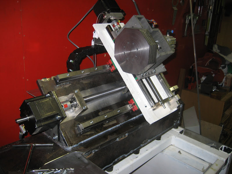
From CNC
-
06-21-2009, 04:59 AM #288
Member
- Join Date
- Sep 2006
- Posts
- 6463
Hi Guldberg, I hereby cristian it the "Rock of Unalter", LOL.
With all that stonework in the epoxy, one things for sure if a weld cracks or needs rewelding there's no way yo' gonna dig the stuff out.
It would be interesting, once the final count is made, just how much a project of this type would cost, IE. for when the orders pour in and you have to send out to get the productiuon up.
The first one is always the hardest, the rest are just a repetition, which means that now you have the means all the parts can be made in house etc.
Then you'll also need a CNC mill, CNC grinder, CNC robot welder...... piece of cake.
I reckon with the way world technology is at the moment, you'd be able to send a CadCam order to a supplier in China, and get a completely welded body by return post, wow, an instant CNC lathe in kit form, makes Leggo building seem complicated.
That tool turret looks interesting, hope it's rigid enough, the Achiles heel of any lathe is the rigidity of the toolpost.
There's nothing like a bit of deflection to ruin a good relationship.
Congrats, really looking good so far.
Ian.
-
06-21-2009, 09:55 AM #289
Member
- Join Date
- Sep 2005
- Posts
- 1195
About base
Guldberg,
In the end, the base is filled with stone,gravel, sand and mixture, etc. How much more expensive or difficulties if from the beginning you are using solid steel base? Or you have some considerations so that you should use stone filler.
It is very nice project.
Thanks.
-
06-22-2009, 10:58 AM #290
Registered
- Join Date
- May 2006
- Posts
- 573
The epoxy granit stuff is mainly added because of its vibration dampening properties. Steel has quite lousy properties when it comes to dampening, so making it out of solid steel wouldnt really do any good.
What would be the correct way to do it, would be to have it cast instead of welding it together. Cast iron has good vibration dampning properties compared to steel, but I dont have the equipment for this nor do I know where I could have it cast.
-
06-22-2009, 03:26 PM #291
Gold Member
- Join Date
- May 2005
- Posts
- 2502
Looking good!
Have you been thinking about way covers yet? Wouldn't want the goodies exposed to too many chips.
I always thought it would be fun to fabricate some sheet metal covers like the big guys use. The problem I kept coming across was how to keep the pieces aligned without too much resistance and scraping. Then I saw this picture of the underside of some Mazak covers:

Of course the traditional rubber works too!
Cheers,
BW
-
06-22-2009, 04:08 PM #292
Registered
- Join Date
- May 2006
- Posts
- 573
Waycovers have almost been the biggest concern in the design proces. I know from experience from the other machines i build how difficult it is to fit way covers if the machine isnt designed for it.
The way cover for the Z axis just be bended SS plates sliding in and out behind the headstock and the back of the machine. Vipers will hopefully keep most of the chips and coolant inside the machine, but i will also design a "return tray" to guide run away coolant back into the machine.
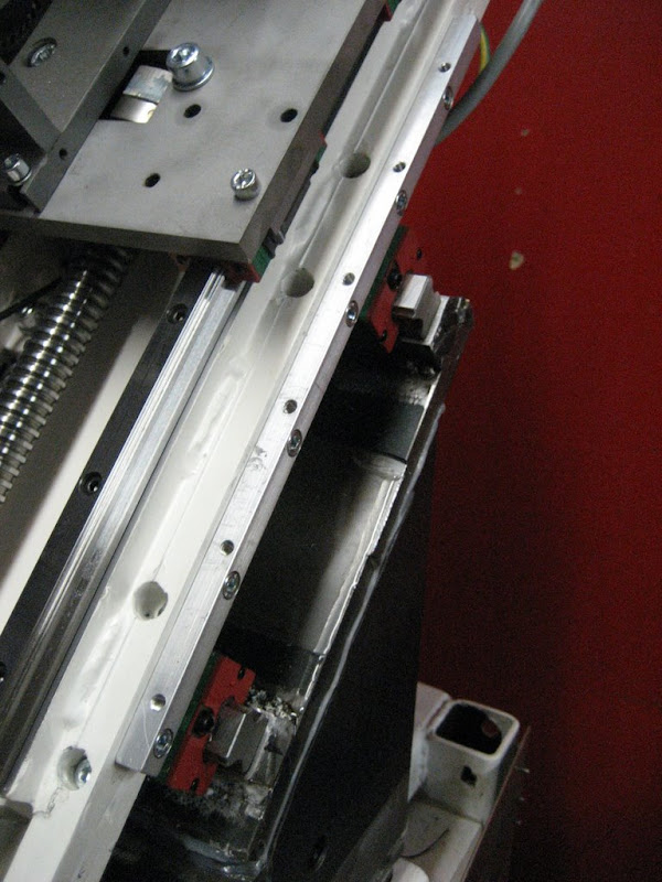
The X axis is a bit more tricky. The top part (behind the turret) will slide in and out behind the cover, just like the Z axis. The bottom part is more suited for a telescopic cover, but to start with im just going to use the same system as the other covers. A simple bended piece of SS. A telescopic cover is a little project in itself
You have to imagine most of covering in this picture, but you get the general idea
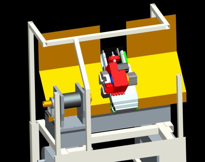
From CNC
-
06-22-2009, 04:43 PM #293
Gold Member
- Join Date
- May 2005
- Posts
- 2502
Cool!
If you enclose the machine, you may need more for the Z. I'm a little concerned about chips being able to "ricochet" around the ends of the covers.
I know from experience that with CNC, chips seem to go everywhere and you make a heck of a lot more of them than you were able to with manual!
:drowning:
My garage is covered now with chips in the most unlikely places.
Cheers,
BW
-
06-22-2009, 10:51 PM #294
Registered
- Join Date
- May 2006
- Posts
- 573
The covers on the CAD illustration is only some of the covers im going to install. If you look inside a real CNC lathe, you get a pretty good idea at what im aiming for. A total enclosure where coolant can splash anywhere without escaping.
But as you point out Bob, chips will somehow get to the linear bearings somehow, ive seen that looking inside the pro machines. I dont worry to much about that though, the lips on the linear carriages seems to do a good job at removing dirt and small chips before it ends up inside the carriage.
I actually started working on the covers today making a bracket that the Z axis covers will attach to. Im kinda postponing the spindle build because I have a tendency to jump to the next project as soon as the machine is making parts. Its better to get all those little things done first.
From CNC
Also today I did my first long running job on my mill. Total machining time was around 1:30h. Two different tools. I estimate that the ½ hour could be cut of since there was a lot of folish and time consuming toolpath, but since im only doing one I didnt bother to optimize the toolpath.
Its one part of the clutch for the turret. I forgot to leave some material when doing the rough cut, thats why you see some marks on the angled surfaces. Obviously you would harden and grind this kind of parts in "real life", but im sure this is sufficient for me
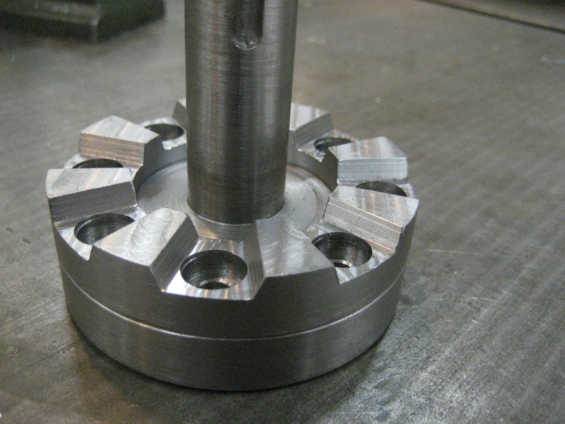
From CNC
-
06-23-2009, 10:41 AM #295
Member
- Join Date
- Jun 2006
- Posts
- 475
Excellent work Guldberg! I always enjoy reading your thread and seeing your great work. (Except for your welding (flame2) !!!! Haa Haa) No seriously it realy is a great thread. Keep up the good work and keep posting plenty pictures.
Chich
-
06-23-2009, 03:17 PM #296
Registered
- Join Date
- May 2006
- Posts
- 573
Haha. You are absolutly right. Its quite high on my list of things i need to learn. I know its just a matter of taking the time that is needed and practice. When I need to weld something, I usually just take the shortcut.
-
06-23-2009, 08:40 PM #297
Registered
- Join Date
- Feb 2006
- Posts
- 1072
Jacob, be sure to install plugs like these in the linear rail holes so that chips can't enter the carriages from below. They are unfortunately not available for my little 10mm rails so I'm turning my own from Delrin. Originally Posted by Guldberg

Randy
-
06-26-2009, 07:31 AM #298
Registered
- Join Date
- May 2006
- Posts
- 573
Thx for reminding me Randy. They came with the rails, but I have totally forgot them. I will make sure to plug the holes before any cutting
-
06-28-2009, 10:01 PM #299
Registered
- Join Date
- Feb 2006
- Posts
- 12
nice project! i've just read the topic from start to end (took 2 hours) but it was worth it!
i'm just curious about how you are going to align the spindle with the z-axis.
I figure it would be easy to stuff a big axle into the chuck, mount a measuring gauge in the tool holder, put it against the axle, and run the z axle back and forth checking the gage.
don't know if this is accurate enough though.
-
06-29-2009, 10:29 AM #300
Registered
- Join Date
- May 2006
- Posts
- 573
I think that is about the only way to do it for a hobbiest like myself and you can proberly get it within 0.01mm over a distance of 200mm. Pleanty of accuracy for me. I have a 25mm linear bearing rail that im going to use. The alignment gets a bit more complicated because the bed is slanted. This is the reason I wanted to have the base milled in a single setup. If there was a misalignment in the angle I would have to shim it. Now i can hopefully just adjust the headstock sideways.


 Reply With Quote
Similar Threads
-
CNC lathe scratch build!
By aarongough in forum Vertical Mill, Lathe Project LogReplies: 37Last Post: 02-07-2013, 10:06 PM -
Looking for Specs for a scratch built lathe
By breathe in forum Vertical Mill, Lathe Project LogReplies: 18Last Post: 06-16-2011, 12:56 PM -
From scratch. Lathe, Mill, or maybe both.
By MrBean in forum Vertical Mill, Lathe Project LogReplies: 27Last Post: 10-28-2010, 01:25 PM -
CNC Lathe from Scratch
By mackeym in forum Vertical Mill, Lathe Project LogReplies: 85Last Post: 06-02-2010, 12:20 AM
