


Well I've about drawn up the plans. Ordered the ball screws, rails and bearings. So now comes the fun part......putting it together.
Brad.
Thread: Spidey Costume
Results 41 to 60 of 81
-
09-06-2008, 10:01 AM #41
 Registered

- Join Date
- Feb 2008
- Posts
- 54
www.spidey4fun.com
-
09-06-2008, 12:54 PM #42
Community Moderator
- Join Date
- Feb 2004
- Posts
- 2337
Still watching Brad. You're posts are been taken notice of.
Nice design.
BennyBeing outside the square !!!
-
09-06-2008, 04:51 PM #43
Registered
- Join Date
- Feb 2008
- Posts
- 54
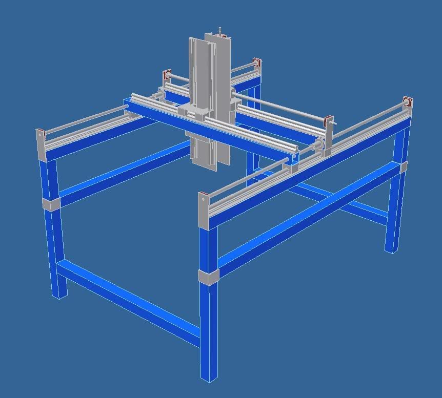
I just changed the design to have the gantry arms on the inside. This gives an extra 85 to 100mm cutting area.
Brad.www.spidey4fun.com
-
09-06-2008, 05:06 PM #44
Gold Member
- Join Date
- Sep 2003
- Posts
- 1113
How?
Don't the plates for the gantry "eat-up" the space on the Y axis?
Did you get/plan on longer rails and bits?Experience is the BEST Teacher. Is that why it usually arrives in a shower of sparks, flash of light, loud bang, a cloud of smoke, AND -- a BILL to pay? You usually get it -- just after you need it.
-
09-07-2008, 01:09 AM #45
Registered
- Join Date
- Feb 2008
- Posts
- 54
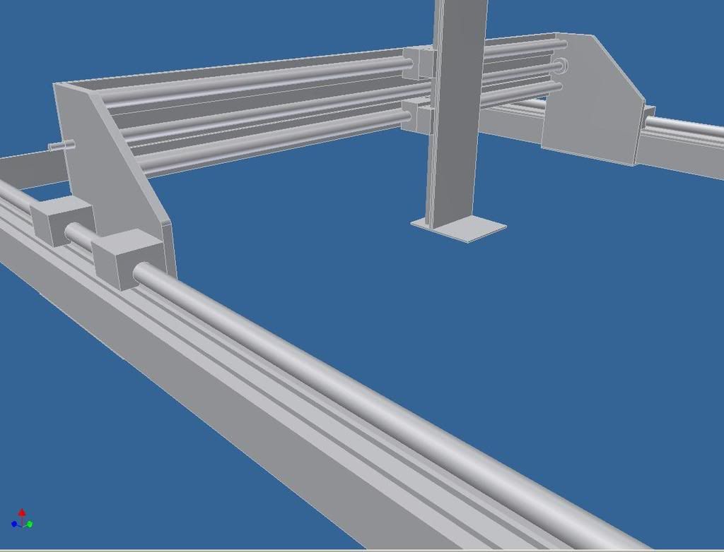
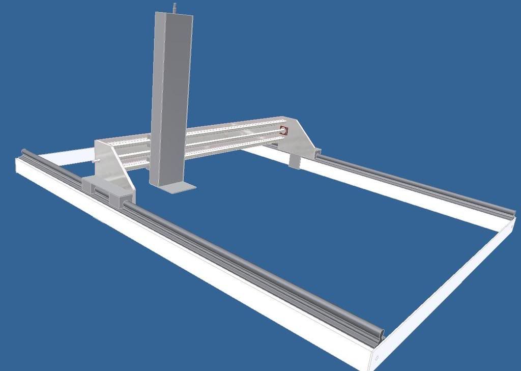
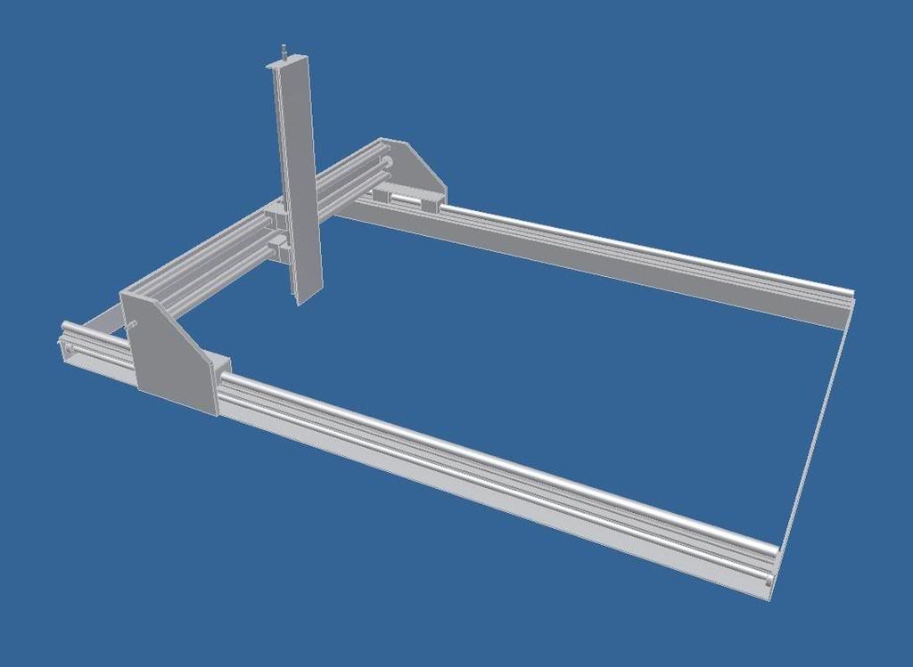
It's the same gantry. I just put the rails on the outside and made the base a little wider. So the rails wont get in the way of the Z-Axis. The Z-Axis is pretty long and I'll have the table below. Most like make it an adjustable height so on smaller / short jobs I'll have the table raised up which should reduce stress on the unit.
And again... slight modification. If I exend the rails a little more at the front I'll be able to get full range on the ball screws.
Brad.www.spidey4fun.com
-
09-07-2008, 02:35 AM #46
Registered
- Join Date
- Jan 2007
- Posts
- 355
Brad,
It's a beautiful design, and you've got me a little curious. I haven't seen any design with this much travel in the Z.
Need more info, Brad.
Are you using dual screws to drive the X?
Will the long Z axis be rigid enough?
Do you plan to use a router or spindle?
Just curious, Brad. I'm still gleaning ideas for my build.Diplomacy is the art of saying "Nice doggie" until you can find a rock. - Will Rogers
-
09-07-2008, 03:06 AM #47
Registered
- Join Date
- Feb 2008
- Posts
- 54
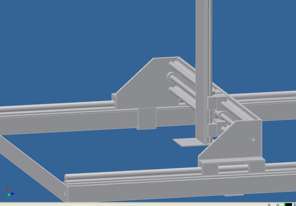
Rails all round. 20mm on the base, 16mm on the gantry and 12mm on the Z-Axis.
I make alot of molds and im moving in sculpting so I thought a longer Z-Axis would come in handy. Not sure about the router. I haven't looked into steel or aluminium yet so none of the framing is in scale. The rails, ballscrews and bearing are to scale from the manufactures specs.www.spidey4fun.com
-
09-07-2008, 06:51 AM #48
Registered
- Join Date
- Feb 2008
- Posts
- 54
Yep, duel screws on the X-Axis.
Brad.www.spidey4fun.com
-
09-09-2008, 04:14 AM #49
Registered
- Join Date
- Jun 2003
- Posts
- 453
Hi Brad,
it might be a good idea to design the y and z axis so that stiffening members can be added at a later stage if required. The back of the y axis could easily be converted to a box section, that's what I did on my machine to help make it more rigid.
Cheers
Dave
-
09-09-2008, 09:26 AM #50
Registered
- Join Date
- Feb 2008
- Posts
- 54
Yeah... good idea. I'll do some alterations and add another image or two.
 www.spidey4fun.com
-
09-09-2008, 01:55 PM #51
Registered
- Join Date
- Feb 2008
- Posts
- 54
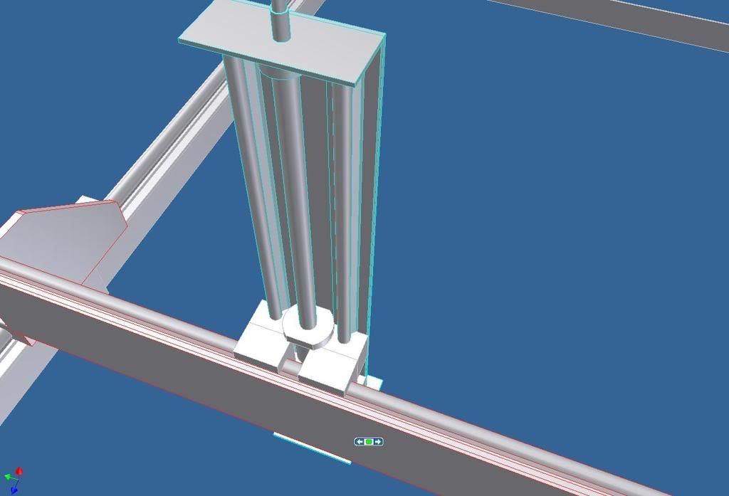
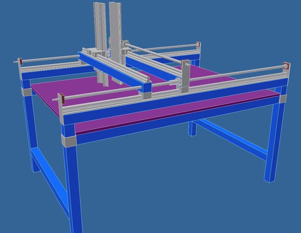
This should help on the Z-Axis.
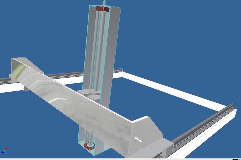
Brad.www.spidey4fun.com
-
09-09-2008, 02:37 PM #52
Gold Member
- Join Date
- Sep 2003
- Posts
- 1113
OK - that answered the question - obvious - but wanted to clarify.
With that tall Z capability - I guess you'll be mounting the entire framework on a raised rail bed? That is to say, long tall sides to support the x axis? [Otherwise the height (bottom) of the Y axis will be problematic.]
Also, WRT the tall Z axis - you'll want to understand the feed rate and the associate loads when deep cutting your materials -- or use soft materials and slow feed rate. The Y axis will get a lot of the transferred to it - and the errors most likely show as the X axis "dragging" under load.
Make sense ? - I haven't a picture for you but can make one if needed.
:cheers: JimExperience is the BEST Teacher. Is that why it usually arrives in a shower of sparks, flash of light, loud bang, a cloud of smoke, AND -- a BILL to pay? You usually get it -- just after you need it.
-
09-09-2008, 02:47 PM #53
Registered
- Join Date
- Feb 2008
- Posts
- 54
Hey Jim... A picture would be nice
 Yeah the X-axis will be sitting atop legs and the base of the table will most likely have an adjustable height. So when Im cutting shorter jobs I'll lift the bed closer to the gantry. To date I only cut into engineering wax and make molds.
Brad.www.spidey4fun.com
-
09-10-2008, 10:55 AM #54
Registered
- Join Date
- Feb 2008
- Posts
- 54
More changes. I went looking into steel today. I might use C section 125 x 65mm to support the x-axis. And 50mm sq. tube for the legs.
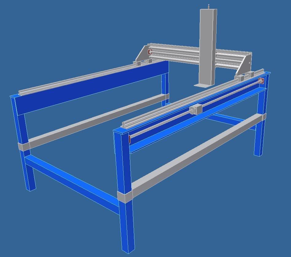
Brad.www.spidey4fun.com
-
09-12-2008, 02:10 PM #55
Registered
- Join Date
- Feb 2008
- Posts
- 54
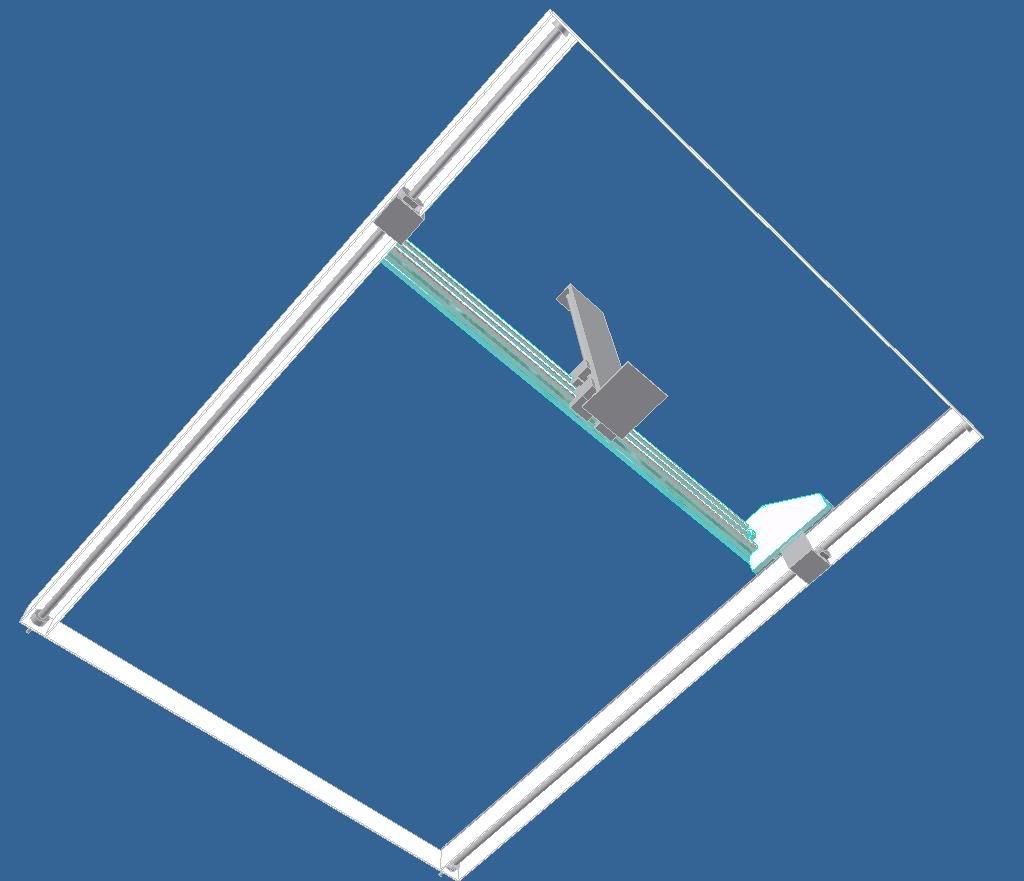
More changes.... I've put the ginder right in the middle to help balance it out.
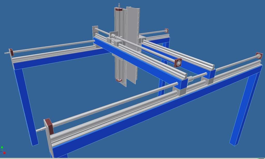
Brad.www.spidey4fun.com
-
09-12-2008, 03:21 PM #56
Gold Member
- Join Date
- Sep 2003
- Posts
- 1113
Sweet As!
I like it a lot Brad - you have a good counter to any workpiece loads torquing the Y Axis and messing up the X axis translating too!
Seems like a good solution when you have a "deep" Z axis.
:cheers: Jim
I bet you didn't show the endplates on the Y axis -- For Clarity?Experience is the BEST Teacher. Is that why it usually arrives in a shower of sparks, flash of light, loud bang, a cloud of smoke, AND -- a BILL to pay? You usually get it -- just after you need it.
-
09-12-2008, 04:26 PM #57
Registered
- Join Date
- Feb 2008
- Posts
- 54
Not Clarity.... just hadnt drawn them in...lol.
Brad.www.spidey4fun.com
-
09-13-2008, 07:46 AM #58
Registered
- Join Date
- Feb 2008
- Posts
- 54
Another picture.. Im thinking of maybe using 4 steppers and ordinary high tensile bolt thread to raise the lower the table. Not sure just yet.
 www.spidey4fun.com
-
09-18-2008, 10:30 AM #59
Registered
- Join Date
- Feb 2008
- Posts
- 54
The first lot of parts arrived the other day. Still waiting on another 2 rails for the Z-axis.
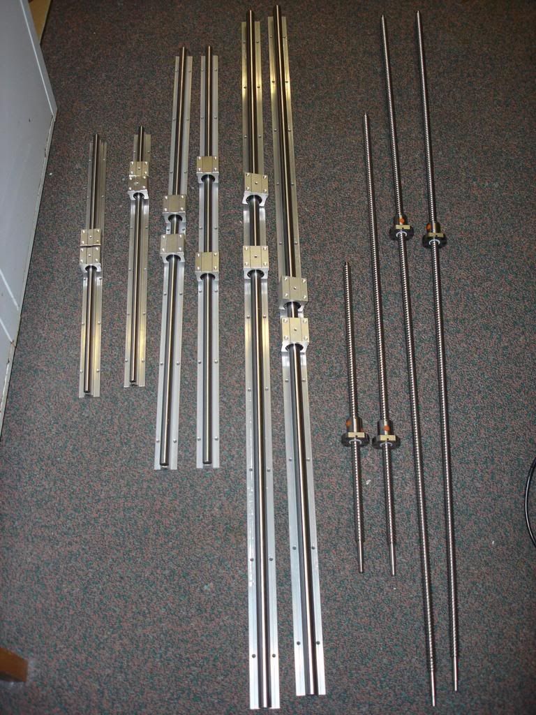
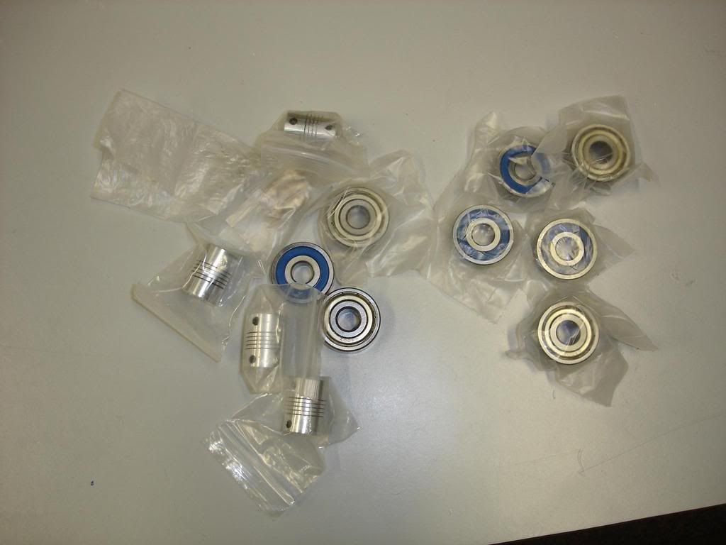
Brad.www.spidey4fun.com
-
09-18-2008, 10:51 AM #60
Registered
- Join Date
- Jun 2003
- Posts
- 453
 Originally Posted by spidey4fun

Hi Brad,
I think you're over complicating things with an automated table height control. I envisage something simple, maybe a four cable winching system which picks up on the corners to do the major movement then a threaded device which clamps to the table legs for the final adjustment. Maybe a touch probe like Greolts could be used. When I get some time we can sit down and look at a few options but right at the moment I'm busy busy busy building a furnace, and tying to sort out an issue which has cropped up on my cnc.
Cheers
Splint

 Reply With Quote
Similar Threads
-
'spidey' Scales Heights
By WallCrawler in forum Community Club HouseReplies: 0Last Post: 08-05-2004, 01:47 PM
