


I have a Shizuoka AN-S also. My unit uses a bandit controller but the wiring got pretty fouled up from the previous owner where do I find info on this EMC/PC controller?
I am also in need of an actual machine manual showing lube points etc.
Results 21 to 40 of 40
-
05-03-2008, 10:17 PM #21
 Member

- Join Date
- Nov 2006
- Posts
- 152
I used to be appalled, now I'm just amused.
-
05-03-2008, 11:08 PM #22
Registered
- Join Date
- Jul 2006
- Posts
- 98
KIMFAB,
The EMC2 website is here:
http://www.linuxcnc.org
There is a bootable LiveCD available that you can download. This can boot your PC and let you try it out without affecting your hard drive. When you want to install, just provide an empty partition and click the install icon.
I am not sure how much AN-S help I can be. I have an ST-N with steppers and three-phase drive. These mills seem to have come with different spindle and axis options. If you can provide more details and pictures, I'll be able to know what I can help with.
Kirk, http://www.wallacecompany.com/machine_shop
-
05-03-2008, 11:44 PM #23
Member
- Join Date
- Nov 2006
- Posts
- 152
I put in a vfd for the 3hp spindle works nice. Here's a picture. http://www.kimfab.com/images/shiz.jpg
I've got the servomotors with syncro resolvers but I don't think that matters much for the base machine. I would think the maintenance on the machine itself would be similar.I used to be appalled, now I'm just amused.
-
05-04-2008, 12:37 AM #24
Registered
- Join Date
- Apr 2008
- Posts
- 4
I am still collecting the pieces I need to do the conversion.
I got my VFD in yesterday. It was a new Orion VFD. I bought it a little oversized, it was rated for 3KW. The motor is only 2.2KW. Only paid $100 for it new. It does not have all the bells and whistles, but i think it will be functional for what I need. I will let everyone know how it goes.
I am still debating the whole stepper reuse. Right now I am in a time crunch. It may keep me reusing the stepper board. Kirk, thanks for the research into the boards. I really want to get rid of the whole bandit box. It just looks big and bulky and in the way.
Paul
-
05-04-2008, 12:55 AM #25
Registered
- Join Date
- Jul 2006
- Posts
- 98
KIMFAB,
That's an AN-S? It sure looks allot like my ST-N.
The only mill documentation I have are the installation notes and part drawings. The notes say:
" 1. LUBRICATION
All slideways are supplied with oil from the one shot lubrication pump on the left side of the column. The pump should be operated several times daily according to the type of work done. The capacity of pump is 0.8 liters and 1 shot flow is 7 cc. The recommended lubricant is MOBIL VACUOLINE OIL 1409. Other lubrication is not necessary for this machine."
That's all I got. I did look in the High/Low gearbox and found a light grease that had flowed to the bottom of the case. The gears looked pretty dry, so I brushed some of the grease back up to the gears. The motor and spindle bearings I think are sealed so they shouldn't need anything. The ballscrew bearings I believe are handled by the one shot. I did notice that the X axis ballscrew bearing on the lazy end has no seal, so chips can get in. It came from the factory this way, but I am thinking I should make a bearing cover.
Are you intending to use the Bandit or convert to another controller? The resolvers may be a problem unless you want to use expensive resolver to quadrature converters. On my Hardinge HNC lathe, I replaced the resolver/tachometers with U.S. Digital encoder parts:
http://www.wallacecompany.com/cnc_la...C/00001-1a.jpg
http://www.wallacecompany.com/cnc_lathe/HNC
EMC2 may be able to use your servo drives, but I am guessing that the drives need +/- 10 Volt analog input signals and you will need a hardware encoder counter. EMC2 can use use the parallel port for encoder input but the parallel port isn't fast enough for decent travel rates and resolution.
I just noticed in your picture that the coolant line is different than mine, so I now I believe that you have an AN-S. I was surprised to find that the base of my machine is the tank for the coolant. What a pain to clean.
I have the manual with schematics for the tool changer. It should be easy to convert. One reason I converted from my Bandit was that the tool changer only had home and tool forward or reverse. It was necessary to keep track of the tool movement to get the needed tool. The speed changer is the same way, but with EMC2, a VFD and analog card, I can call a speed by S number. I am going to add a tool slot encoder, so that I can call a tool by T number.
Please post any progress you make on your machine.
Kirk, http://www.wallacecompany.com/machine_shop
-
05-04-2008, 02:26 AM #26
Member
- Join Date
- Nov 2006
- Posts
- 152
kirk_wallace
Not sure what I will do yet. I'm getting short on time. Would like a kit of some sort so I don't have to re engineer everything.
Just looked outside did not see any pigs flying overhead so looks like the kit idea is out. My servos have room and a good mounting system so I think I can pull the resolvers off and replace them with encoders. The servos are labeled for 140 volts so I'll need a hefty driver. The machine has a Quickdraw tool changer that appears to be a separate part. I have a manual for it but the buttons on the bottom of the front panel are all gummed up and I think possibly broken.I used to be appalled, now I'm just amused.
-
05-04-2008, 07:13 AM #27
Registered
- Join Date
- Jul 2006
- Posts
- 98
KIMFAB,
I use these amps on my servo machines:
http://pico-systems.com/pwmservo.html
and this controller:
http://pico-systems.com/univpwm.html
Everything that you would need to do to get your machine converted has been done before, so there should be no magic. Except for the Z axis. I assume you will drive the quill, so you will need to find a motor, pulleys, belt and mount. This could take some days to make. Do you have a belt reduction for your current motors, or are they directly coupled to the ballscrews? I prefer mounting the encoders to the ballscrews. In my opinion it is a good compromise between accurate motor motion feedback and table position feedback. Mounting to the ballscrew can be easier too. I use a three or four to one ratio between the motor and screw.
The Quickdraw is controllable with a parallel port breakout board. It can be wired for 220 VAC, so my changer, stepper supply and VFD run from the main relay and my PC even runs on 220, but it is wired before the relay so I can run the PC with the machine off. There are changer input wires, one each for carousel CW, carousel CCW, carousel home, tool in and tool out. A function is invoked by shorting the function's wire to the common wire. There is one output wire that the changer pulses when the function is completed. I should have the software for EMC2 completed soon or each wire could be controlled with user definable M codes with another code that waits for a pin going high. I prefer calling a tool by a T number, so I will install a tool slot encoder and software like I have on my Hardinge lathe:
http://www.wallacecompany.com/cnc_la...C/00025-1a.jpg
http://www.wallacecompany.com/cnc_lathe/HNC/
My buttons were sticky too. The buttons pull off towards you. I cleaned mine and they are okay. They may work better right or wrong side up. If needed, you should be able to buy equivalent switches. I think that the panel is in a bad spot and I may just put a cover over the panel and operate the changer through the manual mode in EMC2.
Kirk, http://www.wallacecompany.com/machine_shop
-
05-04-2008, 05:43 PM #28
Member
- Join Date
- Nov 2006
- Posts
- 152
I have the servo and drive mech for the quill. It is on the bench so is not in the picture. The x and y is direct drive. There is a set of Glentek servo amps in the bandit box - probably a later edition to the Bandit. Thanks for the link to the Pico systems, their web pages appear to be a work in progress tho. I will probably check closer into their controller. Have to look closer into the ATC if it is indeed just a contact thing should be able to work around it maybe just set up a new front panel. Thanks again for the info.
I used to be appalled, now I'm just amused.
-
05-08-2008, 06:05 AM #29
Registered
- Join Date
- Apr 2006
- Posts
- 14
 Using Bandit drivers & Mach3 with Hardinge HC
Kirk:
I have a Hardinge HC lathe (converted to CNC in its past) that has a Bandit control that died (computer part), but the driver cards (look similar to yours) are still good (I think). When I turn the control on, the steppers get rock hard and impossible to turn by hand.
I have the Bandit manuals (from ShadowCNC.com - Ken Albright). So, I am looking at the schematics for my driver cards and trying to relate them to your colored schematics. I am not being very successful.
I would like to use a printer port breakout board and connect it to the driver cards. On one of your pictures 00011-1a.jpg I saw three of those little white electronic bread boards connected to the ribbon cables that go to the main driver card. I noticed that you did not use a breackout board, but just have cables coming out of your PC (parallel port?). Your schematic does not show where the ribbon cable is hooked up etc.
I need the breakout board to control other items like speed contro and limit switches and read the spindle encoder. Is it possible that you have more of the actual wiring schematic you used.
I have a list of the ribbon connector pins going into the Bandit driver card:
1 PHB1 These three connect (eventually) to B1, B2 outputs to stepper
motor
2 PHB2
14 PHBC
3 PHA1 These three connect (eventually) to A1, A2 outputs to stepper
motor
4 PHA2
15 PHAC
5 12 V on motor logic (says +E in that schematic), but does not seem to
be connected to driver card that I can see, but may have been left off.
6 REV Inside motor logic is connected to 16 across a diode in /
transistor out - looks like Opto-isolator, but inside motor driver it is connected thru resister to TB1 Rev Lim
7 FWD Inside motor logic is connected to 16 across a diode in /
transistor out - looks like Opto-isolator, but inside motor driver it is connected thru resister to TB1 Fwd Lim
16 LIMCOM goes to +E
8 GND
9 ENAL 9 & 10 are connected thru diodes to +E and motor current pot
and lots of other circuitry including the AA (COM) & BB (COM)
10 ENAH
11 GND-X From motor logic, but driver schematic does not show
connections to driver card
12 NC
13 NC
If I can talk you into letting me see the circuit from the parallel port all the way to the driver card that would be really great. I may still have to bug you some more however.
Are you in the SF bay area?
I have been wanting to get this lathe working for 4 years. Some of that was modifying the mechanics to get more "out" travel on the cross travel so I can do larger long rounds.
Any help would be really helpful. I would like to go with Mach3 since that seems easier to me, and I know Windows much more that Linux.
- John
-
05-08-2008, 09:20 PM #30
Registered
- Join Date
- Jul 2006
- Posts
- 98
Hello John,
(BTW, Did you see my HNC here?:
http://www.wallacecompany.com/cnc_lathe/HNC/
but your lathe is probably more like my Feeler on the right background here:
http://www.wallacecompany.com/cnc_lathe/00006-1a.jpg
)
I got the Shadow (Bandit clone) user manual from here:
http://www.shadowcnc.com/manual.htm
Do you have the schematics for the Bandit system? If so, if I could see the driver schematic I could tell if it is similar to my drives. Your drives look like this?:
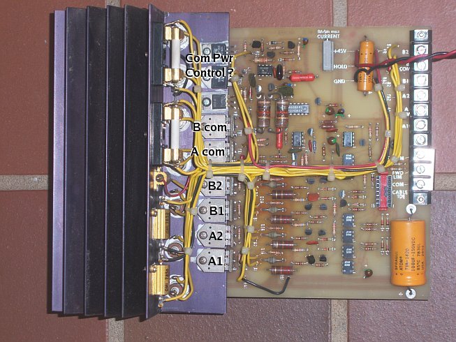
I am using a breakout board in this shot, but I should explain what's what:
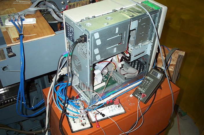
The breadboard on the upper left is just for connecting the original ribbon connectors to the Cat-5 cables. The ribbon cables weren't long enough to get to the PC. The Cat-5 goes to the lower left breadboard which has 74LS541 driver chips that buffer all of the printer port output pins. I have a few opto-couplers that control the serial DAC card near the spindle VFD. I would normally have opto-couplers with 12 Volt ouptuts going to the stepper drivers but they have opto's on their inputs already, and eventually, the cables will be short. The breadboard on the lower right has a charge pump circuit that uses a watch-dog signal from EMC2 that makes sure I don't activate the main power relay until EMC2 has started running.
So, the short version is, I drive the stepper drives with a standard buffered parallel port break-out board without opto-isolation.
As for your ribbon cable list:
"
I have a list of the ribbon connector pins going into the Bandit driver card:
1 PHB1 These three connect (eventually) to B1, B2 outputs to stepper
motor
2 PHB2 (kw: I concur)
14 PHBC (kw: I have this labeled as B Inhibit)
3 PHA1 These three connect (eventually) to A1, A2 outputs to stepper
motor
4 PHA2 (kw: I concur)
15 PHAC (kw: I have this labeled as A Inhibit)
5 12 V on motor logic (says +E in that schematic), but does not seem to
be connected to driver card that I can see, but may have been left off. (kw: not connected on my boards either)
(kw: I need to check, but I seem to recall 6 and 7 might be signals to the controller, maybe for current limit alarm or similar. I am not currently using these)
6 REV Inside motor logic is connected to 16 across a diode in /
transistor out - looks like Opto-isolator, but inside motor driver it is connected thru resister to TB1 Rev Lim
7 FWD Inside motor logic is connected to 16 across a diode in /
transistor out - looks like Opto-isolator, but inside motor driver it is connected thru resister to TB1 Fwd Lim
16 LIMCOM goes to +E
8 GND
(kw: I have 9 and 10 labeled as *SELECT and RUN/*STOP. I currently only use it as a drive enable)
9 ENAL 9 & 10 are connected thru diodes to +E and motor current pot
and lots of other circuitry including the AA (COM) & BB (COM)
10 ENAH
(kw: I have 5, 11, 12 and 13 not connected on my boards)
11 GND-X From motor logic, but driver schematic does not show
connections to driver card
12 NC
13 NC
"
In scoping the Bandit signals, the A1, A2, B1 and B2 seemed to follow a quadrature or half step configuration, but at low speeds the Inhibit signal pulse (pins 14, 15, or phase A and B common) was up to 50% of the step pulse width and decreased to zero at about half way to the max 100 IPM. I took this as a transition from half stepping to full stepping. I only have half stepping in my setup and I can get upto 70 IPM before losing steps. It would be nice to figure out how to do the step change, but right now it's not worth the effort and I will most likely go to servos in the future.
I really should start putting a system schematic together, but I don't have one for my HNC and it has been (almost) done for a while. I'll see what I can do. I am glad to help out wherever I can, but I am much more adept at EMC2, which I think is much more flexible. The little bit of Linux you need for EMC2 an average user can pick up pretty quickly.
I sort of live near San Fransisco, actually east 150 miles next to Yosemite Park.
Kirk, http://www.wallacecompany.com/machine_shop
-
05-08-2008, 11:32 PM #31
Registered
- Join Date
- Apr 2006
- Posts
- 14
My Hardinge HC CNC & Info
Kirk:
Thanks for the reply. I did see your lathe. I understand (and from your pictures), that a lot of it is run by air. Mine is older but does not use air for anything. I would like to build an enclosure to keep chips from flying all over my wifes stuff.
I have not placed any pictures on this forum before so here goes. I attached them since I can't figure out how to cut and paste (if that is an option).
The head view shows a standard HC head. There is an encoder on the rear that I will use to monitor the RPM and for threading.
The carriage views show a rear extension that holds the X drive stepper motor. I extended it 4 inches (was 26 lbs of AL but now about 12 lbs) to allow the turret to come out further (added an extension under the front end to support it too which is visible). Note that the turret is out beyond the bed. I had to make a ball screw extension as well. Before I hooked up the motor, the dial turned the ball screw soo smooothly and easily. I also have a Bridgeport Series I CNC mill which eventually will need a Mach3.
EDIT: I forgot to answer you about the driver card. Mine look identical to yours. The manual says they are #214-072-01 (says 5.5 amp max), however mine say 8.0 amp max, so they may be -02 version.
The schematic is attached as well. I hope you can read it. The manuals read as if they were for a mill, not a lathe. But, hopefully that won't matter.
For my purposes, a block diagram with pinouts would be perfectly acceptable instead of a schematic. If that is something you could sketch up easily, without taking a lot of your time, that would be great.
Edit: I realized that you are using the 74LS541 drivers on your breadboard as what would be in a standard breakout board.
The upper breadboard is only to allow you to tie the cables to the ribbon cables. So the only thing that is new is your little breadboard. EDIT: I guess your little schematic is for that. I am not sure how it is hooked up. The inputs are on the left (A1, A2, A inhibit etc.) go to where? The transistors on the other side (T5 sticking out) - are they on your driver card? - Sorry, I am a bit confused.
I noticed another person in the same forum with the same lathe as me (HC) with his bandit control having died as well. He may want to do what you did which is to just use the bandit drivers since they are all hooked up and probably still work. I have another Bandit control for a mill which does not work which I can keep for spares.
I did not see a breakout board on the back of your PC, but the cables look like they are plugged into the parallel port directly. Whose breakout board did you use? See Edit above.
The reason I want to go with Mach3, is that everthing else I do is via Windows (I use BobCad currently).
Thanks for all your help. Are you in Oakhurst? I almost moved out there (beautiful). I live in Sunnyvale, on the SF penninsula. If you are ever over here look me up.
Edit: Maybe I should call you one evening if that would make things easier.
- John
-
05-09-2008, 02:54 AM #32
Registered
- Join Date
- Jul 2006
- Posts
- 98
Thanks for the schematic. The schematic I made shows part of the input circuits which I reverse engineered from the drivers I had. Your schematic shows the whole board. If it happens to be convenient, is there a chance that a higher resolution copy could be made?
Sorry for the confusion about the driver hook up. Basically all I have is the parallel port (three ports actually), a buffer chip and the driver board input. One parallel port pin for each A1, A2, B1, B2 and Enable for each axis. It won't do you any good, but here is the portion of my config fill that assigns the pins:
...
# connect enable signals for step generators
net Xen axis.0.amp-enable-out => stepgen.0.enable parport.0.pin-01-out
net Yen axis.1.amp-enable-out => stepgen.1.enable parport.0.pin-06-out
net Zen axis.2.amp-enable-out => stepgen.2.enable parport.0.pin-16-out
# connect signals to step pulse generator outputs
net XphaseA stepgen.0.phase-A => parport.0.pin-02-out
net XphaseB stepgen.0.phase-B => parport.0.pin-03-out
net XphaseC stepgen.0.phase-C => parport.0.pin-04-out
net XphaseD stepgen.0.phase-D => parport.0.pin-05-out
net YphaseA stepgen.1.phase-A => parport.0.pin-07-out
net YphaseB stepgen.1.phase-B => parport.0.pin-08-out
net YphaseC stepgen.1.phase-C => parport.0.pin-09-out
net YphaseD stepgen.1.phase-D => parport.0.pin-14-out
net ZphaseA stepgen.2.phase-A => parport.0.pin-17-out
net ZphaseB stepgen.2.phase-B => parport.1.pin-01-out
net ZphaseC stepgen.2.phase-C => parport.1.pin-02-out
net ZphaseD stepgen.2.phase-D => parport.1.pin-03-out
...
The breakout board is the middle breadboard. The short blue parallel port cables go to the input side of the 74LS541 buffers. The long cables come out the output side of the buffer chips and disappear behind the orange cabinet for a little while and go to the upper bread board/connector. The breadboard with the meter connected to it is the watchdog charge pump.
EMC provides the half step signals. I don't know if Mach can put out quadrature (half step) signals. It may only output step and direction. I met Daniel Bernesi <[email protected]> on eBay and he said he had step/direction converters for his Bandit drivers. He may be able to tell you where he got his. I don't know if they are half or full step type. This should be a simple circuit to make, I just didn't bother. Plus getting the quadrature signals directly from the (slow) parallel port doubles the available step rate.
(BTW, I live in Groveland. here:
http://www.mapquest.com/maps/groveland+ca/
I grew up in Sunnyvale and went to Fremont High School. I really liked the old Sunnyvale. I like the new Sunnyvale too, but somehow the size of everything shrunk. Vince Endter, in San Jose, should be close to you. He has a thread covering his CHNC with servos, but he is using Mach:
http://www.cnczone.com/forums/showth...=50685&page=17
)
Kirk, http://www.wallacecompany.com/machine_shop
-
05-10-2008, 01:59 AM #33
Registered
- Join Date
- Apr 2006
- Posts
- 14
Bandit stepper drivers info
Kirk:
You won't believe this. I went to Fremont High School in Sunnyvale - graduated in 1966. I then went in the Navy in Jan 1967 for almost 4 years and came back home, went to De Anza College, and then San Diego State. When were you at Fremont? My wife went there also.
Groveland is actually pretty close to Oakhurst. I have been out 108/120 so many times (past Knights Ferry), so I have probably been through your town. I wouldn't mind moving out somewhere there where I can see the stars (I am an amateur astronomer).
Thanks for the other person's email address. I am starting to get the picture. The other light that dawned on me, is that the inputs to these boards must just be TTL (I know DUH). So, I should be able to get someone's standard breakout board, and hook up the Bandit driver inputs like you did and make changes to Mach3's output settings until I get a stepper to move. Does that sound right?
Send me a CNCZone message with your home email address (and phone number if you don't mind talking a bit), and I will scan the schematic at higher resolution and send it directly to you since CNCZone has a size limit. It won't get too much better however because the schematic is a copy of a copy of a copy. If we could get an original that would be great.
- John
-
05-11-2008, 05:47 AM #34
Registered
- Join Date
- Jul 2006
- Posts
- 98
Modesto and Sonora are starting to throw off noticeable light pollution.
I checked the Mach manual. They do let you assign signals to whatever parallel port pins you want to use, but it seems to indicate that Mach outputs step and direction signals only. You should contact Mach to see if they have a way to output a half-step (quadrature) sequence. Or look for a step/direction to half-step converter. You will lose half of your maximum step rate with step/dir though. The converter might be as simple as a flip-flop and a nand gate. I haven't done enough thinking or research to have a circuit yet. A down side to the half-step is that it will take up four pins, as opposed to two pins for step/dir, on your parallel port. EMC2 can run eight ports so I am okay at three ports on my mill so far.
The driver board inputs are designed for 12 volt signals. TTL max's at 5 Volts, but so far TTL seems to work. The driver has opto-couplers on the inputs so all you need to do is turn the opto-coupler's LED on and off. The voltage has to go through a diode which I don't know why it's there, other than to protect the opto-coupler LED from reverse voltages. Then through a 1k Ohm resistor and the opto-coupler LED. I think the diodes typically have a voltage drop of .5 Volts. V = I x R, V=(12 V - .5 V - .5 V) = 11 V across the input resistor which I think is 1000 Ohms, 11 = I x 1000 or 11 / 1000 = .011 Amps or 11 mA, which seems to be about the middle of the LED's range. For TTL or 5 Volts, 5 - .5 - .5 = 4 V, 4 / 1000 = 4 mA. I think the opto-coupler LED should work down to .5 mA.
I wouldn't worry too much about the schematic. I was hoping to be able to read what the component values where in case I needed to some day replace a broken part. Hopefully, I will have servos in place before the steppers give out. Thanks.
Kirk, http://www.wallacecompany.com/machine_shop
-
02-27-2009, 06:57 AM #35
Registered
- Join Date
- Jun 2007
- Posts
- 13
 A BIG Thank you!!!
Hello all! It's me... the guy who started this thread. I just wanted to say thank you to everyone that replied. They did turn out to be steppers and I didn't end up using them. I bought the following to replace them:
Keling Tech Drivers Model: KL-11078 Microstepping Driver
Keling Tech Steppers Model: KL42H2150-42-8A
Those are being run by a CNC Brain.
Electronically my ST-N is working great now. I'm having some issues with low/high speed select on the machine though... my machine was in pieces when I got it and I haven't been able to figure out how to put the gear box together and be able to switch from low to high. It seems as though it may have been modified but I can't tell for sure without having another ST-N to look at.
I'm glad to finally have my ways working and will be even happier once I can figure out this last little snafu.
Thanks again to everyone for the help... I'll be sure to post some photos once it's running fully.
Best Regards,
David
-
02-27-2009, 07:36 AM #36
Member
- Join Date
- Nov 2006
- Posts
- 152
Yea finally got mine finished too. will post pics on my web page when I get back. I already did 2 jobs on it. I cleaned up the Glentek amps and got them to work good and then went and bought a Shadow. I had some grounding problems at first but it is now running. Doesn't have the fancy graphics but is solid as a rock. Programs easily and has unreal power and response. My first crash sent a broken bit flying at almost bullet speed. I'm working on the spray coolant system now.
I used to be appalled, now I'm just amused.
-
02-27-2009, 08:29 AM #37
Registered
- Join Date
- Jun 2007
- Posts
- 13
That's great about your machine! I can't wait for the day I can say I've done something with mine. I'll be looking forward to seeing those pics... and I expect some of the shield you made to protect yourself from flying bits. :-O
-
02-27-2009, 10:03 AM #38
Registered
- Join Date
- Feb 2009
- Posts
- 4
 hello
hello
hi guy,
i am pleased that i join you today.so if you boys have any questions about servo motors and drives or controllers,just can ask me...maybe i can help you.
nancy
-
04-21-2009, 03:43 AM #39
Registered
- Join Date
- Apr 2009
- Posts
- 27
Hi everyone, i'm new here too. This thread convinced me to join, but looks like a great site overall.
I am planning on a Mach 3 retrofit on my Bandit controlled Shizuoka mill.
Should be interesting. I'm not too concerned about the stepper motor drives, but the tool changer and spindle rpm servo should be fun.
Thanks again for all the great info!
Daniel
-
05-06-2009, 03:55 AM #40
Registered
- Join Date
- Feb 2009
- Posts
- 4
welcome to www.torkmotion.cn
A motor manufacturer specialized in manufacturing DC brush, brushless servomotor.

 Reply With Quote
Similar Threads
-
Two servos on one drive?
By protman16 in forum Servo Motors / DrivesReplies: 6Last Post: 05-29-2008, 07:23 PM -
Spindle orient failure on Shizuoka B-3v with 6m
By kstocklin in forum FanucReplies: 0Last Post: 11-14-2007, 10:51 PM -
Baldor Servos And Drive
By Cycle Start in forum Servo Motors / DrivesReplies: 0Last Post: 05-29-2007, 01:28 PM -
Direct drive servos
By pstockley in forum Servo Motors / DrivesReplies: 11Last Post: 04-27-2006, 02:01 PM -
Servos and drive help
By tdpyro in forum Servo Motors / DrivesReplies: 3Last Post: 03-14-2005, 06:35 PM
