


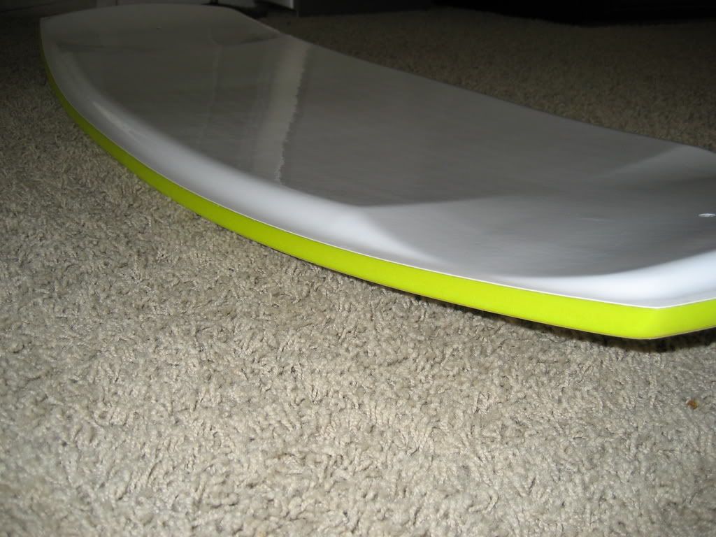
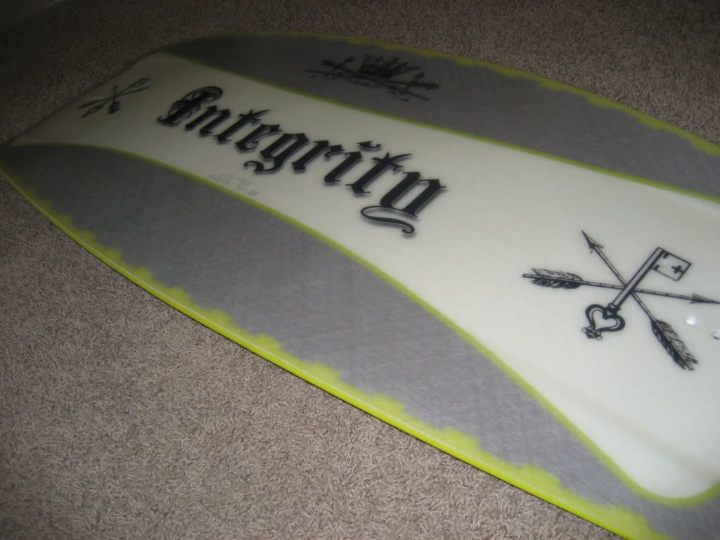
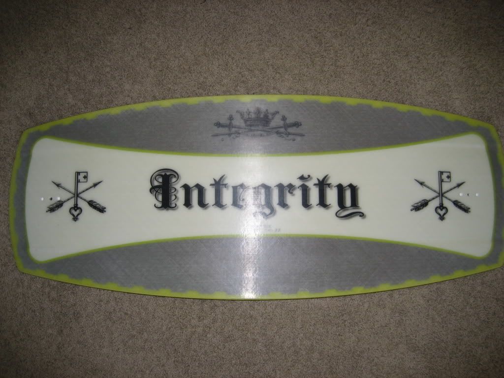
Can anyone point me in the right direction for creating a concave on a surface. I am looking to make contours on the top of a slab that looks like the top of a skateboard.
Here is the board that I wanted to add concave to, I would want the parrellell ends to have the same concave, but the kicktails are going to have a little more height than the sides.
Any help would be greatly appreciated!
Results 1 to 16 of 16
-
03-07-2008, 08:14 PM #1
 Registered
- Join Date
- Feb 2005
- Posts
- 61
Newbie question - Create a concave?
www.NeustonBoards.com
Mike
-
03-08-2008, 06:32 PM #2
Moderator
- Join Date
- Sep 2005
- Posts
- 1660
Can you give us a little more detail, maybe sketch on the photo w/ paint? There are several ways to ad curvature to a flat slab like that but I'm not understanding exactly what your looking for.
JerryJerryFlyGuy
The more I know... the more I realize I don't
(Note: The opinions expressed in this post are my own and are not necessarily those of CNCzone and its management)
-
03-08-2008, 07:54 PM #3
Registered
- Join Date
- Feb 2005
- Posts
- 61
Sorry for the minimal detail. I have been monkeying with it and kind of got what I wanted, but still not quite getting it.
Here is a basic idea of what I want the top to look like (just the top surface, pay no attention to the pocket in between the two boards in the picture):

Here is a picture of what I'm currently working on below. I cut a 30ft radius into the top of the board, but that leaves the ends still flat. I think I could do it, I just goofed when I chamfered the edge - I tried to sketch a simple triangular ramp for the ends and then do an extrude/cut, but everytime I would do it the extrude would follow the chamfered edge and run 45* to the top surface of the board:www.NeustonBoards.com
Mike
-
03-08-2008, 08:01 PM #4
Registered
- Join Date
- Feb 2005
- Posts
- 61
Here's another angle on the top contour:
 www.NeustonBoards.com
Mike
-
03-08-2008, 09:20 PM #5
Registered
- Join Date
- Feb 2007
- Posts
- 162
Something like the attachment?
This was sketched with one spline curve and 3 control points, not counting the endponts, on the RIGHT plane. The feature was extruded midplane and the thin feature was extruded midplane.
When creating a model like this one, you sometimes have to do the curvy stuff first, then add or remove features to get the results you want.
Scott
..here's a link to a very good lesson for curvy stuff.
some older lessons, but good basic concepts.
http://www.dimontegroup.com
Solidworks tutorials
...and new updates too. I have something else to do on a snowy day ;-)
...oops...I just noticed the curve goes the other way.Some of my best finds were in the trash....
-
03-12-2008, 11:24 PM #6
Registered
- Join Date
- Feb 2005
- Posts
- 61
So would there be anyway to setup the top surface concave on a flat surface/plane, and then could I manipulate the bottom contour?
The reason I ask is because it would be nice to have the basic concave on the top, but be able to tweek how the bottom of the board curves (which would then change the top surface just a little bit). I wanted to setup a few prototypes that all would have the same top surface, but the angle at which the tips raise on each end would be slightly different.
Here's a much better picture of what I'm trying to accompolish, shape/contour/everything, how would you all setup this board in solidworks?
So is there anyway to do that in solidworks, or would I basically be going into SW everytime and having to recreate the spline curves to meet my angle tolerances?
Thanks so much for all the help, I truely appreciate the input!
Mikewww.NeustonBoards.com
Mike
-
03-12-2008, 11:48 PM #7
Moderator
- Join Date
- Sep 2005
- Posts
- 1660
Mike it all depends on how detailed you want to make it. Typically on a CAD model of something like that your talking about alot more detail than just a couple sweeps and lofts, but rather boundry surfaces, fills, deleted surfaces, free form adjustments etc etc.. do you can curvature continuous surfaces etc..
Can it be created in SW, for sure. Can it be done in a couple features.. not likely.. is it a ten minute job.. no.. but then again.. if your wanting just the rough look and aren't going to machine something from you model.. then it probably is..
It all depends what your desired end result is..
JerryJerryFlyGuy
The more I know... the more I realize I don't
(Note: The opinions expressed in this post are my own and are not necessarily those of CNCzone and its management)
-
03-12-2008, 11:55 PM #8
Registered
- Join Date
- Feb 2007
- Posts
- 162
Yes, Solidworks can do this.
What version are you using?
You may want to setup the model using a master sketch that defines the length, width, thickness and curves that define the top and bottom shapes.
From there, anytime you want to make a change you would add a configuration based upon the master sketch and base extrudtion. This is a bit advanced for a new user, but there is no reason for a new user not to start with advanced modeling. You have a need and an idea so that will be the movation to learn. I'm no expert at the surfacing, but I want to improve my skills and I'm willing to help.
ScottSome of my best finds were in the trash....
-
03-13-2008, 01:01 AM #9
Registered
- Join Date
- Feb 2005
- Posts
- 61
Thanks so much for the reply's. Sorry, I should have clarified this in the first post...The reason I am doing this model is to CNC it out of a a raw piece of wood.
The reason I ask if there is a 'quick' way to remodel the original design is because I will want to make little tweaks to the design of the rocker (which is the angle at which the bottom face rises on each end). and when I do such a tweak to the bottom this will completely change how the board will ride and react with different forces in the water (this board is going to be used behind a boat, basically like skateboarding on water). And as always, my first attempt will likely not be what I want, so I'll have to revamp the design (again and again and again ). So that is why I just wanted to make sure with you all that there wasn't a quick 3D model manipulation that I am missing out on which could be used to revamp my design quickly (whether that be a simple angle adjustment to the bottom, or a total reshape of the bottom rocker).
I have a friend who is rather proficient with SW that is helping me, but at the same time he has responsibilities for creating designs at work as well - so I while I know he can do it, his time is much better spent on his own work (plus, I must suck it up and learn it myself as well, no matter how long that will take!!).
I am using SW 2008 for these designs. And I have a pretty good handle on all my other projects that I am working with, it's just this design and the complex contours involved with it that are giving me such a fight, and of which brought me here to ask for some guidance. But as always, I don't want anyone to feel like I'm asking them to do it for me, I just wanted to get some pointers in the right direction as to being able to create a model for cutting while still being able to tweak the design to meet certain criteria that I have for the boards.
So again, I appreciate all the help!! And even if you can respond with a simple "use spline to create curve, boundry, extrude" that's good enough for me, I'll try my best to figure it out.
Thanks again,
Mikewww.NeustonBoards.com
Mike
-
03-13-2008, 01:11 AM #10
Registered
- Join Date
- Feb 2005
- Posts
- 61
Edit:
sorry, I thought my last post was deletedwww.NeustonBoards.com
Mike
-
03-13-2008, 02:04 AM #11
Registered
- Join Date
- Feb 2007
- Posts
- 162
Okay. You may need to find someone nearby who has a touchprobe scanner or a 3d laser scanner and they can copy the skateboard perfectly.
Once scanned it can be brought into nearly any CAM system, postprocessed then machined.
Are you making a mold from the machined piece?
I ask because a board made from a single piece of wood will not be very strong, for doing what I've seen people do on skateboards anyway.
A laminated board and carbon fiber would be much stronger, even in the water.
ScottSome of my best finds were in the trash....
-
03-13-2008, 02:34 AM #12
Registered
- Join Date
- Feb 2005
- Posts
- 61
Thanks much for the reply Scott!
Initially I would just do it out of a solid block. If the board is what we think we want, I will then CNC the inerts out of EPS 2lb Foam and fiberglass it; if that then passes the test I will great a mold (but the mold will be a urethane style setup, where the core of the deck will be a CNC machined core with a center weight stringer system, and reinforced fin blocks, and then the outer-core will be a urethane shell (so basically a golf ball ).
If it comes to it I can make the board out of a 7 (or even 9) ply maple, but I'll cross that bridge when I get there.
For now, I am just trying to conqour the entire design/concave setup.
I don't know if my friends work has a touchprobe that they'd rent/charge for, but I'll check. That would be diesel though if I can get that, but I don't want to hold my breath.www.NeustonBoards.com
Mike
-
03-13-2008, 05:11 AM #13
Moderator
- Join Date
- Sep 2005
- Posts
- 1660
I'd say you can model it and have it modifiable to a certain degree. It all depends how you model it and what features you plan to modify. I've done airplane fuselage's which have lots of equations in them driving the surface and then I can update the outside profile etc etc it all just depends how it's modeled.
I'd think doing test parts of a wake board out of solid wood should be ok. The other option would be to cnc some foam and do it from that.. it's how 99% of surf boards are made... they generally come w/ a plywood spine down the center. I'd stay away from EPS if you can, it's the cheapest of foams but it'd be worth buying the blue/pink insulation stuff. It's only a few bucks more but has a lot more uniform structure to it. EPS has flaw's in it which limit it's shear strength [which is what it is used for in this app]
I'm just finishing up a 24ft racing kayak out of the blue stuff.. it machine's like a hot darn [I'd say it's got an even better finish than EPS]
FWIW
JerryJerryFlyGuy
The more I know... the more I realize I don't
(Note: The opinions expressed in this post are my own and are not necessarily those of CNCzone and its management)
-
03-13-2008, 05:57 PM #14
Registered
- Join Date
- Feb 2005
- Posts
- 61
Thanks much Jerry! One quick question, do you know if I were to cut the board protos out of the pink foam would I still be able to use the standard BGF Aerialite 4oz E-Cloth (cloth I've used before in shaping/glassing surfboards), and the standard resin? I worked with EPS foam, so I don't know if there is a difference between the two (I'm not familiar at all with the home insulation foam).
Basically, do you know if the pink foam will melt it resin is applied to it? I've heard that the pink stuff doesn't react too well to certain treatments, have you had any experience with this?
Mikewww.NeustonBoards.com
Mike
-
03-13-2008, 06:26 PM #15
Moderator
- Join Date
- Sep 2005
- Posts
- 1660
The basic difference between EPS and the insulation foam is that the EPS is expanded styrene foam [those little balls] while the insulation is a closed cell foam structure. The little balls in the EPS bond to each other randomly so there is no garrentee that the foam is struturally sound all the way through. This is not the case w/ the insulation which, due to how it's made, does have structural conformity through-out.
As to Glass, any glass will work, it's the resin which causes problems. I've only ever used epoxy over foam but I believe that the Poly or Vynal [ester's] will eat them.. I'd test a pc before commiting to using it on a machined part. I'm fairly "pro" Epoxy however.. and I don't know why people are so scared to use it.. I've found it to be easier to work w/ vs some of the other products out there. It has little smell..it's reasonbly cheap.. etc..
For what your doing West System is probably as good as any.. google them and find a local distributor.. mixing is as simple as it gets.. one pump from each can.. voila..
It's what I use for all my general bonding work.. If I need higher performance stuff, I usually default to Jeffco or Loctite products.. but they are a bit farther up the price scale..
JerryJerryFlyGuy
The more I know... the more I realize I don't
(Note: The opinions expressed in this post are my own and are not necessarily those of CNCzone and its management)
-
04-28-2008, 07:56 PM #16
Registered
- Join Date
- Dec 2007
- Posts
- 25
How to do it..
draw your top profile(on top plane)..ONLY-don't worry about upper/lower surface
then-Extrude 2 or 3"(more than you need)
Then, draw your side profile(stay within the vert limits of previous extrude)
then-Extrude past side of 1st extrude(Be SURE NOT to merge)
Then do a Features, Combine, common and pick both bodies..Voila!
then do fillets, etc.
see sample

 Reply With Quote
Similar Threads
-
G71 roughing a concave profile?
By DocHod in forum G-Code ProgramingReplies: 12Last Post: 12-07-2007, 05:40 AM -
Concave machining with Mach 3
By Involute in forum Mach MillReplies: 20Last Post: 09-22-2007, 12:53 PM -
Cut a concave trough with a cnc router ?
By ringram2077 in forum DIY CNC Router Table MachinesReplies: 30Last Post: 05-23-2007, 06:55 PM -
Error - Concave corner with cutter...
By MichaelHenry in forum Mach MillReplies: 5Last Post: 02-06-2007, 04:20 PM
