


Hi all,
I am hoping someone can help with a little problem I have. I am trying to convert PWM & Direction signals (sign magnatude) into pwm and not pwm for feeding into a hbridge using ir2184 gate driver chips.
Regards
Andrew
Thread: PWM signal
Results 1 to 7 of 7
-
03-16-2008, 10:03 AM #1
 Registered
- Join Date
- May 2003
- Posts
- 42
PWM signal
-
03-17-2008, 01:22 PM #2
Registered
- Join Date
- Jan 2006
- Posts
- 738
Andrew,
This doesn't sound like it will be easy. I assume you have a single logic signal that controls direction and a PWM that varies the pulse width from 0% to 100% for the drive, and you want a 50% PWM and it's complement.
First thing that comes to mind is to construct a voltage controlled PWM driver for input to your IR2184's. Then drive the control voltage with an analog circuit that would be in the form of an integrator. Your direction signal would enable either a positive going or negative going pulse to the input of the integrator. The pulse width would be from your available 0% to 100% PWM signal.
What is the controller that you have ?
Steve
-
03-17-2008, 01:39 PM #3
Registered
- Join Date
- May 2003
- Posts
- 42
Hi Steve,
Thanks for the reply.
I am playing around with using the Shaw dsPic processor listed here, http://www.cnczone.com/forums/showthread.php?t=40940. But I want to use a hbridge as the power module instead of the OPAmp.
I was hoping that I could use a circuit similar to the one shown here
http://www.cnczone.com/forums/showth...on+phase+drive, but feed the two pwm signals back into another xor gates inputs, to give me a single pwm out, and then finally feed that pwm through an inverter chip to give the not pwm required. I hope that makes some kind of sense to you. I am not an electronic wizz so I really don't know if that would work.
Thanks for your help
Andrew
-
03-17-2008, 02:48 PM #4
Registered
- Join Date
- Jul 2003
- Posts
- 1754
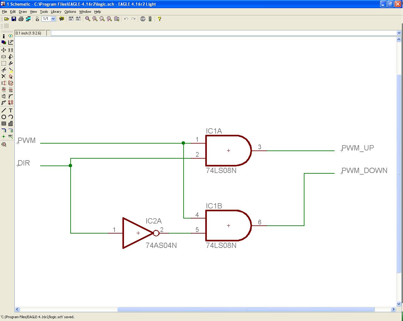
Couldn't you use this simple circuit.. (If I am understanding what you're trying to do)..
-
03-17-2008, 11:38 PM #5
Registered
- Join Date
- May 2003
- Posts
- 42
Hi Samco
Thanks for your input.
I am hoping it is as simple as you have drawn, but I must admit I am a little confused with this whole pwm thing. I thought that I needed a pwm signal that at 50% was zero speed and then anything above 50% the motor spun CW, and anything under 50% it spun CCW. Doesn't the circuit that you have shown still give 100% pwm for FWD and for REV? Are you using this circuit on your drives? or does your controller put out the pwm and not pwm signals?
As I said before I really don't know, and I am worried about the big puff of smoke.
Thanks for your help.
Regards
Andrew
-
03-18-2008, 01:22 PM #6
Gold Member
- Join Date
- May 2006
- Posts
- 2420
I think Samco's circuit would work, I have been thinking of this problem and arrived at the same result as Samco.
This would still fire the 2184's in sign-magnitude mode (I think) but that is still OK, and it is nice and simple, if the (top) 2184 has an input low (dir0 in the above schem) then it fires and holds the low side gate, the dir signal is inverted then "AND"ed with the PWM to fire the high side gate on the opposite half bridge 2184, so the servo will spin in one direction with magnitude according to the PWM. With the input high (dir1 in above schem) the high side gate is fired, the inverted signal goes to the opposite half bridge which fires the low side gate, hence the servo spins in the other direction according to the PWM again.
Both half bridges still see a PWM signal as the DIR is "AND"d with the PWM input so this will still give some dead time on the high side to charge the bootstraps.
It isn't locked anti phase as such but still sign magnitude, but will work on the same h-bridge that accepts PWM and NOT PWM input.
I hope I read this right as now my head hurts...
The circuit is devilishly simple but effective, nice work Sam !
Russell.
-
03-18-2008, 04:39 PM #7
Registered
- Join Date
- Feb 2008
- Posts
- 33
Yeah the 50% PWM is called "locked antiphase" control. It will give better control of the motor near 0 speed but you don't need it. The downside is that depending on your motor inductance it can cause the motor to heat up just sitting still.
Use the circuit provided by samco on the upper bridge drivers and then use the direction signal on the lower drivers.

 Reply With Quote
Similar Threads
-
DR SIGNAL OFF
By mustafaguler in forum FanucReplies: 0Last Post: 02-22-2008, 07:46 AM -
DR SIGNAL OFF
By mustafaguler in forum FanucReplies: 1Last Post: 02-16-2008, 05:26 AM
