


Hi all,
I'm new to this forum, I am a final year student and my final year project is to take an old Hercus v300 Compumill and rip out it's electronics and replace them so that it can become operational again. I am totally new to this and I would appreciate any help.
So far I have seen a previous article here about a Hercus CNC v300 Compumill, however it was quite limited and so is the manual I have. If anyone knows where I can get a service manual or something that can tell me a little more about the circuits and drives that I'm dealing with I would really appreciate it.
The ANCA 2000 board that contains all the high level electronics has had coolant leaked onto it and after storage in a shed for several years it's become significantly damaged. This is the reason that we acquired the machine without a hefty price. The drives and spindle and mechanical parts (as far as I've been told) are in perfect working order, it's just the electronics that are screwed up. My project supervisor and I quickly decided that the best option would to replace the ANCA 2000 board with some newer electronics.
I'm now at the stage of trying to access the motor drives and the resolvers to try and figure out a little more about how the machine works.
I'll be doing that tomorrow, I'll keep everyone (which is basically myself so far) posted.
PS: Does anyone know anything about how to make polycarbonate safety covers??? (Yes, I know, I really have jumped in the deep end with this project... )
Thanks.
Results 1 to 16 of 16
-
03-25-2008, 06:48 PM #1
 Registered
- Join Date
- Mar 2008
- Posts
- 2
Resurrection of a Hercus v300 Compumill
-
06-30-2008, 07:14 AM #2
Registered
- Join Date
- Dec 2006
- Posts
- 4
Sorry about the late reply...
Howdy:
I do search this site for Hercus comments from time to time. I must have missed your question.
I revived a Hercus V300 mill and I am working on the lathe too.
Back in 2005--or about then--I found the DeskCNC system at IMSERVICE and took a chance on getting it to run something as large as the Hercus mill.
It works great. I bought the fully assembled controller and got the mill working in a few weeks.
I installed the Globe motors that IMSERVICE supply and that was very easy. I feared that I would need to hand machine some adapters; however the motors were almost a direct replacement for the Hercus servos. The mounting screws, motor collar, and drive shafts are English units. The four bolt hole are placed identically to the holes on the original servos. All I had to do was use the English unit screws that came with the motors. The motor collar is 1 inch diameter, 25.4 mm, so it wouldn't fit in the Hercus mounts. A rough file took care of that in a few minutes--you can either file the motors mounts larger or file the motor collar smaller. Finally, I drilled out the pulley for the belt drive so that it fit on a 0.250 inch (6.35 mm) motor shaft instead of the 6 mm motor shaft.
I removed and stored the original servos and encoders. I plan to use them with DeskCNC and Gecko drives to bring the machine back up to full power some day. If I knew enough back then, I would have done that from the start.
The globe motors have the encoders on the motor. I often think of mounting them on the roller screw like Hercus did; I have not tried it.
I did not need the gear reducers on X and Y axis. I installed the reducer on the Z axis because I was getting faults during my tests. I bought a 4 axis system and I did not install the 4th motor/encoder. That would cause random faults that I believed to be the Z drive stalling while raising the heavy spindle. By the time I realized that random noise on the 4th axis encoder input was to blame, I already had the Z axis driven by the gear reducer.
We've run the machine hard for three years now will little trouble. I will be glad to finish the lathe. I bought the kit instead of the prebuilt controller to save some money and I haven't finished the upgrade in two years. I hope to work on it this August.
The old controllers are not worth bothering with--although you might sell them on ebay. A lot has changed in the last 20 years.
The machine is doing well, but I need to adjust the satellite roller screws. Many years of use by students brought in too much backlash. I found the original supplier for the screws. If I could find the screw numbers, it is possible to adjust a spacer and reduce the backlash. However, my roller screws do not have the part number engraved on them. Some satellite roller screws need a thicker spacer and other designs need thinner spacers to control the backlash.
Perhaps you've finished your project by now. If so, I hope that it went well.
Regards.
-
11-01-2008, 09:28 AM #3
Registered
- Join Date
- Mar 2008
- Posts
- 2
Sorry about the late re-reply...
I gave up checking this forum a long time ago. But I just took a look back a few days ago and unfortunately, my project is over now...
I made custom circuits and had them etched. The only thing that remains is to see if they work.
The project is by no means even close to completion. There are a lot of aspects to the project that I didn't mention before... anyway...
I'll try keep this thread up to date in case anyone in future wants to look at it.
Thanks for the reply anyway.
Regards.
-
09-21-2009, 01:53 AM #4
Registered
- Join Date
- Jan 2009
- Posts
- 14
Hercus cnc
Hi,
If you are still reading this service would you please contact me
off line. Mail, [email protected]
Thanks,
Doug
-
10-14-2010, 07:52 AM #5
Registered
- Join Date
- Oct 2010
- Posts
- 0
Project update
Hi all,
I'm not sure if anyone reads this post still, but here goes...
I just found this post, I am a final year project student continuing the work described in the initial post. The previous student designed a custom control solution with seperate microcontrollers for each axis X,Y,Z. The 3 axes are synchronised using a master controller, which is also powered by an Atmel AVR microcontroller.
I am near the end of my project; so far I have wired up and tested all the boards and I am close to getting the machine working. My thesis is due soon, so I think I will provide a more detailed post once I am finished.
If anyone is still interested, please don't hesitate to reply to this post.
Thanks!
Mat
-
10-16-2010, 02:48 AM #6
Registered
- Join Date
- Oct 2009
- Posts
- 45
Hi,
Last year I had a quick look at the thesis posted at UWA (cant find it now, the link is broken). Quite an involved project as I recall, re-creating a new control electronics etc...
I also have one of these V300 mills which was completely dismembered by the previous owner..! Does anyone have a pdf copy of the maintenance manuals for the mill, Hercus no longer supports these machines.
I'd like to be able to use the original spindle drive (I have several drives in working, near new condition), but have no idea how it was hooked up. I know on the Compulathe it has a resolver coupled to the spindle which provides both feedback & index position for threading... but I cannot see any location where the resolver would be attached on the mill's spindle...? Any ideas - pictures would be very helpful. I am hoping that if I can hook it up correctly I'll be able to program and run a tapping cycle.
p.s. my Compulathe is in original condition and still running with the Hercus/ ANCA control... quite remarkable for 25 year old technology.
Dan
-
10-16-2010, 09:07 AM #7
Registered
- Join Date
- Oct 2010
- Posts
- 0
I have only briefly had the spindle running, as far as I know it does not have any feedback. The original control interface for the spindle only has 3 operating modes: Forwards, reverse, and stop. There is also a spindle speed override knob to limit the speed.
I will be applying an optically isolated PWM signal to the spindle motor to turn it at (roughly) the desired speed. I think the original student may have intended to retrofit a rotary encoder in order to get some sort of feedback from the spindle, but I haven't looked into this.
On this machine the spindle power wire has been extended with what I guess is a bit of an old AC extension cord so I don't really have much more information about how it is meant to be connected normally. I have cut back to the original wires and there are: 2 black wires (labelled '1' and '2'); and a green/yellow wire which I assume is an earth. I will try to get it going and report back later. The motor is a DC permanent magnet motor rated to up to 180V.
As for the manual, we only have a print copy in a 3-ring binder that I try not to touch too often (some of the pages and are starting to fall out). It might be worth getting the manual scanned at some point (though it is about 500 pages long). So far I haven't found anything about the insides of the machine and the wiring, it seems the Hercus was never intended to be opened.
It does say that the high speed configuration (which I am using) goes up to 3000RPM while using the low speed pulleys will give about 1100RPM.
-
10-16-2010, 02:14 PM #8
Registered
- Join Date
- Oct 2009
- Posts
- 45
Both the Compulathe and V300 mill share the same DC motor and analogue drive components, but if the mill does not use a resolver I wonder how the drive works without any sort of feedback.
I have all the manuals for the lathe but not the mill. The maintenance manual is fairly detailed with crude diagrams. These machines were known to break down alot and required a lot of self diagnosis and repair. The school that I got mine from sold them after only a few years of use because they spent more time repairing them than using them to teach the cnc course.
-
10-18-2010, 03:50 AM #9
Registered
- Join Date
- Oct 2010
- Posts
- 0
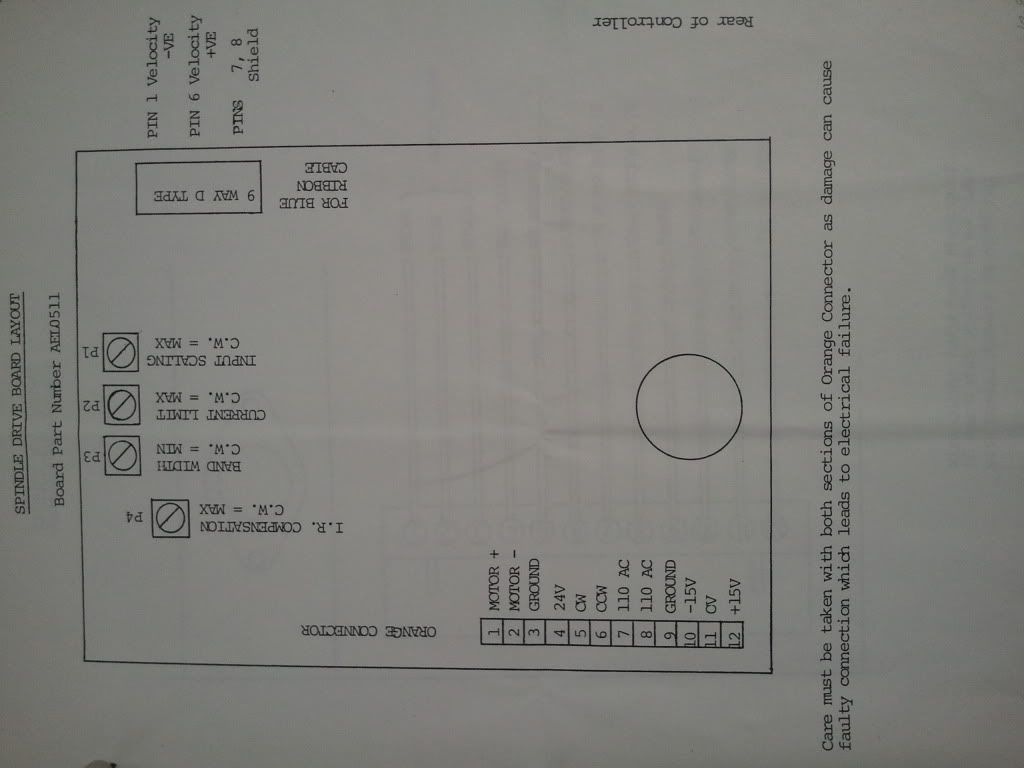
I have read a bit more through the manual:
- the spindle operates via feed-forward control
- the spindle board is located next to the transformer and has
4 trimpots which are used to tune the motor current
-while tuning, an external device must be connected to measure
the angular velocity (RPM) and an ammeter must be connected
in series to measure the current
-once tuned, the motor RPM should be capable of acheiving a set
speed +-5%
The trimpots P1 (fine) and P4 (coarse) are used to tune the current. P2 is used to adjust the current limit which is apparently found by setting the spindle to 500RPM while holding it to stall the motor.
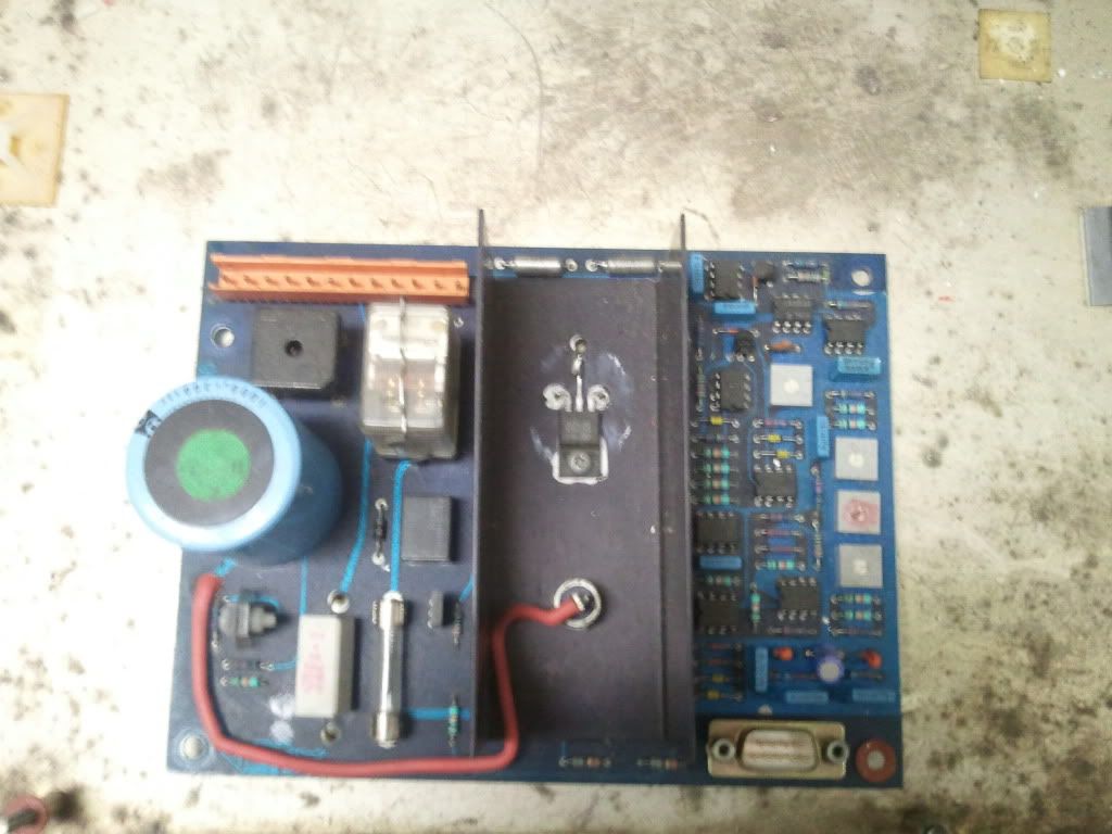
I have tried to attach some pics. Sorry about the size, its my native phone resolution.
-Mat
-
07-24-2011, 10:07 AM #10
Registered
- Join Date
- Feb 2008
- Posts
- 33
Hi Guys,
Hadn't noticed this post before, hope it's not too long gone, but I've replied to a few recently and hoped it may assist others searching for help on Hercus machines or anything with ANCA controls.
The ANCA controls are still fully supported, though there seems to be a lot of people who weren't aware of this. For service, parts and support you should contact Ultra Logic Systems Ultra Logic Systems - Home who handle the service for the ANCA controls.
If they are setup and serviced properly, then the ANCA's can be very reliable, unfortunately in the past some of the people working on them didn't know enough about them to do the job properly (or people may have attempted it themselves, often being in academic environments) and so some people have bad experiences. It's a pity, as the Hercus/ANCA are still to this day a great little machine and very capable if setup and serviced properly.
The spindle board pictured by Maximushki has been 'modified' by somebody and does not have all original parts - perhaps supporting what I wrote above. The board pictured is the early version known as the '200B' and there was a number of revisions after this, the later 200C Rev II and Rev III (IIRC) having an extra pin towards the right hand side of the connector (not shown on the overlay diagram in this post).
The spindles are fully variable speed, not just Fwd/Rev/Stop as was suggested earlier. An S-code is used to set the spindle speed and the usual M3/M4 (eg. S1000M3). The spindle drive gets feedback from an I/R circuit that monitors motor current. On the lathes (and some mills IIRC) the resolver also provides a second feedback loop via the control and it's velocity command. P1 was the Input Scaling, not the current control and from memory the P2 Pot was factory set and shouldn't be adjusted. There was a number of errors in the Hercus Manuals, so it may not always be correct. The main control board (Single Board) was usually a cut-down version of ANCA's industrial board (typically Rev B or Rev C) and the servo and spindle drives I believe were more made to a price, rather than for outright reliability, as they were aimed at school environments where there was a more limited budget. That being said, if they are setup properly and current level modifications added, they are quite capable and many these days are happily working in original form on a daily basis in industrial situations. There was a number of different models and versions of both servo and spindle over the years too. There was various options with Turrets (this was also an option on later model mills) and some even had air-chuck and coolant, although the coolant option was only really successful after Hercus finally moved the control to the back, instead of underneath - even then it was rarely fitted.
Anyway, perhaps this info might be of use to somebody.
Cheers,
Grant
-
07-27-2011, 04:01 AM #11
Registered
- Join Date
- Oct 2009
- Posts
- 45
Hi Grant, thanks for the info.
As mentioned in my earlier post, the previous owner of my Hercus V300 Mill removed all the electronics and threw it all out many years ago in a failed attempt to turn it into a manual mill ...Hence my attempt to retro-fit a new control (geckodrives & DynoMotion), but I did plan on using one of the original spindle drives which I DO have.
As it happens, I also have a Hercus Compulathe which is completely original - 1986 deluxe model s/n 6W-50 with 8 position turret & pneumatic chuck. This machine is still fully functioning with the ANCA control and CTURN-13A software. With it, I also have many spares as backup... 4 spare spindle drives (200B rev orig., rev. 0 & rev. 1) as well as several axis drives an 2 spare singleboards... However, the spare singleboards will not boot up, and most of the drives have burnt traces where the bridge-rectifiers attach.
The lathe is not without issues though; as you have eluded to, the cable glands where the wires enter the electronics cabinet under the bed of the lathe allow way-lube to seep through and this drips onto the singleboard causing the servos to jitter and lurch into alarm mode. Someday I hope to relocate the cabinet behind the machine to alieviate this problem. I Have also recently had the air valve that operates the chuck fail, I believe the seals on the sliding piston within the valve have swollen and siezed up...
I am aware that the spindle control is more than fwd/stop/rev, as I usually run in feed per rev mode... very cool to see constant SFM mode in operation.
Cheers,
Dan
-
07-27-2011, 12:37 PM #12
Registered
- Join Date
- Feb 2008
- Posts
- 33
Hi Dan,
Didn't realise you had the mill and no electronics.
As you may realise, the Servos and Spindle drives on these units use Industry standard +/- 10V Velocity Commands, but most of the hobby stuff uses Step/Direction. You might be able to grab a converter if you are inclined to go that way. IIRC the Spindle just uses the 0-10 part of the +/- and the CW/CCW signals set the dir. The motor won't reverse until the circuit senses it's at zero speed (or very close).
If you have spare Single Boards they can be fixed no problems, they might seem a bit behind the times, but they do have some pretty fancy features for their day and are pretty decent *if* done properly. Do be careful of battery leaks though, this is the single biggest issue with these boards, because people let them deteriorate. Look at the blue soldermask around within about 5inches radius of the battery - if you see any slightly darker areas under the blue mask, that's electrolytic corrosion and needs to be fixed properly before it gets worse. Likewise any salty looking buildup or green tinges. If you come across this, I don't recommend you attempt this yourself, unless it's cut out properly and properly treated, it will just continue to grow under solder, masks, etc and will destroy the board.
Yep, the rectifiers are a common issue and when they go it usually takes out a bunch of stuff on the DC side also (as you've no doubt discovered). There's quite a lot of modifications that have been done over the years and certainly that particular problem has been eliminated completely (with latest mods), along with various others. If you have oil/goop soaked boards and want them cleaned, Ultra Logic do have a process that will get them spotless.
On the Computurn, If you are getting oil down in the cabinet, there are two potential areas, one is the cable gland area, as you've found, but it can also come through around the bolt under the Spindle Head - the latter can usually be fixed with a good quality sealant after removing the bolt, but it may be a leak in the spindle head, so check that out first. Always use a neutral sealant such as an automotive 'Sensor Safe' type. Obviously a leak will be a problem irrespective of what control or electronics you are using, so good to sort it.
Leaking around the cable glands usually means you're being a little too generous with the lube and it's building up in the base. IIRC the Lubrication Schedule calls for a specific synthetic grease on the Satellite screw (which incidentally is highly repeatable if in decent condition) and oil on the slides. You don't need a lot of oil and too much will build-up and leak around the gland. Sealing the gland is only half a solution, as the cables will still likely be sitting in oil and will deteriorate. Best to limit the oil if possible, or fix spindle leaks if they are the problem. I've seen rags used to good effect, as long as they are changed regularly and I've even seen kitty-litter used!
On the mill (Compumill), keep an eye on the counterweight (actually springs in the column) cable and ensure you lube the pulleys. The cables can deteriorate and break and likewise the spring. Often this goes unnoticed and ends up burning out a drive or motor if pushed enough.
Yep CSS is pretty cool, hearing the spindle whiz up and down as the tool gets closer and further out, but those controls had a lot of very cool features and are highly underrated. Try G60 Splining and I think you'll like it. Heaps of other fancy tricks under the hood.
Cheers,
Grant
-
07-27-2011, 11:59 PM #13
Registered
- Join Date
- Oct 2009
- Posts
- 45
Hey Grant,
A number of years back, I missed out on a huge opportunity to grab a bunch of spares. The guy who got the majority of the machines & spare parts from the trade school auction threw out a trailer load of machines and parts ...! I called him out of the blue for some parts I knew he had from a previous visit, but about a couple months too late... Otherwise I would have driven the 2000km with my trailer in tow to collect his "garbage"...and would've rebuilt my mill back to OEM spec. Oh well, Too bad!
You mention that the later revisions of the drives were improved... can the the old ones be upgraded? I know the latest rev spindle drive that I have (rev 1) has a much larger rectifier, but it has already been blown. I still have a couple good drives for both spindle & axis.
Cheers,
Dan
-
07-28-2011, 01:21 PM #14
Registered
- Join Date
- Feb 2008
- Posts
- 33
Hi Dan,
'Missed it by that much' eh? D'OH!
Re. modifying the drives, it depends on the drive to some extent. Some can have some improvements added, others can have other / additional ones. It's not just bigger rectifiers of course, that's just one part of things. In general terms it is usually possible to get good improvements to the older model Axis and Spindle drives to. It's also possible to add the extra Enable line to the older (12 pin) model Spindles (along with an extra relay on the chassis). That will eliminate the potential for a brief 'kick' on start that some machines can get.
-
05-24-2012, 01:24 PM #15
Registered
- Join Date
- Mar 2004
- Posts
- 9
Hi Grant,
on the subject of the ANCA Single board, do you know if there is a circuit diagram available?
The maintenance manual contains only details of the back up battery area but I am looking for information on the "start up " circuit.
Lex.Lex
-
07-03-2012, 06:21 AM #16
Registered
- Join Date
- Feb 2008
- Posts
- 33
Hi lsd0, Sorry I didn't see you post earlier. The diagrams for the board are not made available, but they can be repaired, etc. There's lots of little modifications over the years also, that you wouldn't be aware of. Best bet is to contact Ultra Logic Systems - Home and from there you can get all the help you need. The Hercus manuals only contain fairly superficial info, as Hercus didn't make the circuitry, just the machine. ANCA don't deal with those old boards anymore and Ultra Logic have officially handled all that stuff for many years.

 Reply With Quote
Similar Threads
-
Hercus V300 COMPUMILL DNC
By Jonathon in forum DNC Problems and SolutionsReplies: 4Last Post: 11-04-2008, 11:23 AM -
Compumill With Dynapath 20
By Cycle Start in forum Uncategorised MetalWorking MachinesReplies: 4Last Post: 05-31-2007, 06:43 PM -
Compumill retrofit
By Dick L. in forum Mach MillReplies: 4Last Post: 11-15-2006, 12:07 PM -
Fadal 4020 resurrection......
By jnc in forum FadalReplies: 12Last Post: 06-30-2004, 06:22 PM
