


It's possible that I may have in time what I think could be the nicest Enclosure for a Taig CNC. At least for melol. So you guys have probably seen my half built enclosure, black mortar tub with flood cooling. I was going too build a 8020 quick-frame design around it. Eh, but that may change, it just may change.
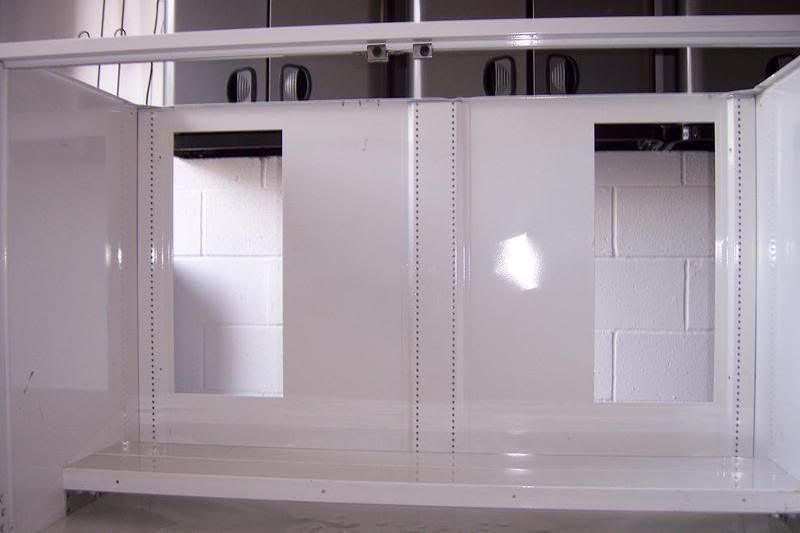
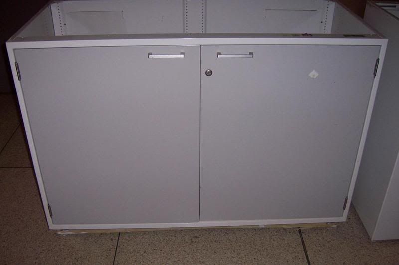
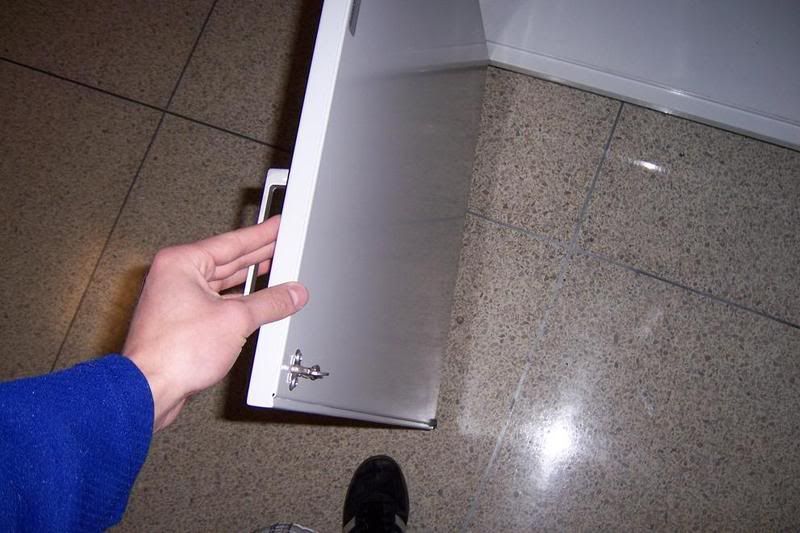
I go too school at New Jersey Institute of Technology as an MET and being the technical guy I am, I have this thing about "perfection" and symmetry relating too how parts work, how they are designed and put together etc. Well my school has some great things that are thrown out and I always pass by them and wonder the things I could do with them. For example, I saw this console station yesterday that had some screen in it, probably used in the electronics department and it could be cleaned up and used for A Mill Console, it was awesome! But anyway, I was passing my lecture hall and for the past 2 months, these Steel, white cabinets have been sitting outside the classroom with some junk Steel (heavy duty) open slot tubes; like so [ . I had the chance too look at it and starting getting ideas. I was thinking what a great enclosure this could be! I was excited.It has two nice thick doors with handles on top and is completely made of stainless steel. The cabinet measure I would say around: 35 inches in height, 50 + inches in width and 25-27 inches deep. I would have no problem with X axis travel and the Y axis should fit just fine.
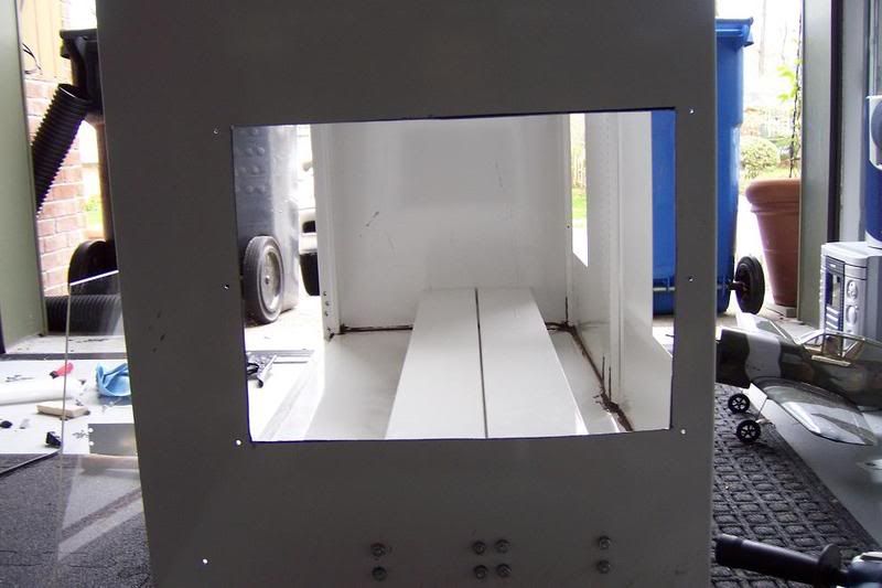
Before I get to the "drainage"/mounting Mill problem, some more things too talk about. The Back of the cabinets has two openings, around 6 inches wide and 14 inches in height. I would cover these with plexiglass and even though it's in the corner, it would still be awesome, cause I have spare plexiglass. On the side of the cabinet, I would like a window so I can see when I'm running it from my desk, I would now cut out a window, file and any edges and mount plexiglass. The Doors are thick, but not one piece, worst case scenario, I make new doors entirely out of plexiglass and mount them with hinges too the cabinet, I still want too make windows in the doors. We'll see.
Now the big question, how will you mount the mill and drain with a flimsy bottom. The cabinet floor is raised about 6 inches form the ground, so if you flip it over, it's a 6 in deep rectangle. My initial idea was too take steel and mount it directly to the back on the inside and on the side of the cabinet, Then i would take more steel and lay down a bed, making a "T" so the Taig could be bolt too the steel and have some rigidity. Again, this was my first idea and I don't know how well it will damper vibrations or cause them
Second Idea: I would on the inside of the cabinet start too form a bottom bowl with a mallet. I would beat the bottom of the cabinet floor from the "top", where the mill would be. I would do this until I got a large enough slant and bowl like affect. I would flip the cabinet over and fill the bottom 6 inches with concrete. The smashed in floor would act as a mold and when the concrete settles, it would shape up too be a bowl. I would... I think, need too seal the concrete and maybe smooth out the bowl. Having the cabinet flipped over now. I would mount two steel beams to lay on the concrete edges that would "gape" over the bowl; they would be mounted too the concrete. I could then design a drain system from there and the coolant, well, gravity would let it fall over the beams into my bowl and drain through filters. Once it is shaped and everything looked good, I would seal the concrete and seal all areas using caulk or some type of sealant.
It's sounds pretty complex but the idea is not so bad. The concrete would make for a great foundation.
-Jason
Results 1 to 20 of 39
-
04-16-2008, 03:27 PM #1
 Gold Member
- Join Date
- Sep 2006
- Posts
- 1738
 Maybe a New TAIG CNC Enclosure: Build Thread
-
04-16-2008, 04:15 PM #2
Gold Member
- Join Date
- Sep 2006
- Posts
- 1738
Actually, you guys are in luck, I forgot I have class lol. I'm going early, snapping pics of the "enclosure" and going too post them tonight!
-Jason
-
04-16-2008, 05:52 PM #3
Gold Member
- Join Date
- Sep 2006
- Posts
- 1738
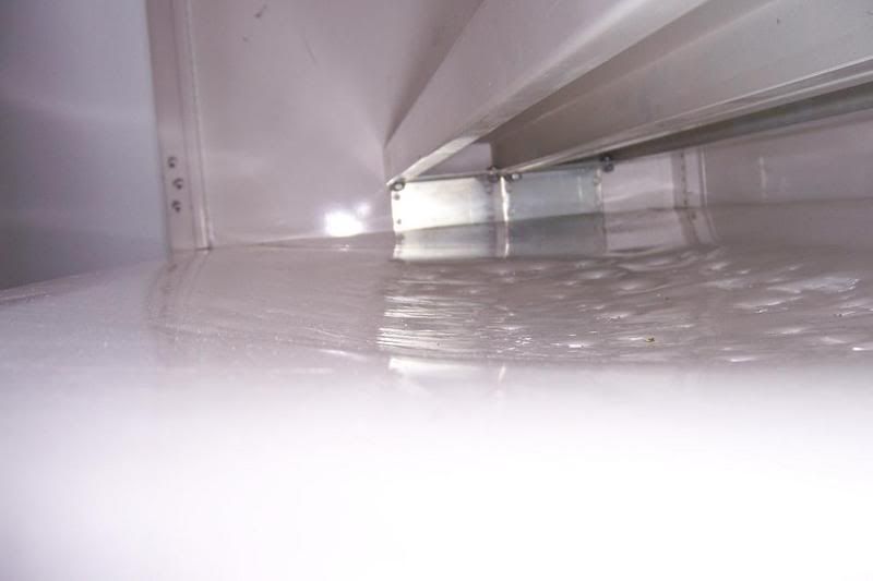
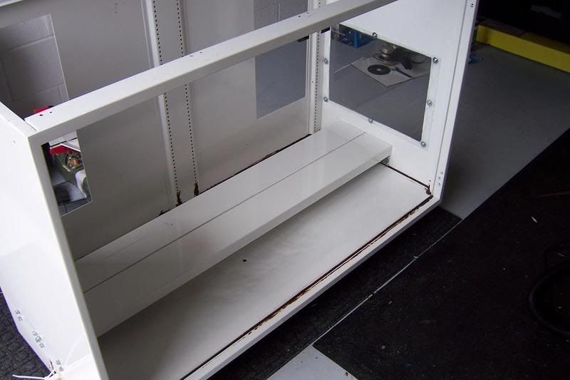
Just took pictures of it! Wow, it looks great. I will post tonight. Btw- The steel "C" tubes included have brackets on them. The first idea may actually not be so bad. It would now even be more simple too just shape the bottom for a bowl like affect and rest the Taig across the steal beams. it's interesting.
For even more stabilization I can drill right the back panel and mount too screws that will screw into the Taig frame: That way it can't wobble. This may just work!
-Jason
-
04-17-2008, 12:59 AM #4
Gold Member
- Join Date
- Sep 2006
- Posts
- 1738
This thing is rigid! I think I'm going too go with my first idea. Bottom will be beaten too a bowl. And those two steel cross beam you see will go across the bottom and mount too the side of each wall. The Mill will be bolted too the beams. Now your thinking about vibration and things right? Well, The Taig will be backed up with the to the end of the cabinet, standing flush and have two bolts running from behind the back of the cabinet into the Taig, that way it can't possible move left too right and it would have the support of the beams too. It's a perfect idea! The back will be drilled out so the Taig "Nut" holding the column can sit flush!
-Jason
-
04-17-2008, 02:00 AM #5
Registered
- Join Date
- Mar 2006
- Posts
- 304
Looks like a nice find - I like the 'cheap' surplus stuff. I got my control enclosure that way. My brother is an R&D engineer for a company and they had a couple 30x30x8 control enclosures laying around scrap - so with a wink and an after hours trip with the pickup I got a great enclosure that would sell for close to or more than 300 for gas money. Extremely oversize for my application (I could control a bridgeport, a lathe AND a benchtop with this thing) but lets me mount EVERYTHING in it so there's one cable to my X3, one to a monitor, 2 USB outlets and a PS2 Keyboard jack, along with every status LED I could come up with plus an a single power and E-Stop button.
Jason though - can you avoid posting in bold? My eyes aren't as crisp as they were in my younger years.
Every day is a learning process, whether you remember yesterday or not is the hard part.
www.distinctperspectives.com
-
04-17-2008, 04:06 AM #6
Gold Member
- Join Date
- Sep 2006
- Posts
- 1738
Yea, I love finding this kind of stuff, I have a very innovative mind and always find use for something (but I don't collect junk at all)
Sorry about the bold, I like the way it looks lol.
-Jason
-
04-17-2008, 04:10 AM #7
Registered
- Join Date
- Mar 2006
- Posts
- 304
Oh there's always a use for 'junk' - it runs in my family (you should've seen the two 20yd dumpsters we filled when my grandfather passed - paid for with the proceeds of scrap copper from the several hundred pounds of wire we carted out of his basement). I've got a small junk stash, but most of it is either small (salvaged electronic components) or I have visions for future use.
Good find though.
Every day is a learning process, whether you remember yesterday or not is the hard part.
www.distinctperspectives.com
-
04-17-2008, 04:13 AM #8
Gold Member
- Join Date
- Sep 2006
- Posts
- 1738
There throwing like 4 out, I'm also taking more of the steel beams and putting them in the cabinet, SHHHH lol.
It will be in the shop tomorrow!
-Jason
-
04-17-2008, 11:08 PM #9
Gold Member
- Join Date
- Sep 2006
- Posts
- 1738

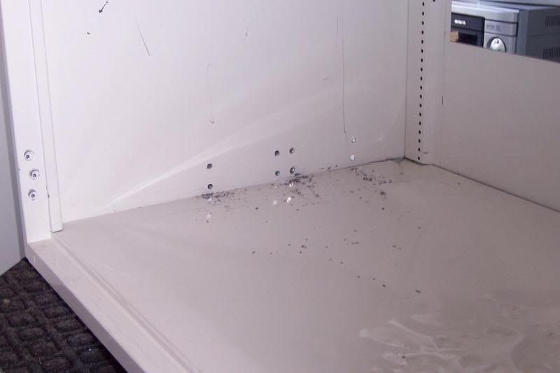
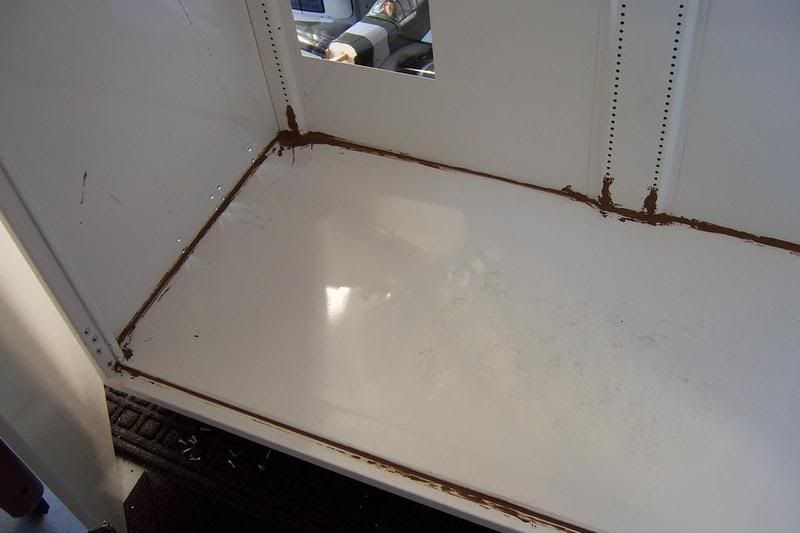
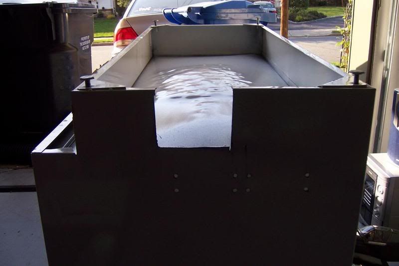
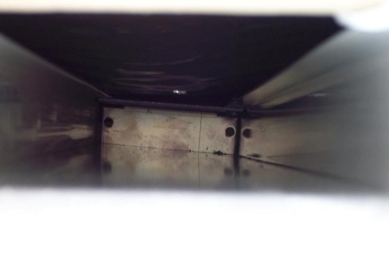
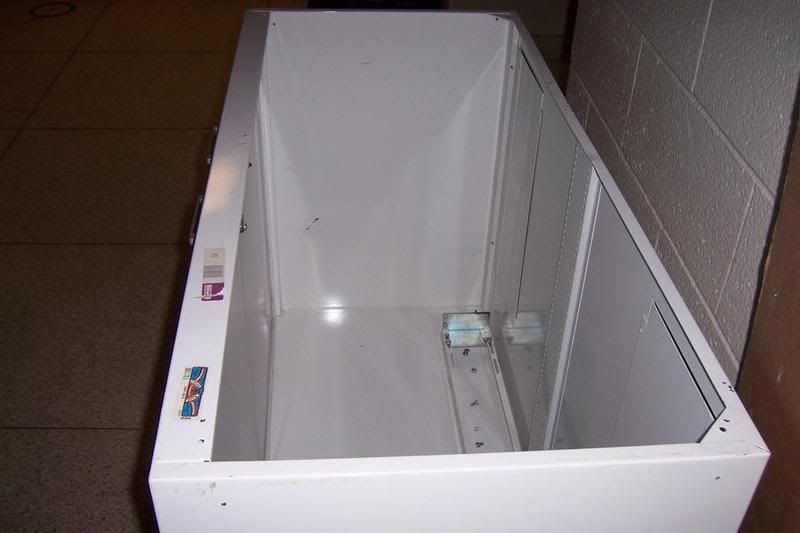
Check out pics from today! I picked it up and took a bunch of the steel beams. So people get a better idea of what I was talking about, look at the first picture. The Mill will be bolted too that and the coolant will fall and drain. It looks really awesome and should be great. I sealed it and should dry in 24 hours. Wish it was white, but I was impatient, Oh well...It's going too look great. The Mill is just going too barely fit on the "Y" axis, I took a estimation of the depth and was wrong. But I'll make it work!
Enjoy!
Look how awesome thats looks!
Please comment or discuss
-
04-18-2008, 12:18 PM #10
Registered
- Join Date
- Mar 2006
- Posts
- 304
Looks great - well suited for the Taig. I'd even consider making some simple baffles for the back openings using them for fresh air intake/exhaust and then covering the top with acrylic and an access door for adjustments to cut down on the noise.
Every day is a learning process, whether you remember yesterday or not is the hard part.
www.distinctperspectives.com
-
04-18-2008, 02:03 PM #11
Gold Member
- Join Date
- Sep 2006
- Posts
- 1738
I plan on covering the top yes. I will make some exhaust vents in the back and probably the top. I really like the way it's coming out.
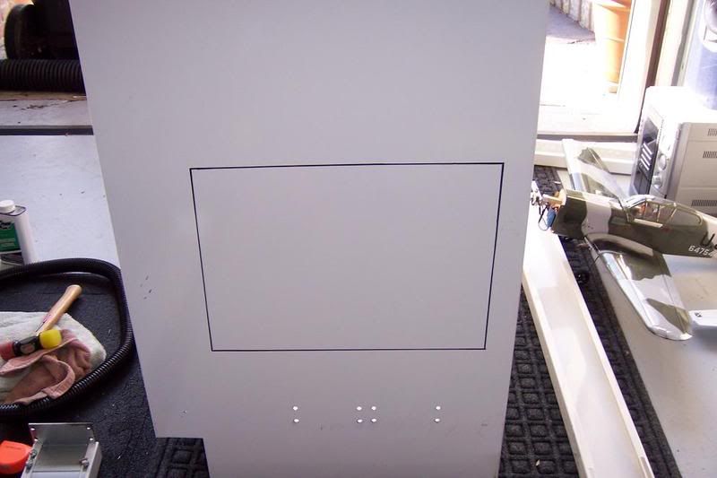
I'm in a dilemma, I want too make a cut in the side so I can place a window. I don't know what kind of tool too use. The Stainless steel is about 2.60mm (But thats with paint too) So I don't know if I should an "Air Cut-off saw"-18,000 RPM like you see on American Chopper or a Metal Shear with like 2500 strokes a minute. It's a 20.00 difference and more for the shears. But the Shears will only cut 3/64" steel; but thats steel, not stainless steel. I need help on that.
-Jason
-
04-18-2008, 02:25 PM #12
Registered
- Join Date
- Mar 2006
- Posts
- 304
My experience would be if you are screw mounting your plexi/acrylic windows, cut a plywood piece as a backer about 1/16" oversize, bolt it on the backside and then use a jig saw and some cutting fluid in a spray bottle. If your jig saw can handle the depth go for a front and back support to the exact size of the cutout. If not cover the saved side (good piece, finished surface) with some thick mylar packing tape to avoid scratching with the chips.
Other option that worked well for stainless fab when I was in the restaurant biz was an angle grinder with a thin cutoff wheel, just watch heat so you don't warp and/or oxidize the SS. We didn't worry too much since we were tig welding and weren't able to back side purge the weld anyway so as long as we could dress the exposed seam it was adeqaute for health dept regs.
I just cut the 4.25" diam vent hole for my driver assembly in the 0.187" steel backplane last night with a jig saw, 18tpi blade (for your SS I'd use a 24tpi) and a hand sprayer to semiflood the cutter. I didn't need any backsupport since it was 2x your thickness. Very nice cut and followed the circle I scribed almost to a T - scuffed the paint up pretty good around it but it's not a visible component so I'm not concerned. If you have an assistant handy having them spray while you cut would be a lot easier.
The shears won't cut it - 2.6mm = .1023" -> 3/64" = .0468" - nearly 3x the capacity on a stiffer material. I doubt it'd make one stroke and if it did you'd probably go through several cutter heads.Every day is a learning process, whether you remember yesterday or not is the hard part.
www.distinctperspectives.com
-
04-18-2008, 03:29 PM #13
Registered
- Join Date
- Jan 2007
- Posts
- 525
Speeds -
Can you add a few pictures of where your enclosure will end up? Seeing the room and table/bench would be great!
CheersTormach PCNC 1100, SprutCAM, Alibre CAD
-
04-18-2008, 04:12 PM #14
Gold Member
- Join Date
- Sep 2006
- Posts
- 1738
Cadmonkey- I was thinking of buying a Cut Off wheel, I know the sheers cutting size was too thin, I caculated last night. I think a Cut Off Wheel would do wonders and I'll also pick up a 24tpi blade for my jig. I'm pretty sure the Cut off Wheel would be better, but let me see what happens. I'll try both and if doing to jig, I'll use your idea with the wood and stuff.
Tikka, will do
I also have an amazing Idea for filter Should be cool.
Nice too see people responding too the thread!
-Jason
-
04-18-2008, 06:51 PM #15
Gold Member
- Join Date
- Sep 2006
- Posts
- 1738
Ideas for the drain are all set. The bottom of the cabinet will be lined with 2x4 's, 48 inch across on both sides and one piece just off of the middle point. My drain system is pretty snazzy:rainfro:. A smaller steel beam will have a hinge on one end and will be attached too the "cross" 2x4 with a height as much as it can go until it hits the concaved bottom. The beam will run down at an angle out one of the side panels. At the end of the beam my Humidifier "filters" will lay flat across and be slightly compressed by a piece of aluminum or wood making the filter even harder too let any chips through. This idea opposed too say, the chips and coolant falling right over it; only have too travel an inch of filtration. By laying down the filter and the chips coming from the side, they will have too travel over 9 inches too get through, if they even do get through. The coolant will have no problem getting through. At the end of the table will be some galvanized metal (Pre-shaped) for laundry exhaust for homes etc...It will run down into another bin yadada, this part is not important. Clean will be a breeze! When the chip gather up before the filter, easy access at hip waste with a vacuum cleaner! It's going too be superb
A quick drawing made in school! ahahahahaha
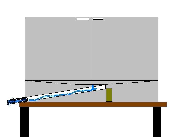
-Jason
-
04-19-2008, 12:36 AM #16
Gold Member
- Join Date
- Sep 2006
- Posts
- 1738
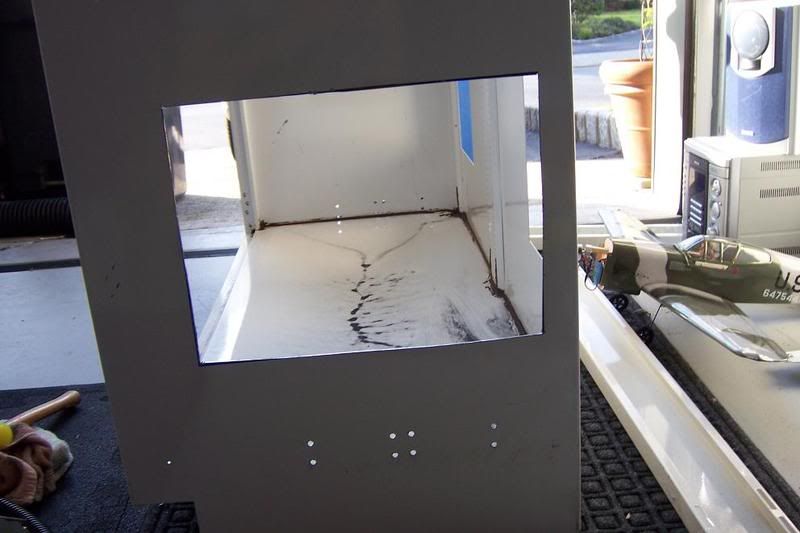
What a success!
Went too Home Depot, got some supplies...but more importantly, got the tool I needed. The cut off wheel, I took a metal cutter, thinner than the one supplied; knowing it would work I went ahead and started working. Question was, how long would it take? Lets just say it was fast
Cuts like butter! Actually one of my favorite tools now total window time for cutting: 10 minutes :rainfro:
It's starting too look real good and the hardest part is done. The window (nuts)
-
04-20-2008, 04:52 AM #17
Gold Member
- Join Date
- Sep 2006
- Posts
- 1738
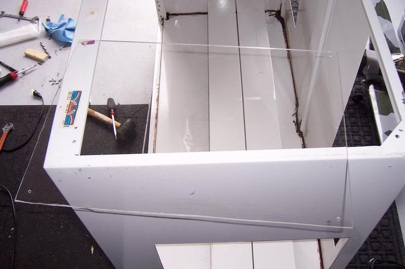
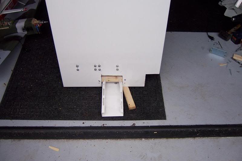
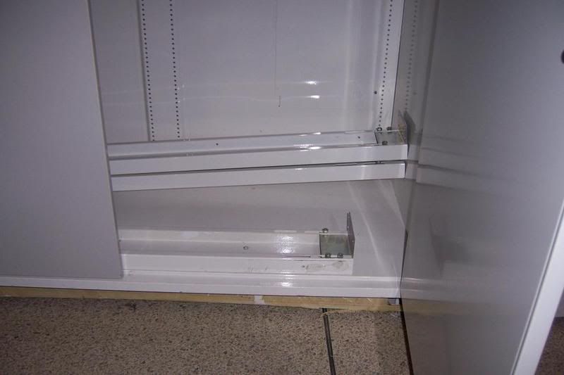
I got the bottom of the enclosure forced up with 2x3's just the way I wanted and mounted my tilted drain pan. Looks good, Will attach the plexiglass and the taig too the beams and I should be ready too roll soon. Still not done, don't want too rush it though.
-Jason
-
04-20-2008, 05:09 PM #18
Gold Member
- Join Date
- Sep 2006
- Posts
- 1738
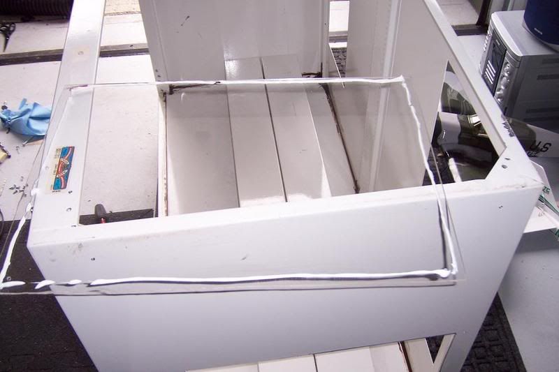
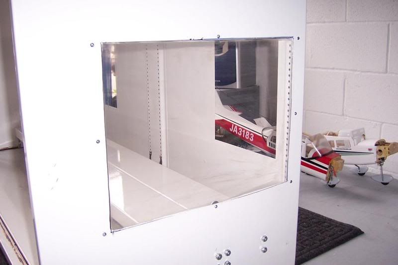
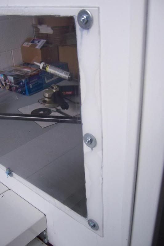
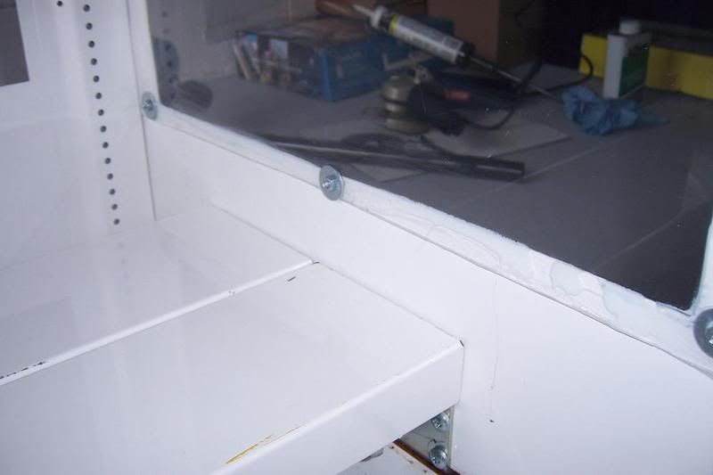
Another good morning of good work :banana: I installed both cross beams, everything bolted and got my window done and sealed. There is still some good amount of work too be done; I still need too mount the flanged aluminum on the doors so when coolant sprays it will drip down the door and slide down aluminum, this will hopefully prevent any leaks. I'm still designing though. I also think i'm just going too mount the back panels again instead of windows. It's kind of stupid since it's in a corner. Once all the hard stuff is done, I'm going too make the outside look good. There have been a few scratches, dings etc. Just going too make it look better and add some nice Stickers!
ENJOY!
-Jason
-
04-20-2008, 05:21 PM #19
Registered
- Join Date
- Jan 2007
- Posts
- 525
Looking good!!
Tormach PCNC 1100, SprutCAM, Alibre CAD
-
04-20-2008, 05:33 PM #20
Registered
- Join Date
- Nov 2007
- Posts
- 980
Indeed, it's looking great and you're definitely inspiring me!
Dave->..


 Reply With Quote
Similar Threads
-
My TAIG enclosure is here!
By Smertrios in forum Taig Mills / LathesReplies: 18Last Post: 08-16-2016, 01:15 AM -
My new Taig Enclosure using 80/20
By L2A3 in forum 80/20 TSLOTS / Other Aluminum Framing SystemsReplies: 19Last Post: 11-21-2010, 03:45 PM -
Taig Drainage/Coolant System-Enclosure Build~ Pictures~Video~!
By CROSSHATCH in forum Taig Mills / LathesReplies: 25Last Post: 01-16-2008, 12:58 AM -
80/20 TAIG CNC Mill Enclosure
By tikka308 in forum Taig Mills / LathesReplies: 17Last Post: 12-06-2007, 11:43 AM -
Taig Enclosure Overkill
By pdxalz in forum Taig Mills / LathesReplies: 8Last Post: 09-19-2007, 11:38 AM
