


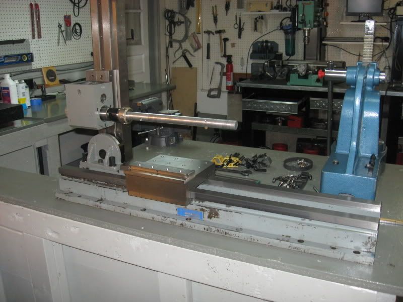
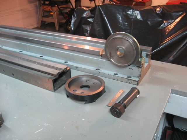
This machine buildup begins with a very nice heavy duty 36" long 200lb Gilman/SKF box way slide that was shown and discussed at the end of this thread-
http://www.cnczone.com/forums/showth...=40584&page=21
The vertical dovetail slide for the milling head is from a x2 mini mill.
The mill column is on a pivot. I'll be machining a custom dovetail mount for the mill head that will also be on a pivot to fit the vertical dovetail column. This will allow the column to pivot as well as the milling head and will allow many options.
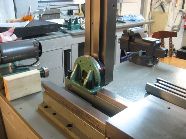
The vertical column is mounted with 2" deep threaded studs and a central through bolt and nut clamp into the gilman slide Iron base. I had to cut out a portion the very hard slideway. The meehanite iron base of the slide machines wonderfully.
So it's a start.
Just about the limit for my x3 mill-
vertical column mount parts breakdown-
assembled and mounted-
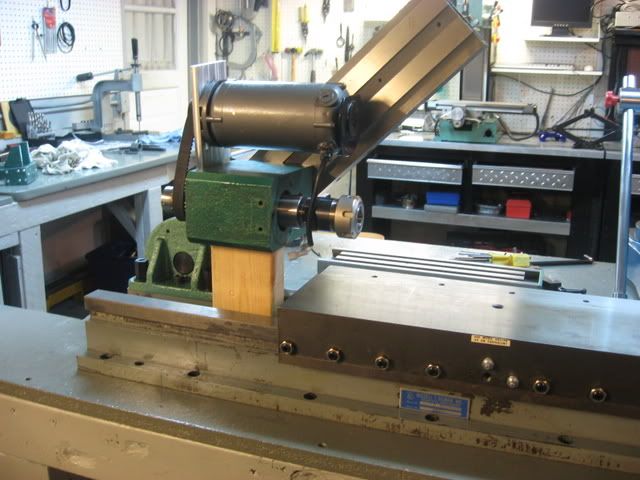
mill head mockup on column-
With the column angled and the head on a pivot, many possibilities and carriage table could pass under milling head.-
Wood block is just supporting the head right now to show it will be positioned on the column eventually as there is nothing yet to attach it to the dovetailed column.
Steve
Results 1 to 20 of 52
-
07-20-2008, 12:00 AM #1
 Registered
- Join Date
- Mar 2006
- Posts
- 357
 A horizontal boring/mill machine build
-
07-20-2008, 04:07 PM #2
Registered
- Join Date
- Mar 2006
- Posts
- 357
I want to explain just a little bit more about this project as I think it may not be readily apparent just what the heck it is I am building
 . This machine will be able to do things my mill and lathes can not, or would not be able to do as well.
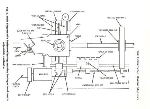
The horizontal boring mill is used mainly for work that has a diameter or width greater than it's length.
It will be able to line bore, drill, horizontally mill and even turn.
This is a basic schematic of a small horizontal boring mill-
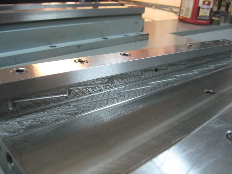
The Gilman slide I am using for the z-axis is very well made. Very rigid.
Note the wonderful scraped box ways and coated gib with oil routes-

The machine I am loosely patterning this build after is based on this small old horizontal bore mill which another member posted a link to in his buildup of a horizontal mill -
It will have table powerfeed.
Steve
-
07-21-2008, 12:10 AM #3
Registered
- Join Date
- Mar 2006
- Posts
- 357
I accomplished quite a bit today.
Disassembled the mill head. I will replaced the cheapy deep groove bearings with better tapered rollers.
I remembered Hoss and his freak x2 machine where he mounted a Zaxis mini mill column to replace the standard x-axis table. Well I just so happened to have the dovetail unit for the x-axis and low and behold, a perfect fit to the z-axis column. Just a matter of machining off the dovetails used for the Yaxis and flycutting a flat surface to mount the mill head on. The mill head was flycut as well. Some time spent with both on the surface plate shows me I have a little scraping to do but nothing major. I'm sh!t canning the idea of a pivot head.
I'll take some new pics in a few days.
Steve
-
07-27-2008, 12:19 AM #4
Registered
- Join Date
- Mar 2006
- Posts
- 357
I think I hear crickets in this thread....
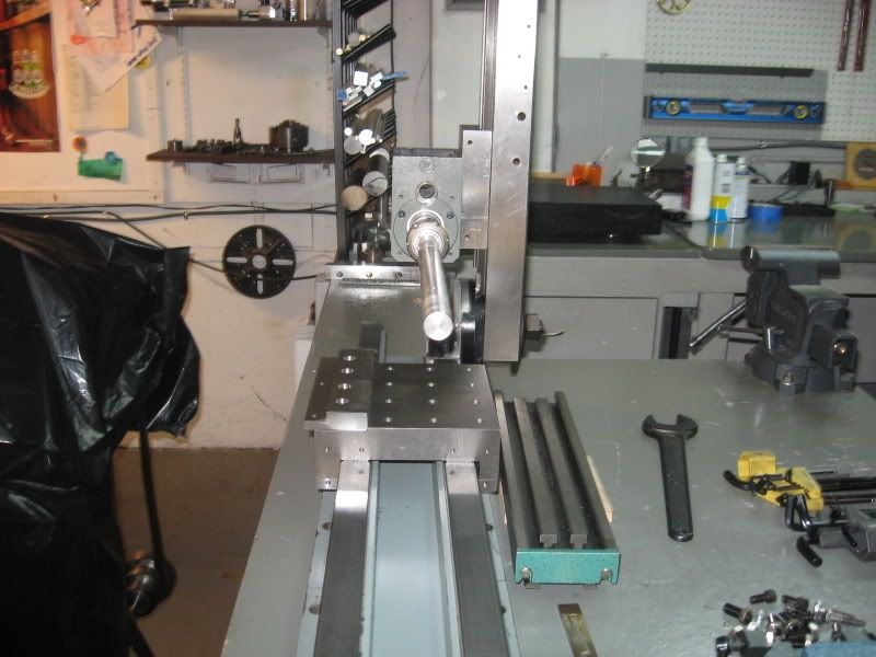
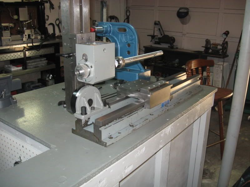
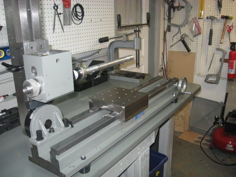
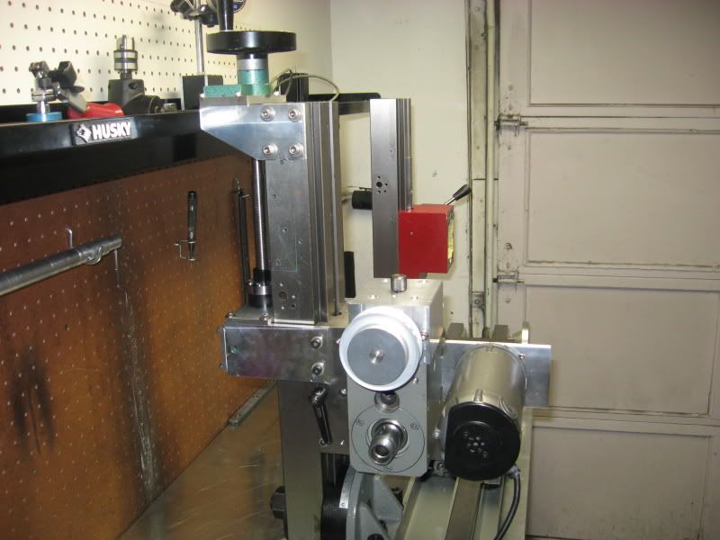
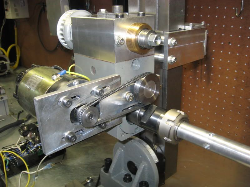
Ok, milling head installed, carriage table shortened and tapped for many mounting options, A removable straightedge with adjustable setscrews to position irregular work is also a feature of the main table.
Mill head rebuilt with new bearings, assembled to dovetail slide with 6 grade 8 fasteners and adjustable for angle. Much less overhang than a x2 mill and a much much more rigid setup!
I just popped in a linebar from a previous project to show how it will work eventually. A second rear slide will be added to support the end of the linebar. A overarm setup will be installed on the top of the mill head and will be used for horizontal arbor type cutters. I will add a y axis slide way. Perhaps a swivel compund slide.
Sorry, I don't do 3d cad. I just get a vision in my head and work from there.
Hopefully these pics will start to show how the machine will
work.
Very early satges right now and much to workout.
Steve
-
08-02-2008, 05:20 AM #5
Registered
- Join Date
- Jan 2007
- Posts
- 277
Nice work! I like it. Please continue

-
08-04-2008, 11:47 PM #6
Registered
- Join Date
- Mar 2006
- Posts
- 357
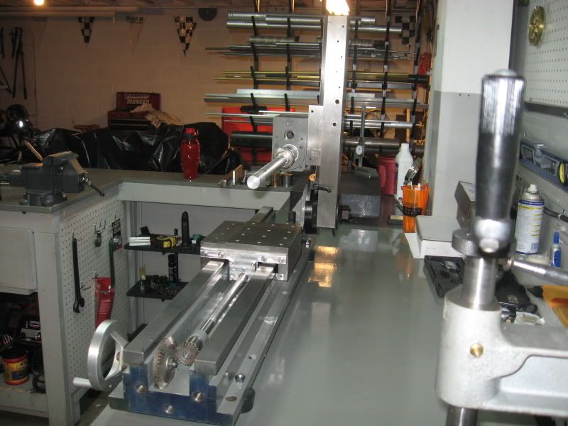
A little more progress, I am only working on it during my spare time on weekends so things will be going a bit slower now.
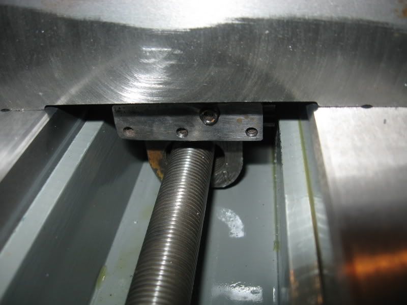
I have a lead screw drive in place for the main table now which works very nice. The hand wheel drives it at the rear via a set of bevel gears. There will be a power feed for this axis eventually.
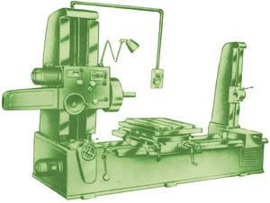
Also, just found this illustration of a small horizontal boring mill that is still being made today by Atlas Machine, an India company.
Hopefully this will help give a better idea of what I am building.
Steve
-
08-05-2008, 01:02 AM #7
Registered
- Join Date
- Jan 2007
- Posts
- 277
Thats really looking nice. I would like to build something like that in a year or so. Must finish my shop first. I want to build a boring mill big enough and heavy enough to align bore a big block V8! Or maybe I can get something like this jigmill cheap in an auction
:
-
12-02-2008, 08:49 AM #8
Registered
- Join Date
- Jan 2007
- Posts
- 277
Hows this project coming?
-
12-02-2008, 11:50 PM #9
Registered
- Join Date
- Mar 2006
- Posts
- 357
Davo,
It's coming along pretty good. I guess It's about time for an update.
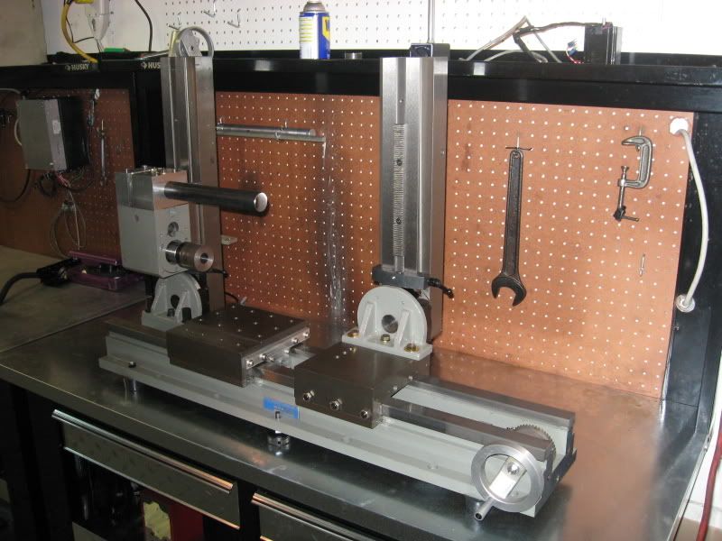
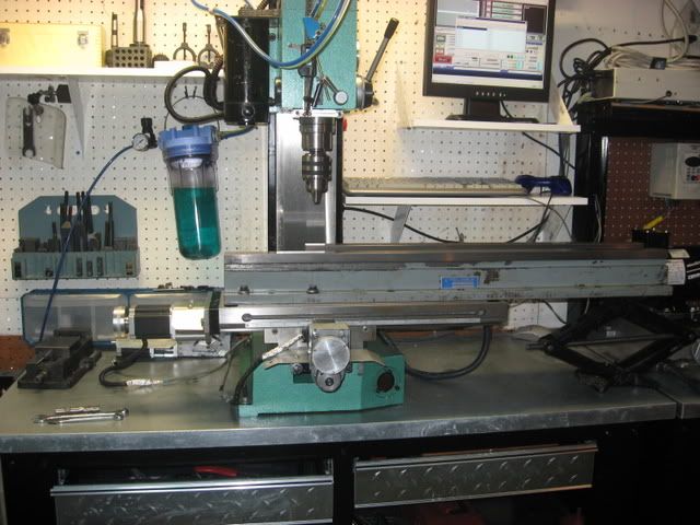
The end table and end column are installed. This assembly is fitted with a half nut for the lead screw so it can be disengaged and moved into position as needed.
The end column uses the standard rack and pinon z axis drive from a mini mill with worm feed for fine movements. I am keeping the rack and pinion on the end column as I may also mount a small drill attachment to it.
The spindle column z-axis is now fitted with a lead screw and counter balanced with a gas strut.
A 600 watt mini mill dc motor will be used for power.
I have spent a lot of time thinking of the drive system for this machine.
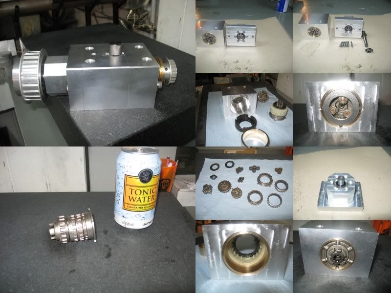
I am just about finished with a 3 speed planetary gear box for the machine which has been a bit of work.
It has ratios of 72:1, 40:1, and 13.5:1 reduction. Plenty of low speed torque!
The gearbox is also fitted with a detent clutch to limit torque to the spindle.
The planetary gears were taken from a high end Makita hammer drill. All hardened, sintered metal.
I plan on also having direct drive pulleys to the spindle for high speed operation.
Still a LONG way to go but it's getting there.
New Pics will come this weekend.
Steve
-
12-06-2008, 07:29 PM #10
Member
- Join Date
- Jul 2007
- Posts
- 59
Compliments on your neat and organized shop. I can only hope that mine will look like that someday....
-
12-08-2008, 12:10 AM #11
Registered
- Join Date
- Mar 2006
- Posts
- 357
Keith, Thanks. At times it looks as if a bomb went off but I try to keep it somewhat neat.
Well, new pics will come a little later. Just never got around to it this weekend.
Steve
-
12-14-2008, 12:51 AM #12
Registered
- Join Date
- Mar 2006
- Posts
- 357
Some progress pics-
3spd planetary gearbox-
Z-axis leadscrew-
End column-
More to come soon.
Steve
-
12-14-2008, 03:45 AM #13
Registered
- Join Date
- Jan 2007
- Posts
- 277
Very nice Steve, I need one too, cept a little bigger so I could use it to align bore V-8 engine block main bearing bores.
-
12-14-2008, 04:44 AM #14
Registered
- Join Date
- Dec 2006
- Posts
- 839
Let me see if I am understanding this right. You can mount your work on the center table there ( for instance a small transmission case), then the boring bar will go all the way through the case and attach to the tail stock kinda thing. Then the boring bar is very stable because it is attached both ends and the table will move the part back & forth to bore the part (bar is like threaded through the part).
BTW very nice work, its obvious you are taking your time and thinking this build through. I could really use something like this for working on small engine & tranny cases. I work on a lot of old school 4 speed trannies and it always helps to blue print the cases and get tolerances better.
I will be keeping up with this thread to see the end results.
Jess
-
12-14-2008, 02:04 PM #15
Registered
- Join Date
- Jul 2006
- Posts
- 1062
Nice looking project! interesting too :cheers:
Keith
-
12-14-2008, 11:07 PM #16
Registered
- Join Date
- Mar 2006
- Posts
- 357
Thanks guys.
Jess, yes that's pretty much how it will work. The end table/column that supports the end of the line bar is able to move with the center table or locked to the ways depending on the situation.
It has a half nut arrangement for the leadscrew to make this possible. To engage the half nut, there is a recessed Allen head screw on the top of the end table.
I'm thinking of biting the bullet and buying a X3 power feed unit for the X axis.
The machine will also able to be used as a lathe or light duty horizontal miller.
Steve
-
12-23-2008, 10:47 PM #17
Registered
- Join Date
- Mar 2006
- Posts
- 357
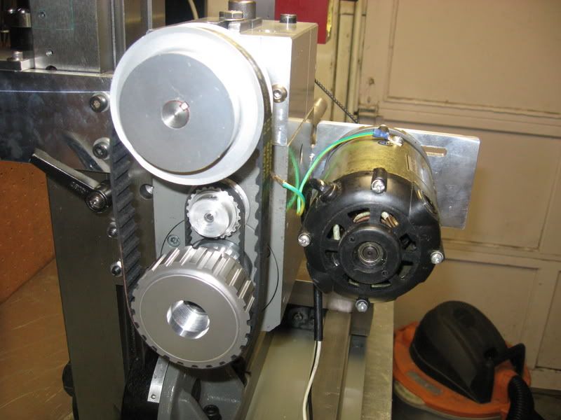
Well the mini HBM now has a working 4 speed drive system. Whooo! A lot of work and tweaking but it's done!
The triple speed planetary gearbox is practically silent. I made a few changes after initial testing. The timing pulleys on the input side just did not work out. To much noise and vibration. I switched to dual 3mm polyflex and that made a huge difference.
This spindle has more low speed torque than my x3 mill. The gearbox really multiplies the torque.
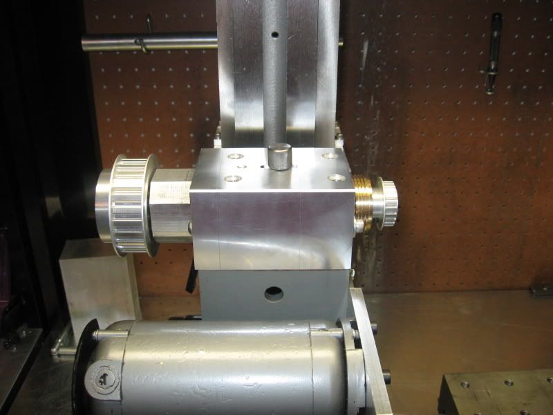
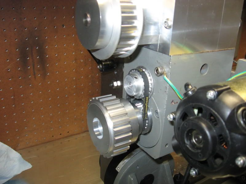
So for planetary gears 1,2,3 this is the belt setup-
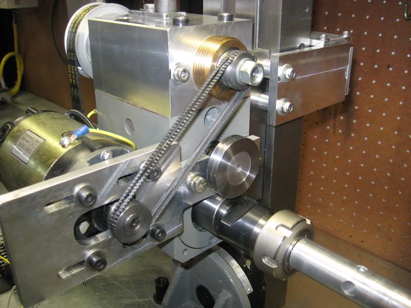
For high speed operation, the polyflex belts are moved to the lower shaft and the large timing belt removed-
And here is a 6meg video showing all 4 speeds in operation, The only noise really is from the motor. Click the link to view the clip-
http://s109.photobucket.com/albums/n...onstration.flv
Steve
-
12-24-2008, 07:21 AM #18
Gold Member
- Join Date
- Sep 2006
- Posts
- 1738
Sick! I love this thing.
-Jason
-
12-27-2008, 03:41 AM #19
Registered
- Join Date
- Mar 2005
- Posts
- 160
Movie! Show movies! I hav pop corn
Can we see this baby's test run when possible via video...pleeeease...LOL
"Are you gonna eat that?"
-
12-27-2008, 04:30 AM #20
Gold Member
- Join Date
- Jun 2004
- Posts
- 6618
This is pretty cool.
I have been considering what other type machine I could build that would be useful.
I want to see more of what it can do. I'll stay tuned.Lee


 Reply With Quote
Similar Threads
-
horizontal cnc boring machine?
By bp092 in forum Commercial CNC Wood RoutersReplies: 1Last Post: 10-25-2007, 03:51 AM -
Machinist - Horizontal / Vertical boring mill operators
By quinnj in forum Employment OpportunityReplies: 0Last Post: 10-18-2007, 05:26 PM -
Horizontal and Vertical boring mill operators
By quinnj in forum Employment OpportunityReplies: 0Last Post: 10-16-2007, 07:58 PM -
Horizontal Boring
By harryn in forum K2CNCReplies: 9Last Post: 06-30-2007, 05:37 AM -
New Photos! Horizontal Boring Mill (30HP)
By mzartop6 in forum CamSoft ProductsReplies: 1Last Post: 09-12-2006, 02:11 AM
