


While I have a couple of final tweaks to add to the one shot oiler that I will post when done (see: http://www.cnczone.com/forums/showthread.php?t=53275), I am declaring victory and moving on from basic mechanical mods to the mill.
I have been installing the IH kit (very nice kit, BTW, I like!) and just got the optical limit switches on last Saturday. There is a bit more to do there too, but it's winding down.
So, my attention is starting to turn to the electronics. I want to be able to power up this bad boy that's taking shape so nicely in my shop!
Some time ago I acquired a couple of surplus Rittal NEMA enclosures off eBay very cheaply with the thought they would serve well in this role. They are 19" x 19" by 12" deep. As part of a Labor Day sale, I acquired a Sears Craftsman "Gladiator" rolling cabinet:
Here is what one of the Rittal boxes looks like (back behind some other CNC "finds" from eBay):
These are nice heavy gauge boxes with rubber weatherproof gaskets to seal them.
The first challenge I faced was opening the box. It uses a special theft-proof key:
15 minutes worth of mill and lathe work later and I had fashioned a key from a piece of 12L14 and a 1/8" roll pin I found laying around:
<continued>
Thread: Electronics Enclosure Build
Results 1 to 20 of 75
-
10-23-2008, 02:35 AM #1
 Gold Member
- Join Date
- May 2005
- Posts
- 2502
Electronics Enclosure Build
-
10-23-2008, 02:40 AM #2
Gold Member
- Join Date
- May 2005
- Posts
- 2502
And here is what was inside yonder box:

That should work very nicely once I clear out that cage!
I drew up a preliminary layout sketch in Rhino3D:

Let me walk you through it.
First, the box will have the following inside:
- A set of 6 "Axis Modules". More on those later, but consider them to be self-contained Geckodrive sub-chassis.
- A power supply. I bought a nice 70V 1000W supply from Antek for a very reasonable price. This is the same outfit I got the toroidal transformer from for another supply I made.
- PC interface. Currently planning on a Smoothstepper.
- Miscellaneous relay and VFD controls, as well as an E-Stop circuit and other auxilliary components.
Here is a shot of the Antek supply I am using:

<continued>
-
10-23-2008, 02:46 AM #3
Gold Member
- Join Date
- May 2005
- Posts
- 2502
OK, now what's up with these Axis Modules?
Here is a 3D model of one:

The module is laying face down in that view. The blue box on top is a Geckodrive--servo or stepper. I'll be using servos for 4 of the 6 channels.
The red box is a heat sink to keep the Gecko happy.
The components directly under the Gecko are (front to rear) a DB-9 connector for the servo encoder, a 3AG fuse holder, and an IES power connector. For my servos I plan to use regular PC power cords to connect them up.
Lastly, the purple object at top is a load meter.
This is basically an ammeter that shows how much current the axis is drawing. I won't include the load meter on every axis, but it is useful for the main X, Y, and Z axis when adjusting the gibs. I came across a procedure for a commercial VMC that recommends adjusting the gibs until the load is about 1/3 of the allowable on the axis servo drive. I think it'll be interesting to be able to monitor these loads over time as well. The meters are cheap from MPJA and I just read the supply current from the DC supply before it gets to the Gecko.
Reading the load in this way has been somewhat controversial on these boards. I'll build one axis module and check it out before bothering with the other 2.
-
10-23-2008, 03:07 AM #4
Registered
- Join Date
- Aug 2007
- Posts
- 558
Bob, that's looking good! Is the screen a touchscreen?
I like the look of the Antec power supply, it's quite tidy and looks well made. I might give them a try next time.
You'll like the Smoothstepper, They're great
Best regards,
Jason
-
10-23-2008, 05:42 AM #5
Registered
- Join Date
- Jun 2005
- Posts
- 1015
Looking good bob. i integrated my pc into the control box that way its all in one water proof package. i'm still looking for a good way to bundle all my wires up, but i don't know if i've finalized all the locations yet.
-
10-23-2008, 07:21 AM #6
Registered
- Join Date
- Jan 2007
- Posts
- 210
If you put your pc in the same sealed box with your drives and power supply it's going to get pretty toasty in there and your cpu might not be too happy. Originally Posted by Runner4404spd

Larger enclosures are better as it's the surface area of the cabinet that determines how much heat is dissipated to the external environment.
You can get an indoor/outdoor thermometer and place the outside sensor in the box and close the door to see how much temp rise you get. If it stays below 110/120 F you should be ok. At about 140/150 most computers will start to get flaky.
BobYou can always spot the pioneers -- They're the ones with the arrows in their backs.
-
10-23-2008, 07:37 AM #7
Gold Member
- Join Date
- Dec 2004
- Posts
- 1865
Unlike me who gets flaky at 102f. Originally Posted by CarbideBob
:cheers: When that happens apply lots of alchohol:cheers:
When it comes to enclosures, the bigger the better, especially if there is a cooling concern. Or if you have big hands.Warning: DIY CNC may cause extreme hair loss due to you pulling your hair out.
-
10-23-2008, 10:31 AM #8
Gold Member
- Join Date
- May 2006
- Posts
- 2420
Nice work on the key Bob, shame you live so far away I could have sent you a couple, I have a small pile of plastic ones lying around somewhere (they come with a new cabinet), no matter as they won't have the same "character" as your version
Looking forward to seeing the finished enclosure !
Cheers.
Russell.
-
10-31-2008, 06:07 AM #9
Gold Member
- Join Date
- May 2005
- Posts
- 2502
Thanks for all the kind comments, and yes, I plan on a touchscreen. In fact, I'll likely build a fancy control panel and integrate the touchscreen at some point, but not until after everything is working and I can use the CNC to make that fancy control panel!
Thought I'd share a bit more recent progress.
Here is a typical Martian War Machine, oops, I mean Gecko Module:

Pretty straightforward job on the mill. The legs are stainless, 304 unfortunately (it's not nice to work with). However, all I had to do was cut the legs to length, and then drill and tap either end for some 8-32's. Fortunately I had some brand new spiral flute taps I had gotten from Enco, and they made even that nasty 304 not such a bugger.
About the only remarkable thing I did to make these guys was to do a template from a 1:1 scale printout from my CAD program and then go on to make a drill jig from a piece of steel plate:

It made drilling all the holes in the heat sinks super easy and fast, and made sure they were all in exactly the right place.
I got my IH optical limit switches installed too:

They're really neat. Oddly, the cast iron was particularly tough on the column. I wound up having to sharpen my drill bits in the Drill Doctor, so maybe it was just that I started with a dull bit. Most of the cast iron is really nice to work on.
Next, I got a nice collection of IES power connectors, 3AG fuse holders, and female DB-9 connectors as well as some 15A ammeters. I ordered it all from MPJA, which is really cheap if they have what you want.
So, time to start thinking about the front panels on the axis modules. First thing was to make another 1:1 template on the CAD program:

I hate making up these panels because its just drudgery. Go buy a hole saw for the big panel cutout. Drill corner holes and mill or nibble for the square openings. When I get the CNC, that sort of thing will be a thing of the past.
<continued>
-
10-31-2008, 06:10 AM #10
Gold Member
- Join Date
- May 2005
- Posts
- 2502
Meanwhile, I could just tee these panels up on the mill and deal with it, or I can look around for a more fun way to do it.
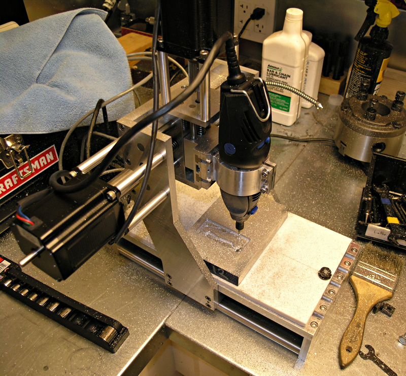
I've toyed with 2 options. First one is to fire up Ye Olde Widgitmaster mini-router for the panels. Should be a fine job for it:
The other alternative I'm considering is putting together a little punch and die action for my 50-ton H-frame. Sure would be nice to have a punch capability on that thing. It'd be a fair amount of work to create a punching attachment, but I'll bet I'd get a lot of use from it.
Will have to think about which of the three options to pursue.
Cheers,
BW
-
11-03-2008, 06:25 AM #11
Gold Member
- Join Date
- Feb 2006
- Posts
- 7063
Bob,
We're practically neighbors - I'm up in Bonny Doon. I've got a CNC'd knee mill. If you need to do those panels, or anything else, let me know. My machine would knock those out in no time. You can contact me at: [email protected]
Regards,
Ray L.
-
11-03-2008, 03:58 PM #12
Gold Member
- Join Date
- May 2005
- Posts
- 2502
Ray, thank you for the kind offer. I got busy over the weekend and have them nearly finished.
Best,
BW
-
11-03-2008, 07:58 PM #13
Gold Member
- Join Date
- Feb 2006
- Posts
- 7063
Bob, Originally Posted by BobWarfield
Cool! If the need arises, feel free to contact me. I've been watching your site for years. You've done a lot of nice work. One of these days I plan to build a big disc sander similar to the one you built.
In fact, I tried to contact you last fall, when I was shopping for a mill - wanted to come down and see your IH, as it was a top-contender at the time. I ended up buying a new BP clone instead, which I could not be happier with. Just completed the last major bits of the CNC conversion a few weeks ago, and it's working just about perfectly. I can now crank out chips at a hellacious rate! What to do with them all..... Gonna have to take up casting....
Regards,
Ray L.
-
11-16-2008, 08:49 PM #14
Gold Member
- Join Date
- May 2005
- Posts
- 2502
A bit more progress to report after having most of yesterday afternoon available in the shop.
First, I soldered the cables on my servo motors. They come with short tails, so I just soldered on some IES power cords to extend their reach to 10 feet. These are the same power cords you'd use on a computer with the distinctive three pronged connector. For splicing, I like to protect each conductor with a piece of heat shrink tubing and then protect the overall splice with another piece. Unfortunately, I didn't have the latter 1/2" tubing on hand, so I did 2 of the cables with electrical tape wrap. When I ran out of even the smaller diameter I had to make a run to Radio Shack for it. Here are the three servo motors that replace my 3 handwheels on the mill:

You can see an additional white connector on each motor that looks like a serial port connector for a computer. That's the encoder connector. Encoders are one of the big things that separate servos from steppers. You can drive a CNC with either, but servos offer higher performance (at a higher cost, natch!) than steppers. I like using standard connectors so I can buy off the shelf cables already made up. Hence the IES power cords, and now these serial port connectors. The latter were installed by Homeshopcnc, which is where I got my servo motors. To give you an idea, these are 850 oz/in torque motors that cost $235 apiece with the encoder housings, so they're not cheap for this kind of performance. Steppers in that range would cost circa $130.
Next, I managed to finish a couple front panels for my axis modules. Here is one mocked up with the parts, but not wired:

So the encoder plugs in to the left of the fuse, and the servo power cord to the right. I can get at the fuse without opening up my enclosure with the panel mounted holder. The ammeter is a peculiarity of my setup. I wanted to measure the current draw of each axis as a way of understanding how "tight" the axis is in order to adjust the gibs and monitor wear. Remember, you lose feel for gibs with a CNC!
Here is the back of the panel:

As you can see from the photos I have an issue with meter clearance and the mounting bolts, so I made an oversized hole to try to create some "wiggle room". This happened due to an error in laying out the big square face during the CAD design. What I need to do is relocate the whole meter 1/4" down the panel and all would be well.
I've gotten it close enough, I think. I can't go much further or I'll lose the mounting holes for the meter as you can see in this behind shot. In the end, I'm planning to remake these panels anyway once the CNC is up and running. I'll make them out of 1/4" aluminum plate and put some engraving and other decorative touches on so they'll look a lot nicer.
Still an awful lot to do on this project!
-
11-18-2008, 03:47 AM #15
Registered
- Join Date
- Dec 2006
- Posts
- 839
Hello BOb,
I really like the meters to monitor the servo's & drives. The IES cabling is nice and clean also. One thing about the IES style cabling I thought about as a possible problems is having a dissconnect while powered up.
If I understand right, if this happens its possible to fry a drive? There pretty possitive in there connection and it would take a bit to pull them out though. If this is true that it could fry a drive maybe some kinda locking tab/clamp could prevent it. Just something to think about, I am
not %100 sure that a dissconnect would burn a drive, but it seems I read that somewhere.
Jess
-
11-18-2008, 04:32 AM #16
Gold Member
- Join Date
- May 2005
- Posts
- 2502
Jess, you are correct, an unplug would be bad for the drive.
I've got a lot of slack available though, and the plug is at the stationary end of things. Those plugs are pretty sticky in my experience, so I don't expect to have a problem. Lots of locking connector styles available for someone that wants to avoid the risk though.
Cheers,
BW
-
11-18-2008, 07:20 PM #17
Registered
- Join Date
- Aug 2008
- Posts
- 573
Hi Bob,
I'm surprised you chose IEC mains connectors, The 'cold' type you've used are only rated to 6A (@230vac) Obviously, they will take current more at lower voltage, but watch out for any heating at the molded sockets, as the contact pressure is notoriously poor (especially after a few insertions).
Also, make sure you label the outputs clearly; you don't some helpful person plugging it into the mains.
Personally, I'd have chosen either a cannon/xlr, like the 3pin 16A Neutrik attached, or Neutrik 'speakons', which are designed for loud speakers, but are rated to 50A per contact and are 4 pole. Ready made leads are available; a cheap 3m (10') two core (2.5mm^2) would be about £10+tax over here.
-
11-18-2008, 09:53 PM #18
Registered
- Join Date
- Dec 2006
- Posts
- 839
Good deal Bob,
atleast I know for sure the results of such a thing happening.
These projects require a hugh amount of work and funds, I am sure if you see a need for a redesign or replacment you will take care of it. Like your module pods mounting plates, that will be nice after you get up and running, then go back and remake the face/mounting plates. Sometimes its best not to put to much into something until you have hands on feedback, or can step back and see the big picture so you know what you want & need.
Really looking forward to seeing your machine in action. Ofcourse I am sure you are doing the same, it can be a long road.
Jess
-
01-04-2009, 05:31 AM #19
Gold Member
- Join Date
- May 2005
- Posts
- 2502
OK fans, its finally time to lay out a lot more progress. It's been a little while since I reported. I reckon I have invested 2 part time weeks (nights and weekends), plus quite a bit more time during the week between Christmas and New Year's. So, I've got some show and tell.
First, I took my air shear to the enclosure to cut openings for the axis modules, front panel, and rear panel:

Then, I got the various major electronic components mounted on a plate that goes into the enclosure:

I spent a lot of time researching how each of those boards works and getting together a complete wiring diagram before I tried wiring anything up. Lots of hours racked up on the Internet!
Then, I spent the few days right after Christmas wiring it up. Right now, I consider it a breadboard prototype, but I can successfully spin 1 servo under Mach 3 control:

It took me the last 3 days to debug the thing well enough to be able to do that!
-
01-04-2009, 05:39 AM #20
Gold Member
- Join Date
- May 2005
- Posts
- 2502
I know how frustrating that debugging part can be, both since I've done it for other projects, and because of all the time I spent reading about other people's debugging woes trying to get ideas to try to fix my own problems.
Because of all that, I created a page that documents exactly the process I went through to get the axis working:
http://www.cnccookbook.com/CCMillCNCDebugging.htm
That page is by no means a general recipe, but it might help someone understand how I went about it.
In addition, here is the list of things I had to change from my original wiring to get the servo going:
1. Set CNC4PC Master Control Board DIP switches for G320. It acts funny on the other board types whether or not Err/Res is connected.
2. Discovered I had mislabeled the leads from my front panel for the "Start" and "E-stop", so they were connected backwards.
3. Reverse the motor connections because they were backwards compared to what the encoder indicated, causing an immediate servo fault.
4. In doing #3, I reversed the wrong leads and had to replace the power supply rectifier. I don't think I blew the Gecko, amazingly! You can see the replacement rectifier set up I'm using temporarily for test while I wait for a new board from Antek (generously offered for free!).
5. Connect a 47K ohm resistor across pins 1 and 3 of the G320 to ensure the bridge initializes properly. This was buried in a hard to find Mariss note on CNCZone, but will be a change in future Gecko servo drives. If you have flakiness with startup faults, Mariss recommends it. Sure helped me!
6. Now I was getting the servo to hold position, so I played with the tuning trimpots a bit. It makes little ticking noises, but doesn't really quite "hum".
7. In Mach3, set Step/Dir to ActiveLo. Set pulse width to 5 (the pulse width may be ignored for Smoothstepper, but I was taking no chances!).
8. Connect "Common" on G320 to +5V on breakout card instead of Ground. Another one that's easy to miss unless you read a lot of posts on various boards! I used ground because "Common" meant ground to me. But that's not how it works! I didn't figure this out until I noticed the G320 manual labels "Common" +5V instead of calling it common. Sure wished they'd left it labeled that way!
9. Set up the proper motor tuning parameters on Mach3. IH says 115 IPM speed and 0.15g of acceleration, according to another post I found. I also needed 28,240 steps to move 1".
10. Set the Smoothstepper jumpers to actually provide +5V to the breakout board. Otherwise, the terminals marked "+5V" are 0V! That meant that my "common" change was doing nothing. I didn't think of this until I went searching the Smoothstepper manual for something I'd missed and spied the pix of the jumpers. Made me wonder, so I tried it. Voila! Suddenly things worked.
Now I can spin the servo this way and that with Mach3. It can still fault if I rapidly change directions at full jog, but that's just tuning and I need to set it properly on the actual machine instead of with servos flopping around on the floor.
I must admit that per the discussion on the Cookbook Blog on the Eternal Servo vs Stepper Jihad, it was a lot harder to spin a servo than a stepper. In general, I encountered a lot of less than obvious things including the CNC4PC DIP switch settings, need for the 47K ohm resistor, and bizarre experiences with "Common", which has to be +5V, and which didn't get +5V until the Smoothstepper jumpers were enabled.
I hope these notes help the next guy who searches CNCZone for "servo fault g320 problems" as I did! FWIW, I think I read every post on G320's on this board, on the Mach3 board (both Yahoo and Artsoft's) and on the Geckodrive boards.
The Internet is your friend!
Cheers,
BW


 Reply With Quote
Similar Threads
-
Add a Hinge to your Electronics Enclosure on your Syil X3 CNC Mill
By Chrisjh in forum Syil ProductsReplies: 5Last Post: 04-20-2008, 01:16 PM -
Electronics Enclosure Sources?
By Chris64 in forum CNC Machine Related ElectronicsReplies: 2Last Post: 12-20-2007, 07:12 AM -
Electrical/Electronics Enclosure
By audioandy1762 in forum DIY CNC Router Table MachinesReplies: 0Last Post: 02-27-2007, 01:32 PM -
Not sure what to do about electronics enclosure
By phantomcow2 in forum Benchtop MachinesReplies: 18Last Post: 02-08-2007, 05:29 PM -
Electronics Enclosure Box
By JavaDog in forum CNC Machine Related ElectronicsReplies: 9Last Post: 04-22-2005, 02:00 AM
