


I want to purchase a Enclosure for my Taig Mill, I know I can make one but barely have time to make parts, Plus I want it Nice if you know what I mean
I seen IM services makes one but its not wide enough for the Table to go side to side..
Results 1 to 20 of 24
-
12-14-2008, 09:15 PM #1
 Registered
- Join Date
- Nov 2007
- Posts
- 23
Anyone sell an Enclosure for the Mill
-
12-14-2008, 10:12 PM #2
Registered
- Join Date
- Nov 2006
- Posts
- 1036
There's a guy with an interesting blog at http://www.nyccnc.com who has a real nice enclosure that I believe he purchased from http://www.lococnc.com
link to his enclosure:
http://www.nyccnc.com/Herbie/HERBIES..._is_done!.html
Good luck
Don
-
12-14-2008, 10:17 PM #3
Registered
- Join Date
- Nov 2007
- Posts
- 980
I'm doing this as well but I'm still in pencil sketch mode at this point.
Will you be doing a coolant setup?
DaveDave->..
-
12-15-2008, 01:33 AM #4
Registered
- Join Date
- Nov 2007
- Posts
- 23
Yes using a pond pump... Originally Posted by fretsman

-
12-15-2008, 03:05 AM #5
Registered
- Join Date
- Nov 2007
- Posts
- 23
I went to the lococnc site but did not see any,,sent them an email Originally Posted by DonFrambach
-
12-15-2008, 06:03 PM #6
Registered
- Join Date
- Mar 2003
- Posts
- 270
What size do you need to fit a Taig? Originally Posted by cnccustom
Fred Smith - IMService
http://www.imsrv.com
-
12-15-2008, 06:08 PM #7
Registered
- Join Date
- Nov 2007
- Posts
- 980
The one I was after was 30" High X 26" deep, X 42" width.
DaveDave->..
-
12-15-2008, 07:36 PM #8
Registered
- Join Date
- Nov 2007
- Posts
- 23
We need 42 inches wide for the Taig Originally Posted by imserv
as fretsman says 30" High X 26" deep, X 42" width would be perfect
-
12-15-2008, 09:37 PM #9
Registered
- Join Date
- Mar 2003
- Posts
- 270
 We could do it in the 5 sided, plexi, with aluminum T-slot frame. Originally Posted by fretsman
Similar to this:36W x 24D x 24H enclosure
Your size is probably too big for a top hinged door. A vertical slider would probably be better. Would that work?
Flood coolant might be a problem, but if you put the enlcosure on a non-porous tabletop, you could seal around the inside frame with RTV, and install a drain hole. With a mister, you might need to install some windshield wipers
Fred Smith - IMService
-
12-15-2008, 09:42 PM #10
Registered
- Join Date
- Nov 2007
- Posts
- 23
after some searching I will make my own with 80/20 material and 1/4 inch coroplast for the sides and back ,plexi glass front doors, Thinking of leaving the top open , not sure yet
Thanks
-
12-15-2008, 10:02 PM #11
Registered
- Join Date
- Nov 2007
- Posts
- 980
Originally Posted by imserv
Thanks, Fred, I'll give you a shout when I get closer to doing this if I don't end up doing it on my own-
DaveDave->..
-
01-08-2009, 03:53 PM #12
Registered


- Join Date
- Sep 2007
- Posts
- 48
If your going to run flood coolant don't leave the top open. On my first enclosure I was running flood coolant at up to 4gpm. Originally Posted by cnccustom
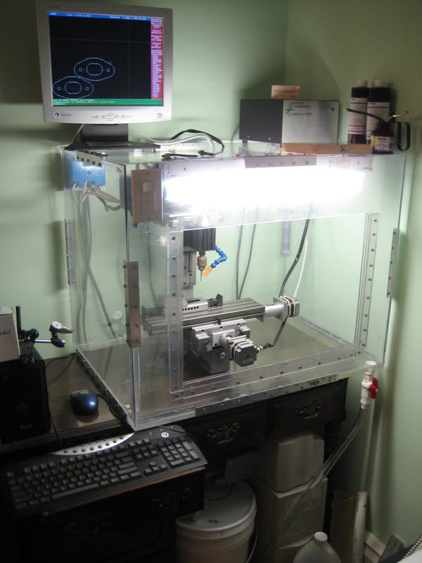
Depending on the part geometry, tool speed, and flow rate, the coolant would easily spray up to the height of motor, sometimes higher. When I disassembled the enclosure the top panel was covered in dried up coolant (I run water based KoolMist 77). Granted I've had some rather unusual setups on my mill but in your case I'd still suggest taking the "better safe than sorry" approach
-
01-09-2009, 03:48 PM #13
Registered
- Join Date
- Feb 2007
- Posts
- 456
OK, I have to ask, 4 GPM and 8 (yes eight) nozzles? Perhaps a bit of overkill?
What are you cutting?
Unless you are cooling your coolant I would think that your putting as much or more heat into it through the pump as what your making with the tool. As a point of comparison, I built a small testbed for a research group here at the university. It constantly recirculates 20 gallons of water at about 10 GPM through 1" pipe. After 2-3 hours the water temp is near 150 deg F.Jeff Birt
-
01-09-2009, 07:01 PM #14
Registered
- Join Date
- Sep 2007
- Posts
- 48
 It's a fair question, maybe this will clear it up for you... Originally Posted by Jeff-Birt
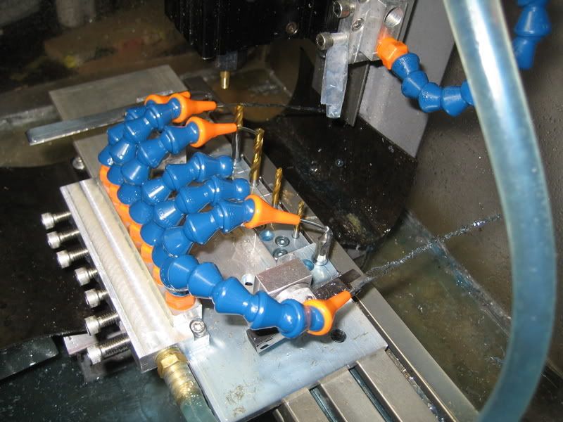
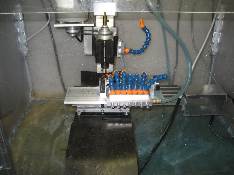
My mill is setup to be used as both a CNC mill, and a gang tool lathe. It only takes about 2 minutes to switch between setups. 7 of the nozzles are mounted on the gang tool lathe setup's coolant manifold. This allows me to adjust the coolant pressure/flowrate and angle for each turning tool involved in the process. When this picture was taken I was still waiting for another pack of nozzles to arrive hence there's a few missing. When the taig is being used as a CNC mill it has 2 nozzles attached (only 1 is attached in the pictures) to a coolant manifold on the spindle. Coolant is useless unless it is getting to the cutting interface between the end mill and the part. With the pressure/flow rate my system provides, I'm able to adjust the location and pressure/flow rate of the coolant nozzles to suit the particular part being made.
For example; With only 1 coolant nozzle, flooding the tool from it's right hand side, when cutting from left to right into the side of a block, the coolant will be blocked from the actual cutting area of the endmill by the top surface of the block. While this does cool the work piece, the cooling system is failing in it's primary purpose to lubricate the interface between the shearing material and the cutting tool.
So in short more nozzles provide more options for proper cooling, lubrication, and chip removal.
Also the pump in use is a non-contact vane design (essentially a pond pump), my best guess is that the pump you used for that experiment was a centrifugal pump coupled to a decent sized motor? Also the pump itself is fully submerged in 5 gallons of coolant, increasing the surface area related to heat transfer significantly. Thus far just based on observation, the coolant remains just above room temperature when in operation, even after long 6-8 hour programs in 6061.
You gave me a good idea for new enclosure i'm working on now though. Adding a force convection cooling system on the high pressure side of the pump would help drop the temp. Thanks, it was something that had not crossed my mind.
-
01-09-2009, 08:59 PM #15
Registered
- Join Date
- Feb 2007
- Posts
- 456
Ah! That explains a lot. My own preference might be two use one or two longer nozzles pointed up at the workpiece (but hitting tip of tool), I'm glad you found a solution that works for you though. More than one way to skin a cat and all that.
Yes it is a centrifugal pump, as that is the pump design they needed to test, as I recall it is only a 0.5~1hp motor. I would be interested the measures temperature of your current set up, compared to when you add a cooler. One easy solution would be to find a used Miller tig-torch cooler. They are about the size of a small six-pack sized igloo cooler. They have a built in pump, fan and radiator.my best guess is that the pump you used for that experiment was a centrifugal pump coupled to a decent sized motor? ..snip...Thus far just based on observation, the coolant remains just above room temperature when in operation, even after long 6-8 hour programs in 6061.Jeff Birt
-
01-11-2009, 12:11 AM #16
Registered
- Join Date
- Sep 2007
- Posts
- 48
Well I'll be using the pump I already have, it's worked outstanding thus far and is robust enough to handle small particulate in the coolant. I was thinking about using something like this: Originally Posted by Jeff-Birt
http://www.newegg.com/Product/Produc...82E16835108098
coupled with 3 x 120mm fans, it should be sufficient to maintain the flow rates and further cool the fluid. The only thing I haven't figured out yet is how I'm going to filter the coolant to remove all of the swarf and particulate so that it does not enter the radiator.
-
01-11-2009, 04:12 PM #17
Registered
- Join Date
- Nov 2007
- Posts
- 980
Didn't you used to have a video on youtube for the gang set up on the Taig mill? I bet that would've helped iilustrate what you were trying to convey with your coolant setup.
Always loved that one
DaveDave->..
-
01-11-2009, 05:40 PM #18
Registered
- Join Date
- Sep 2007
- Posts
- 48
Yup I sure do: Originally Posted by fretsman
[ame="http://www.youtube.com/watch?v=0d2AcT_rJig"]http://www.youtube.com/watch?v=0d2AcT_rJig[/ame]
This was one of the bigger reasons why I'm upgrading my taig now with larger steppers, a new controller, ball screws, etc... The slow rapid and feed speeds have finally gotten to me and I want more
-
01-11-2009, 07:00 PM #19
Registered
- Join Date
- Nov 2007
- Posts
- 17
I'd love to hear about your experiences upgrading the Taig with ball screws when you get around to it. I'm happy with the setup the way it is now, but I can see wanting more eventually Originally Posted by Anokiernan
Chris
-
01-11-2009, 10:48 PM #20
Registered
- Join Date
- Sep 2007
- Posts
- 48
I'll certainly do so, I'm actually taking the taig apart right now to measure some of the features. It's looking quite doable to me, has anyone done this before? I haven't been able to find any others who have converted the taig to ball screws. Granted it will be only a marginal increase in performance over the 1/2-20 leadscrews with preloaded nuts, it will increase rapid speeds outrageously while maintaining or even improving the thrust capabilities and repeatability using 425 oz/in steppers. Originally Posted by cmanning

 Reply With Quote
Similar Threads
-
80/20 TAIG CNC Mill Enclosure
By tikka308 in forum Taig Mills / LathesReplies: 17Last Post: 12-06-2007, 11:43 AM -
Looking for a mill enclosure
By adryan in forum Vertical Mill, Lathe Project LogReplies: 0Last Post: 11-20-2007, 08:07 AM -
DIY Mill Enclosure
By ixen.yeo in forum Benchtop MachinesReplies: 3Last Post: 11-01-2007, 04:59 AM -
Want to make an Enclosure around my Taig Mill!
By CROSSHATCH in forum Taig Mills / LathesReplies: 53Last Post: 10-30-2007, 04:09 PM -
8020 CNC mill enclosure
By VTX in forum 80/20 TSLOTS / Other Aluminum Framing SystemsReplies: 1Last Post: 01-24-2007, 01:18 AM
