


Originally Posted by dynosor

It looks that way but there is still alot to do.
5.5:1 if built to print
There are no crowns, pistons are flat top. There will be no relief cuts. Plenty of room for valves to open. Lift is only .070 inches. If someone were to raise the compression by making a domed piston then relief cuts might be needed.
Thread: Model V8 engine plans required
Results 241 to 260 of 525
-
05-30-2011, 08:50 PM #241
 Registered
- Join Date
- Dec 2006
- Posts
- 603
-
05-31-2011, 12:28 AM #242
Registered
- Join Date
- Oct 2006
- Posts
- 708
Thanks Steve Originally Posted by stevehuckss396
A compression ratio of 5.5:1 seems low. Is this for the engine with the blower or simply to reduce stress on the engine?
What fuel will you be using?
-
05-31-2011, 12:48 AM #243
Registered
- Join Date
- Dec 2006
- Posts
- 603
That's about right for a table top runner if you want a good idle. My 1928 ford had a CR of 4.25:1 so it is plenty to get it running. Why go higher if you don't need to. The blown motor will be the same. If it prooves to low, I'll make a new set. Originally Posted by dynosor
-
06-02-2011, 07:19 PM #244
Registered
- Join Date
- Oct 2005
- Posts
- 31
Has anyone ever seen a miniature dynomometer for engines like these? It'd be really neat to be able to hook something like this up to a dyno and see what kind of crank horsepower she's really putting out. It'd be nice for tuning too.
-
06-03-2011, 04:54 AM #245
Registered
- Join Date
- Oct 2006
- Posts
- 708
Originally Posted by harley573
The simplest "dyno" is a propeller. For a given diameter and pitch, the maximum speed the engine can drive the prop is a good indicator. You need an approriate prop for a given expected rev range and ensure it is balanced.
It would help to use a common RC plane prop of known standard. Then go and talk to the RC crowd and ask what power it takes to spin a given prop at a given speed.
If you chase peak output, your model engine is more likely to frag itself, so don't be too greedy.
-
06-07-2011, 12:21 AM #246
Registered
- Join Date
- Dec 2006
- Posts
- 603
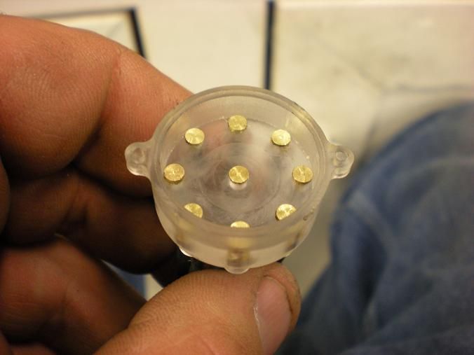
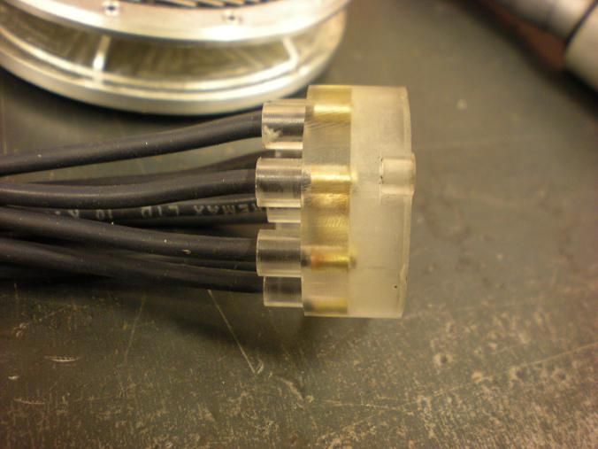
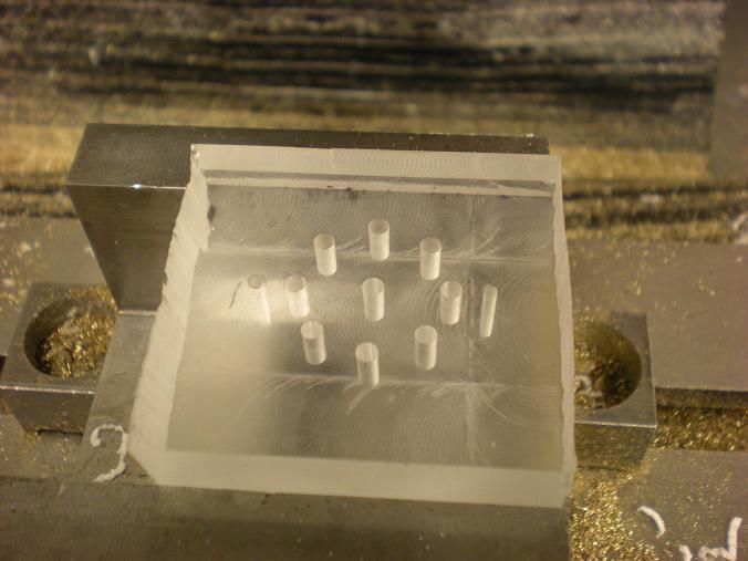
The electrodes were made .002 larger than the hole in the cap. The wire gets threaded thru from the bottom and the brass is pressed into the cap.
-
06-07-2011, 01:40 AM #247
Registered
- Join Date
- Oct 2005
- Posts
- 31
That is so freakin cool!
-
06-08-2011, 11:30 AM #248
Registered
- Join Date
- Jan 2007
- Posts
- 76
Web page for "simple dyno"
SimpleDyno
-
06-14-2011, 12:23 AM #249
Registered
- Join Date
- Dec 2006
- Posts
- 603
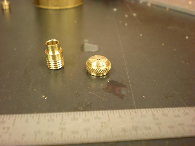
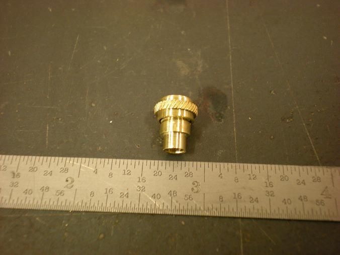
Made a few pieces for the fuel tank. I have been in a lazy mood for some reason and wanted to do something to keep the train rolling.
Bottom Fitting
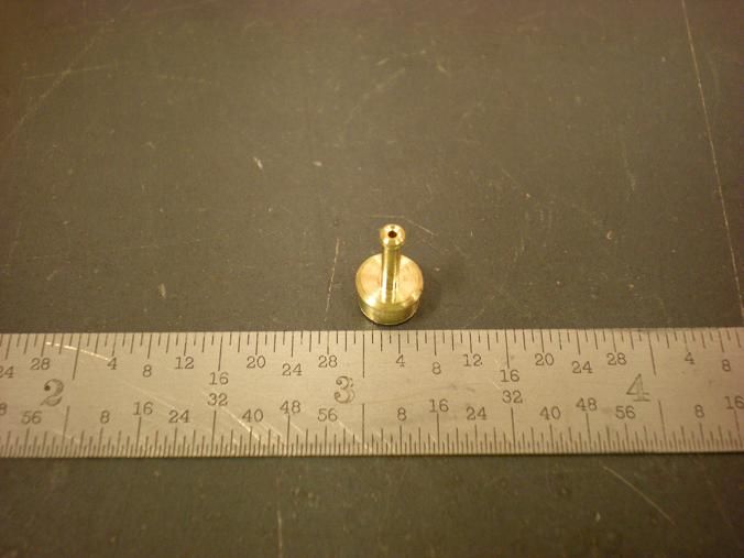
Filler neck
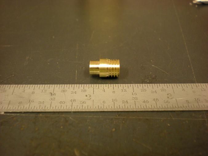
Gas cap. I was going to knurl the part but the tool was set to high. Gave it a go and decided I like the way it looks so it will stay this way.
-
06-14-2011, 09:18 PM #250
Registered
- Join Date
- Oct 2005
- Posts
- 31
Speaking of "keeping the train going", any idea on a timeframe for plans release? I am super pumped to get started on a mini-V8 of my own!
-
06-14-2011, 09:32 PM #251
Registered
- Join Date
- Dec 2006
- Posts
- 603
Originally Posted by harley573
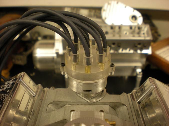
Soon as i'm sure this thing works. Just last week I made some changes to the distributor. It's much better than what I originaly designed. couple more months
-
06-14-2011, 09:35 PM #252
Registered
- Join Date
- Oct 2005
- Posts
- 31
That sounds awesome. I can't wait!
-
06-15-2011, 12:58 AM #253
Registered
- Join Date
- Dec 2006
- Posts
- 603
Originally Posted by harley573
I know waiting sucks but I don't want to release something that's crap. The drawings keep getting better because there is myself making parts and changing things for the better and there is someone else drawing the engine in solid works from the current drawings and finding some missing dimensions and making sugestions to make the drawings easier to follow.
Soon!!
-
06-15-2011, 02:14 AM #254
Registered
- Join Date
- Jan 2007
- Posts
- 76
Steve,
Nice work.
Working on a v8 here and wondered what material you used for distributor.
I have seen reference to corian in other places but not sure if it available here in Aus. I had been thinking about casting in Bakolite but base materials for this is difficult to source also.
Once again, nice work.
Jeff
-
06-15-2011, 02:38 AM #255
Registered
- Join Date
- Dec 2006
- Posts
- 603
Originally Posted by bluejets
Did you mean the cap? If so I used a surplus piece of 1-1/4 thick "bullet proof glass" Also known in the states as "lotto glass" because it was always installed in the stores that sold lottery tickets. Not sure what it is but it is some kind of polycarbonate plastic. Machines like a dream.
-
06-15-2011, 12:31 PM #256
Registered
- Join Date
- Jan 2007
- Posts
- 76
Thanks Steve.
I think it might be called Lexan here . A bit like Perspex but as tough as nails. I think it is only available here up to about 1/2 inch thick.
If yours stands up to the heat ok, maybe a fibreglass dizzy cap would be ok also.
-
06-19-2011, 07:13 PM #257
Registered
- Join Date
- Dec 2006
- Posts
- 603
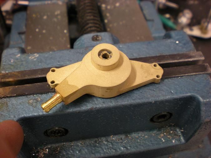
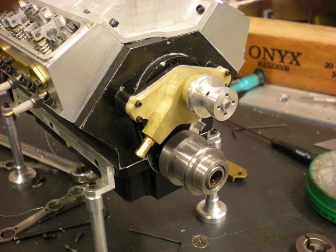
Scratch water pump off the list. Instead of tapping a hole to thread a fitting in the pump, I decided to recycle the fitting in the water neck and just solder it in. I had to sand blast the paint off and the rest was easy.
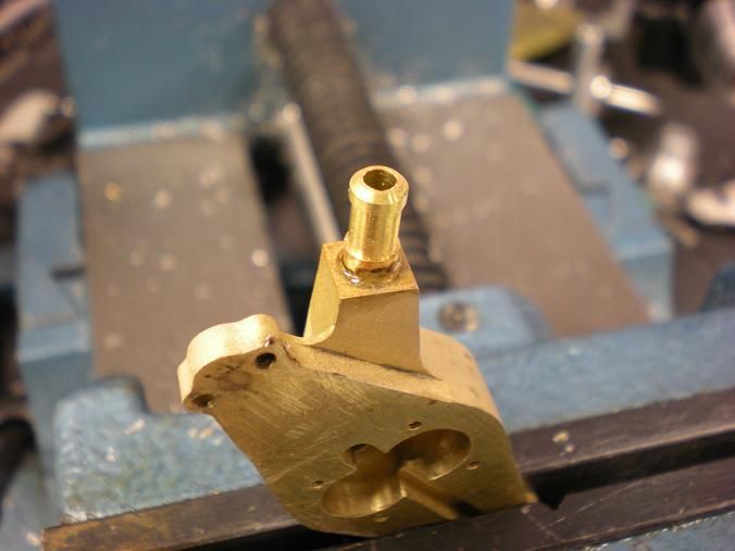
Still going to need some paint but the pump is 100%
-
06-19-2011, 08:55 PM #258
Registered
- Join Date
- Oct 2006
- Posts
- 708
Originally Posted by stevehuckss396
Jolly good. Do you have pictures showing cooling channels in the heads/block? Thanks
-
06-19-2011, 09:32 PM #259
Registered
- Join Date
- Dec 2006
- Posts
- 603
Originally Posted by dynosor
No I don't. The water jackets were cut into the block before the liners were pressed in.
-
06-25-2011, 08:59 AM #260
Registered
- Join Date
- May 2005
- Posts
- 394
Stumbled across this thread by accident. I read through the entire thing. great work. chalk me up for a set of plans along with everyone else.

 Reply With Quote
Similar Threads
-
Engine Plans
By nzer in forum MetalWork DiscussionReplies: 1Last Post: 08-03-2012, 05:14 PM -
I.C. engine plans
By cumminsman in forum I.C. EnginesReplies: 7Last Post: 04-10-2012, 11:43 PM -
Does anyone have any good jet engine plans?
By flyguy1254 in forum Hobby DiscussionReplies: 18Last Post: 04-16-2010, 10:28 AM -
Jet Engine plans
By godspeed in forum Hobby DiscussionReplies: 3Last Post: 05-18-2007, 11:34 AM
