


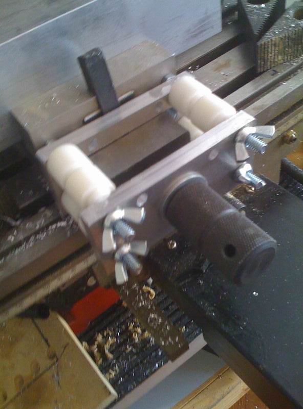
They say that necessity is the mother of all inventions, well I wanted to machine a large chunk of alu in my mill and the small vises I have aren't big enough, so I designed a way to extend its travel a little without machining the vise itself.
The white thingies are delrin bushings I had laying around, I will eventually replace them with alu drilled rods.
After solving the vise extension problem the rack project continued.
The project started with the wrong asumption, two vises purchased at the same time from the same provider should be exactly the same right? Wrong! one of them was 1mm taller than the other, so my first facing operations shielded non parallel top/bottom faces.
So, before continuing, I had to solve this problem, off to my friends at the CNC shop I went, they machined and leveled both vises with a Haas VMC and then they used a manual surface grinder to leave them at the same height (they used mics to be sure!)
Having both vises at the same height allowed me to start the facing operation with my widest endmill (3/4") removing 1mm at a time from the virgin 60mm block to the desired 48mm height. Man... I need a facing head PRONTO!
At this point my workbench/floor/hair/body even my soul was covered by alu shavingsbut I left both sides parallel to 0.05mm and 48.1mm height:
Then I started milling the slots using a 1/2" endmill which provided, again, my workbench/floor/hair/body even my soul lots of more shavings.
After the slots were made, off to the CNC shop I went again, first thing they did was to face the side that is going to be facing the lathe chuck so measurements using this side will shield consistent results.
Since my mill does have, but I can't use, a flood coolant circuit, due that my office floor is wooden parquet, I had to ask them to do the T slotting, which they did with very nice tolerances.
Before leaving the CNC shop, the piece bottom was surface grinded, so perfect contact would be obtained with the lathe base plate. You know that surface grinding alu is not the best idea, so this operation costed the shop a few mm fractions of the wheel that had to be honed with a diamond tip.
Back at my office I had to make a small cut at the bottom to allow for 3 screws in the lathe base plate, so I milled this 4mm deep pocket. Also you can see in this pic how the surfacing was made till the area covered by the screws was flat, no point in going on with the surfacing to remove a couple more 0.01mm...
And this is how it ended:
on the other side (oposing the lathe chuck) is the side that was mis-machined (1st photo)
And here is the new rack in action, and how I would be able to place more tools.
In the future I will remove the chuck and put an ER40 MT3 collet holder, this will allow me to machine up to an inch stock and place more tools in the rack, because the ER40 holder diameter is far smaller than the 5" chuck.
As for the CNC shop work, they done it for free, unluckily work is slow these days, global crisis is hitting us too, so they had plenty of time for my project. I gave my friend a digital caliper as a symbolic gift
:rainfro:
Pablo
PS: attached is the blueprint of the rack. the T slot could be made smaller depending on your T nuts and/or what T slot cutter you have at hand.
Thread: A custom tool rack for my C6
Results 1 to 5 of 5
-
03-05-2009, 09:59 PM #1
 Registered


- Join Date
- May 2005
- Posts
- 925
 A custom tool rack for my C6
-
03-06-2009, 03:48 AM #2
Registered
- Join Date
- Feb 2008
- Posts
- 154
Nice work Pablo. It's always great to see these projects with step by step photos.
P.S. Nice pile of chips you produced on your mill
-
03-10-2009, 03:13 PM #3
Registered
- Join Date
- Apr 2008
- Posts
- 52
Pablo,
Another great project and well documented. Thanks.
Len
-
03-16-2009, 01:05 AM #4
Registered
- Join Date
- Oct 2006
- Posts
- 975
Yes, great documented project. You are brave to be working in that environment with 'opened' shoes(Birkenstocks etc). One minute sliver in the foot or toes and it could be big problems!
Regards,Regards,
Wes
-
03-17-2009, 05:50 AM #5
Registered
- Join Date
- Jan 2006
- Posts
- 461
Lol. I saw the bircks and that gave me a good laugh. So thankyou. Also, very nice work Pablo. Good idea for a lathe setup.


 Reply With Quote
Similar Threads
-
creating a custom tool
By tomzap in forum MastercamReplies: 3Last Post: 07-18-2008, 10:34 AM -
Custom tool makers?
By LEWENZ in forum CNC ToolingReplies: 5Last Post: 04-26-2008, 03:45 AM -
custom rack and pinion
By dgalaxy in forum Mechanical Calculations/Engineering DesignReplies: 2Last Post: 11-09-2006, 09:26 PM -
custom tool shapes in simulator
By inflateable in forum EdgeCamReplies: 1Last Post: 09-27-2006, 02:27 PM -
xp custom tool paths
By Mortek in forum OneCNCReplies: 20Last Post: 06-29-2003, 11:28 AM
