


guys how do i increase the size of the drawing? for instance the white area is ~ 8"x8" or so, but i need to draw something a lot bigger. Any suggestions?
Thread: some very simple questions
Results 21 to 40 of 57
-
04-26-2009, 01:37 AM #21
 Registered
- Join Date
- Jul 2008
- Posts
- 922
-
04-26-2009, 01:56 AM #22
Registered
- Join Date
- Dec 2007
- Posts
- 496
View, properties, then use the drop down tab where the paper size is. Use custom size- user defined.
-
04-28-2009, 12:14 PM #23
Registered
- Join Date
- Feb 2007
- Posts
- 413
A much easier way is to use the option "clip items" when perfoming the chamfer/fillet or intersect commands.
Having chosen Fillet from the Drawing Ops toolbar choose the option Clip Items from the vertical toolbar on the l/h side of the screen OR click the r/h mouse button when the cursor is in the drawing area, and select rom the menu.
Select the lines/arc/ etc to perform the Fillet operation on, and the unwanted parts of the line/arc will be deleted.
ATB
Andre
-
05-11-2009, 06:50 AM #24
Registered
- Join Date
- Jul 2008
- Posts
- 922
Thanks man

its most appreciated, especially considering how valuable your guys time is.
Quick quesiton- ive been reading all the documentation and im not completely lost anymore- just lost still a lot to go. I downloaded hoss's dxf x axis stepper file or something and generated some super quick code, like 1k lines lol because i was lazy. However it felt good to see it output some numbers.
i choose mach 3 for post process but i keep getting this error in mach and the program won't run any further-
"radius to end of arc differs from radius to startLine (and a number here, like 32 or so)"
Any ideas here?
I really need to get ahold of creating countours- i assigned milling operations by guess and check lol.
Thanks so much guys!
-
05-11-2009, 08:37 AM #25
Registered
- Join Date
- Oct 2006
- Posts
- 975
Hi Teyber,
Does the image displayed on the Mach3 screen look correct? If it does not look correct and there are large circles where there should be arcs then it may have something to do with the IJ Mode in Mach3.
Regards,Regards,
Wes
-
05-11-2009, 03:05 PM #26
Registered
- Join Date
- Jul 2008
- Posts
- 922
ah, thanks for the reminder. it doesn't get far enough to show anything reconizable. Ill fool around with the i/j settings man thank you!
-
05-12-2009, 09:06 AM #27
Registered
- Join Date
- Dec 2003
- Posts
- 259
That error means either the drawing is bad and the arcs don't meet up or Mach is in Absolute arcs.
Most likely the second option, go into cofig on the top Mach toolbar, select General Config and in the middle left of the screen are two radio buttons marked ABS and INC, select INC, click Ok then exit.
The not showing enough is either because it can't read all the code [ solution above ] or it's still in demo mode.
Without a license it can only process 150 lines of code so if you have loaded say a engraved badge with 1,000's of lines it will only process 150 lines and you will only see part of the badge.
John S.
-
05-19-2009, 04:14 PM #28
Registered

- Join Date
- Oct 2008
- Posts
- 33
another question
I have a simple question which is, How or can a drawing be imported into the program and then converted into a DXF file? If so how?
Thanks,
Jim
-
05-19-2009, 08:47 PM #29
Registered
- Join Date
- Jul 2008
- Posts
- 922
not 100% sure what your asking but i find that the only way i can move from cad to cam is by exporting the drawing from dolphin cad ad a dxf then opening the dxf in cam software. I have not opened up a dxf in dolphin cad though sorry Originally Posted by jmerson


and sorry about the PM i thought you were a confused old folk, didn't notice your post here and that you had dolphin lol.
good luck!
-
05-19-2009, 11:27 PM #30
Registered
- Join Date
- Dec 2007
- Posts
- 496
Once you create a drawing, you can export as a dxf. Its pointless though if you are using dolphin for both.
-
05-20-2009, 12:18 AM #31
Registered
- Join Date
- Oct 2008
- Posts
- 33
Lost old folk
Harley and Teyber,
Thanks for the replys but as usual I didn't explain myself clearly. I'm trying to draw a part, scan it and import to the computer or import directly into Dolphin Cad or Cam program. At that point I'd like to make the drawing into a DXF file so I can alter it and make into a useable file so I can make toolpaths and cut the part. I bought a nice Chevaluer Mill last fall and worked all winter and spring getting the program to work, finally buying a dongle after 58 emails between the UK and Rodney and Traci. Anyway I have done so many trial and error moves to make this thing work that I'm trying to find a short cut to importing and making a DXF file. My son has a Sign Shop with a lot of computers and powerfull programs but I hate to bother him to convert to DXF. So what I'd like to know is it possible to scan a drawing, import into Dolphin and just save it as a DXF file? It seems like when I try to save the drawing I get an error message, There aren't any contours or segments to save. Than may not be the exact wordage but the program won't save the file as it is. That was a lot of words and I still may not have explained it correctly. If it's possible please let me know?
Thanks for now,
Jim
-
05-20-2009, 04:37 AM #32
Registered
- Join Date
- Jul 2008
- Posts
- 922
Im really not sure here but i think you need to create contours for everything you want to machine. once again im in the same boat- just trial and erroring (lol funny tense) but theres a good video on the website about creating contours.
Hopefully someone who really knows the software can give you a work around.
cheers!
-
07-28-2009, 10:14 AM #33
Registered
- Join Date
- Jul 2008
- Posts
- 922
OK back for some quick questions. I am in japan and there is a LOT of time alone here without the internet (plane ride, et cetera) so i have been practicing dolphin and getting a lot better (in that i can finally go from from cad to cam and have it follow pretty much how i want lol).
When i tell it to facemill, it asks me how many passes i want to do the .1875" face mill in. However, i can't figure out in pocket, goround, or areaclear how to tell it that i can't cut 1.375" of plastic in 1 pass lol. How do i do this in more then one passes?
thanks so much! i have some more questions but i figure ill try to sort out the easiest ones first.
thanks!
-
07-28-2009, 09:19 PM #34
Registered
- Join Date
- Dec 2003
- Posts
- 259
Under tooling Definitions double click on the tool you want to use and you will get this menu.
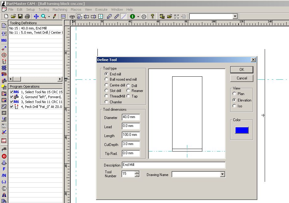
Under tool dimensions you have the diameter of the tool, the lead only applies to drills and is to take into concideration the pointy bit.
The length is nor critical as it's only the visual represtation of the tool, this figure isn't used in the code.
Cut depth is the critical one, this tells the tool how much to remover per cut, it may cut less as it equals the cuts out over the total depth but it should never cut more. In the example above it limits the cutter to 3mm depth.
Tip radius is what it says and is needed when calculating merged paths.
John S.
-
07-29-2009, 10:31 AM #35
Registered
- Join Date
- Nov 2005
- Posts
- 1468
When you click on the "Face Mill" option then click on it in the panel.It should bring up your face mill options. See the "Swathe" option down the right hand bottom- that's your tool overlap, usualy defaults to 70%- that means that after the first pass 70% of the tool will be cutting on the next pass- stick it to 50% for a half overlap on the tool or even 25% so that 75% of the tool overlaps. Fool about with the Swathe option and run the simulation till you get the amount of cuts you want.
Area Clear is the same- see the 4th Tab "Options"?- Swathe is up the top under that.
Pocket is the same (except it goes from 0- 1, not 0% - 100% so 0.7= 70%)
If you're pocketing you could go for large Z depths and a small overlap- you'd be side milling then so be sure to climb cut and use the uni- directional tab.
Or on face milling you could lie to it and tell it the diameter of the tool is half what it actualy is. Don't do this on pocketing or the pocket will end up bigger than you want.
Or on face milling you could lie again and tell it the limits of the face mill operation are (say) an inch over the edge of the part.
Lots of ways to do it.
I think that's what you meant?I love deadlines- I like the whooshing sound they make as they fly by.
-
08-20-2009, 06:42 AM #36
Registered
- Join Date
- Jul 2008
- Posts
- 922
You guys are awsome! thanks so much your great advice helped and i sorted that problem
One more problem lol.
click on the thumbnail for a bigger picture.

I want to create a contour of that entire outside shape, then have each of the slots/holes in the middle their own contour. However, i only know how to create contours of segments which would make the cam quite cumbersome. How do i select multiple segments at once (ie. you can see how i hovered over a "segment" which would be a contour in the picture, not the entire outer shape)?
second: is there a way to "pan" in the cad? i can't seem to figure it out
also third and final. I have been wanting to ask this for a while.
I want to make this type of thing
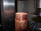
(click for bigger version)
with the tool on the right (slitting saw). I was reading in the manual i can create my own tooling (say the slitting saw) but would it be possible to create this sort of thing? the key is when its cutting the z cannot move, so would just "move to (x,y,z)" then goround a circle then move to (x,y,z)" be the only way i could do it?
does that make sense? lol sorry if it doesn't, im a bit tired.
Thanks so much gang
-
08-20-2009, 06:58 PM #37
Registered
- Join Date
- Dec 2003
- Posts
- 259
Stick the .dra file up and I'll talk you thru it.
Have to be next week now as I'm away at a show and internet access is patchy.
-
08-21-2009, 05:45 AM #38
Registered
- Join Date
- Jul 2008
- Posts
- 922
whenever is convinient for sir john s the great Originally Posted by John S.
but how should i upload a .dra? i can't stick up a dxf because im on my mums laptop - i.e. not on a licensed copy of dolphin (thats at home).
Cheers
-
08-24-2009, 09:20 AM #39
Registered
- Join Date
- Dec 2007
- Posts
- 496
Cant you zip it and send to an email of yours to upload?
-
08-30-2009, 12:10 AM #40
Registered
- Join Date
- Jul 2008
- Posts
- 922
Touche, ill give that a shot. but i decided i want to get the basics down before i try making more advanced parts.
Today was the first day that i was able to cook up some g-code via dolphin and run it on some plastic! however i got 2 weird issues.
It was facemilling, and mid face milling the z axis hopped up from -.125" to 1.95" (?) when in the code there was NO z axis instructions. However when i tried again later, it surfaced the part perfectly.
Then, when i want it to cut a circle around the part im making it won't and i just get a "zero radius arcline 38" in the status bar. Not sure what this is?
I have a video to show what i mean but its taking forever to upload.
Here is the first 50 lines of the code
N5G00G20G17G90G40G49G80
N6G49
N7T1M06 ( End Mill )
N8G00G43Z3.0H1
N9S1000M03
N10G94
N11S1000
N12X1.2625Y-1.0375
N13Z0.1181
N14G01Z-0.125F25.0
N15X-1.2625Y-1.0375
N16X-1.2625Y-0.8646
N17X1.2625Y-0.8646
N18X1.2625Y-0.6917
N19X-1.2625Y-0.6917
N20X-1.2625Y-0.5188
N21X1.2625Y-0.5188
N22X1.2625Y-0.3458
N23X-1.2625Y-0.3458
N24X-1.2625Y-0.1729
N25X1.2625Y-0.1729
N26X1.2625Y0.0
N27X-1.2625Y0.0
N28X-1.2625Y0.1729
N29X1.2625Y0.1729
N30X1.2625Y0.3458
N31X-1.2625Y0.3458
N32X-1.2625Y0.5188
N33X1.2625Y0.5188
N34X1.2625Y0.6917
N35X-1.2625Y0.6917
N36X-1.2625Y0.8646
N37X1.2625Y0.8646
N38X1.2625Y1.0375
N39X-1.2625Y1.0375
N40G00Z0.1181
N41X1.1875Y0.0
N42G01Z-0.125
N43G02X0.0Y-1.1875I0.0J0.0
N44X-1.1875Y0.0I0.0J0.0
N45X0.0Y1.1875I0.0J0.0
N46X1.1875Y0.0I0.0J0.0
N47G01Z-0.25
N48G02X0.0Y-1.1875I0.0J0.0
N49X-1.1875Y0.0I0.0J0.0
N50X0.0Y1.1875I0.0J0.0
Thanks so much in advance!

 Reply With Quote

Similar Threads
-
TL-2 Simple Questions
By Tazzer in forum Haas LathesReplies: 17Last Post: 03-21-2009, 03:04 PM -
A Couple Simple Mini Lathe Conversion Questions
By Cartierusm in forum Benchtop MachinesReplies: 14Last Post: 02-27-2009, 12:46 PM -
A couple more simple questions for a CNC builder
By Danno in forum CNC (Mill / Lathe) Control Software (NC)Replies: 3Last Post: 12-11-2008, 06:27 PM -
Simple Questions
By pzzamakr1980 in forum MastercamReplies: 11Last Post: 03-12-2008, 02:54 PM -
Simple questions.
By Dr Honda in forum Gecko DrivesReplies: 2Last Post: 09-11-2007, 04:51 AM
