


I was looking on digikey and its $3.82 each CAD. I will have to see how much future charges to ship, thanks.
Thread: CPLD Tutorial
Results 241 to 260 of 306
-
12-24-2009, 03:09 PM #241
 Registered
- Join Date
- Nov 2006
- Posts
- 104
-
12-24-2009, 05:39 PM #242
Registered
- Join Date
- Dec 2008
- Posts
- 28
$7.50CAD all around Canada. For me, If I will place order before 3:00pm I will get parcel on next day before 3:00pm (FedEx delivery). Originally Posted by fahque99

Digikey is the most expensive online store in the Internet.
-
12-26-2009, 10:44 AM #243
Registered
- Join Date
- Apr 2007
- Posts
- 5
CPU Select???
I got the how to make the microstep table thank everybody.
I want to ask , if I want to make 1/256 microstep table ,and want to run the motor with 1500 rpm , what kind of cpu should I select or how much MIPS should be? ADC or DAC resolution ??? for 256 microstep its enough 10 bit
Also How we write look up table in verilog ? can anybody send an example
Happy New Year
Erkan
-
12-26-2009, 10:37 PM #244
Registered
- Join Date
- Dec 2008
- Posts
- 28
If you want to do this, please read this first. Originally Posted by ekocakaya
1/256 microstep is useless. If you want to run motor at 1500rpm 1/256 microstep I would redirect your question to Google: stepper motor control theory.
-
12-27-2009, 08:03 AM #245
Registered
- Join Date
- Apr 2007
- Posts
- 5
Thanks
Thank u for quick reply , I read it yes you are right , 1/256 for 1500 rpm useless. But I only want to learn its technique for cpu and dac selection?
In chinesee step drivers they have 1/256 step dip switches and current switches , how they change the current , I look up inside the driver there is Xilinx CPLD and also some IC like LM339 LM358 IR2104 IRF640 but some of chips labels is erased . They are very smart , What are these chips do you think????
-
12-27-2009, 02:56 PM #246
Member
- Join Date
- Sep 2007
- Posts
- 22
Hello All...
On another thread, Mariss has offered to give us gerbers for his cpld development breadboard. I am interested.
Would anyone else like to join me for volume buy of pcb's? Does anyone buy boards often?
Great information here and talented people also.
Thank you Mariss and all the others that contribute.
Roger
-
12-30-2009, 10:19 AM #247
Registered
- Join Date
- Apr 2008
- Posts
- 3
Hallo
I need your help, i like to make my own drives but i can't find any shemas for doing that. The problem is that i am new in this business. I'v got unipolar 4A stepmotors. I'v posted the same question in CNC DRIVES but they redirect me here.
Thanks
-
12-30-2009, 10:30 PM #248
Registered
- Join Date
- Dec 2008
- Posts
- 28
Schematic is in the CPLD Tutorial. Tutorial is in this thread. Originally Posted by blazevski
-
12-31-2009, 11:42 PM #249
Gold Member
- Join Date
- Jan 2005
- Posts
- 1695
I would like to thank Mariss for the tutorial. I originally implemented a fixed time off design in VHDL. Unfortunately, I had to take a 1 year hiatus from this hobby. Now I could not find the code and also I realized that my newly acquired knowledge of VHDL has faded due to the lack of use. The tutorial will be extremely helpful. I'll learn Verilog this time.
-
01-01-2010, 04:35 AM #250
Gold Member
- Join Date
- Mar 2003
- Posts
- 2839
Happy New Year. Here are the promised breadboard gerber files.
Mariss
-
02-26-2010, 06:56 PM #251
Registered
- Join Date
- Dec 2008
- Posts
- 1
Thank you for the tutorial
Hello,
First, let me express my warmest thanks for making this tutorial.
For some time now I have been planning a CNC controlled mill project and decided to start with the basics, ie. getting some step motors to run. I had a microcontroller based design already running PWMs but decided to drop that in favor of some mixed signal circuitry. I already had my own logic/analog based design on the paper until I found this thread while doing information search on motor controllers. The given verilog example code saved me few weeks of my time.
I know I could have just bought 3 or 4 drives for the cost of tools and components in small quantities for my drive project but where would the fun be then? For an electronics engineer the answer is obvious. Also, knowing that something can be done makes whatever you are doing half done.
Well, to the point. This design as such is useless except for tutorial use but is rather easy to modify for proper 10 microstep operation. However, I am not after for a drive with limited functionality. To my understanding some nice features to add would be interleaving the PWM cycles, stabilisation circuitry and making microstepping sin/cos references to change in order to make the drive full step at higher velocities.
If anyone is interested in stabilisation circuitry there is a couple of patents that provide plenty of information. These have US numbers 4675590 and 4683409. These two should provide enough info to any dedicated person to realise a stabilised step motor drive - there is no need to follow the patents exactly but use them as pointers to right direction. Actual implementation can be done in several different ways. I think these two are the best examples on resonance compensation I found from a rather comprehensive research on stepper drives.
It is quite clear that for stabilisation a frequency to voltage converter and amplified/filtered feedback from current sensing resistors are needed. The delay element is easy to add into the example drive circuit. Latter of these patents has figure 5 which gives one example of a F2V, there element 21 (20 and 21 can be combined to an integrator) being the voltage output. Actual implementation of this can found in step pulse checker circuit I saw somewhere in this site too.
As for gradually changing the references to full step, I found this to be little more problematic at first. If I were to disclose how that can be done might upset someone so I will leave it for now except for a little teaser: The digital part should be as simple as adding one input to an existing gate in the example circuit.
However, I do have a question regarding those using commercial drives with changing reference waveforms: If I were to drive a motor forward with say 10 million steps and then the same amount backwards (with high enough max velocity, identical or different velocity profiles both ways) will the motor rotor return to exactly the same position it started from? In other words, does the reference alteration induce any positional errors?
Once again, thanks a lot for taking time to make this tutorial.
My "full featured" step motor drive is now bits and bytes in schematic/layout software but I will let you know how it works once I get it done.
-
03-23-2010, 08:54 PM #252
Registered
- Join Date
- Dec 2008
- Posts
- 28
Mariss, could you give more details about DUMP output?
G24 goes true for 3.2us every 51.2us. F12 S input goes true when STBY is low, for 400us after each STEP pulse.
As a result, after each STEP pulse DUMP output stays in "0" state for 400us and then starts to switch between Z and 0 for 3.2us every 51.2us
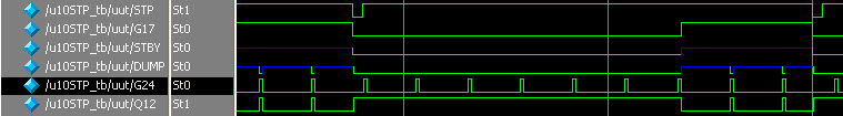
DF F12 (.C(CLK), .D(G24), .R(0), .CE(1), .S(~STBY), .Q(Q12));
assign DUMP = Q12 ? 1'b0 : 1'bz;//1'bz : 1'b0
assign G24 = QB[7] & QB[6] & QB[5] & QB[4];
Is it correct?
Thanks.
-
03-28-2010, 04:48 AM #253
Gold Member

- Join Date
- Jun 2003
- Posts
- 3312
see post 189 about dump, and 183 for code corrections. Originally Posted by boldive
Phil, Still too many interests, too many projects, and not enough time!!!!!!!!
Vist my websites - http://pminmo.com & http://millpcbs.com
-
03-29-2010, 03:47 PM #254
Registered
- Join Date
- Dec 2008
- Posts
- 28
Q12 operates the output enable on the output driver going to DUMP. This causes DUMP to go low for 3.2uS and be an open circuit the rest of the time.
Or
DUMP generates slope compensation ramps (0V to 2.5V) to stabilize the motor winding current feedback loops. Output shorts to ground for 3.2uS to dump the accumulated charge on ramp capacitor.
Is there any relation between DUMP and Blanking Time?
So, my question. Is it correct that DUMP goes low for the fist 400us of PWM cycle?
-
03-29-2010, 05:11 PM #255
Gold Member
- Join Date
- Jun 2003
- Posts
- 3312
I've kind of forgotten the details, but Dump doesn't become active till stby goes true.
http://www.cnczone.com/forums/showpo...&postcount=189
As I recall when stby goes true, Dump shorts the cap starting a new slope compenation ramp cycle based on the timing decode of G24.Phil, Still too many interests, too many projects, and not enough time!!!!!!!!
Vist my websites - http://pminmo.com & http://millpcbs.com
-
03-29-2010, 06:56 PM #256
Registered
- Join Date
- Dec 2008
- Posts
- 28
STBY goes true when no STEP Pulses. Motor stops. If it is not true, what is the reason to discharge STBY capacitor for 400us after every STEP pulse? Originally Posted by pminmo
One dump is for Phase A and B for slope compenation when STBY is High (motor is not running.
It looks like something is missing in tutorial or some steps have mistaken explanations. I understand Mariss. He can't give all details about G203V. And I want to say thank you for the start point which he gave us in tutorial.
-
03-29-2010, 07:26 PM #257
Gold Member
- Join Date
- Jun 2003
- Posts
- 3312
That is correct. Originally Posted by boldive
That is correct also, so what is it that your not understanding? Originally Posted by boldive
Phil, Still too many interests, too many projects, and not enough time!!!!!!!!
Vist my websites - http://pminmo.com & http://millpcbs.com
-
03-29-2010, 08:01 PM #258
Registered
- Join Date
- Dec 2008
- Posts
- 28
Phase A and B have 90° phase offset. It has to be one DUMP output per phase. Originally Posted by pminmo
Why DUMP goes low for the fist 400us of PWM cycle? What it does?
-
03-29-2010, 09:16 PM #259
Gold Member
- Join Date
- Jun 2003
- Posts
- 3312
Mariss hasn't answered this thread for awhile so I'll explain my understanding. (it's been sometime since I really looked at the tutorial and I could be wrong...) Originally Posted by boldive
Looking at the schematic Mariss provided in the tutorial, dump will generate a fairly linear ramp that will slightly alter the trip threshold of each phase when the motor is stopped. While true, there is a 90 degree phase offset in motor coil currents, the phase current is refelected in the polarity of the H bridge switch and the percentage of current in each phase as determined by the pwm dac.
Dump comes into play when the motor is stopped to diminish the motor hiss that annoys people because of the spurious frequency component.
I believe if you go back further in the thread, Mariss gave a brief explaination of slope compensation for which dump is used.Phil, Still too many interests, too many projects, and not enough time!!!!!!!!
Vist my websites - http://pminmo.com & http://millpcbs.com
-
04-01-2010, 03:21 AM #260
Registered
- Join Date
- Jan 2008
- Posts
- 15
hi all,
when the comparator goes "0" (current excess the required level) the output pins does reverse the polarity in the H bridge for the rest of the 20khz pulse, and later return to the polarity required or before to this RES pin reset the output forcing all to low and later start the new cicle?
i dont understand in the tutorial how it works because in some part of the tutorial is said RES pin is connected to capacitor + resistor to do a 1 second delay, same as stand by pin.
And I dont see RES pin in the schematic and in other part RES was said as synchronous signal for all when step pin input is received.
I think if you reverse polarity in a low step near to zero current (the first step) it reverse the polarity too much and don't work fine, for example when lm339 low time is longer than lm339 high time into the same pulse.
51us (20khz) - 3.3us blanking time = 47,7us
if lm339 low time is longer than 23us it will have a problem i think.

 Reply With Quote
Similar Threads
-
CPLD breadboard
By Mariss Freimanis in forum CNC Machine Related ElectronicsReplies: 1Last Post: 12-22-2009, 08:24 PM -
Using a CPLD to replace a few CMOS gates
By acondit in forum CNC Machine Related ElectronicsReplies: 102Last Post: 07-08-2009, 02:07 AM -
CPLD sizing
By tony ennis in forum CNC Machine Related ElectronicsReplies: 55Last Post: 06-09-2009, 01:03 AM -
CPLD Tutorial.
By Al_The_Man in forum CNC Machine Related ElectronicsReplies: 0Last Post: 05-18-2009, 06:32 PM -
JTAG CPLD programmer
By kreutz in forum CNC Machine Related ElectronicsReplies: 5Last Post: 09-25-2007, 05:17 AM
